Vimar 01546 User manual

Instructions manual
KNX weather station art. 01546
Installation manual

Table of Contents

Table of Contents
GENERAL FEATURES AND FUNCTIONALITY from page 5
ETS PARAMETERS AND COMMUNICATION OBJECTS from page 6
COMMUNICATION OBJECTS GENERAL FEATURES AND FUNCTIONALITY

4
For all the details about the Well-contact Plus system, refer to the installer manual that can be downloaded from
the Software Product Software Well-contact Plus section on the website www.vimar.com.
5
VIMAR group
General features and functionality
GENERAL FEATURES AND FUNCTIONALITY
KNX weather station
Weather station, KNX standard, power supply 12-32 Vdc or
12-24 Vac. Can be integrated with the By-me home auto-
mation system.
General information
The device measures quantities such as temperature, wind
speed, rainfall, and brightness whose values can be used
for viewing on supervisors or, on exceeding a threshold, to
activate automation systems in the installation. The KNX
weather station 01546 can be integrated with the By-me home
automation system via a dedicated configuration using the
EasyTool Professional software.
Characteristics
• Auxiliary supply voltage AUX: 12-32 V , 12-24 V~ SELV
• AUX current draw: 100 mA max, ripple 10%
Current draw from the Bus: 10 mA
• Terminals:
- Auxiliary power supply AUX
- TP bus connector
• Configuration push-button
• Configuration LED
• Configuration LED: 254 max
• Possible associations: 255 max
• Communication objects: 109
• Rain sensor heating: approximately 1.2 W
• Temperature measurement range: -40°C to +80°C
• Definition (temperature): 0.1°C
• Accuracy (temperature):
- 1°C with -10°C - +85°C
- 1.5°C with -25°C - +150°C
• Wind measurement range: 0 - 70 m/s
• Definition (wind): <10% of the reading
• Accuracy (wind): 25% with 0 - 15 m/s with an angle of
incidence of 45° and mounting on a suitable support
• Brightness measurement range: 0 - 150,000 Lux
• Definition (brightness):
- 1 Lux with 0-120 Lux
- 2 Lux with 121-1,046 Lux
- 63 Lux with 1,047-52,363 Lux
- 423 Lux with 52,364-150,000 Lux
• Accuracy (brightness): 35%
• Operating temperature: -30°C - +50°C (outdoor use)
• Protection class: IP44
• Dimensions: 96x77x118 mm (W x H x D)
• Weight: approximately 170 g
Operation
• Brightness measurement: the current brightness is measured
by the specific sensor.
• Wind measurement: the strength of the wind is measured
electronically and is quiet and reliable even in the event of hail,
snow and sub-zero temperatures.
The weather station is also able to detect whirlwinds and
updraughts.
• Precipitation measurement: the weather station is equipped
with a sensor with a heated surface so that only the raindrops
and snowflakes (and therefore not fog or dew) are measured
as precipitation. Once it has stopped raining or snowing, the
sensor dries quickly and the precipitation message is turned
off.
• Temperature measurement: the weather station measures
the value of the current ambient temperature.
• Control outputs for all values: the limit values can be set
via the respective parameters or via the ETS communication
objects.
• 8 AND logic gates and 8 OR logic gates each one with
4 inputs: the control operations themselves as well as the
8 logic inputs (in the form of communication objects) can be
used as inputs for the AND and OR logic gates; the output of
each gate can be configured as 1 bit or as 2 x 8 bits.
IMPORTANT: Press the configuration button to assign
the physical address to the device.
Behaviour after switching on the Bus
Switching on the Bus: the state will be set based on the setting
of the parameters and the corresponding telegrams sent over
the Bus.
Behaviour after reset
As for Bus on.
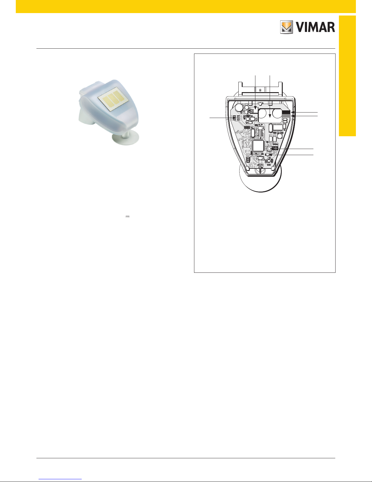
FRONT VIEW.
01546
1
24
3
5
6
+
-
1. Fast spring terminal for auxiliary power supply AUX; terminal assignment
is independent of polarity (+/- or -/+). Use a solid cable of cross-
section up to 1.5 mm2or a stranded cable.
2. Connector for connecting the cable of the precipitation sensor located
under the front cover of the weather station.
3. Space for feeding through the power supply cable and the Bus cable.
4. KNX TP Bus connector (-, +). We recommend using the KNX cable art.
01890 using a corrugated pipe for the outside or to protect the cable
from UV radiation.
5. Configuration button.
6. Configuration LED.

6
KNX weather station
No. ETS name Function Description Type Flag 1 Priority
C R W T U I
0 Night control output Output Sends the command over the BUS when the "Night"
condition occurs (1 = Night | 0 = Day). 1 bit C R - T - - Low
1 Rain control output Output Sends the command over the BUS when the "Rain"
condition occurs (1 = Rain | 0 = No Rain). 1 bit C R - T - - Low
2 Logic input 1 Input Input that can be enabled to be used for performing the
logic functions made available by the weather station. 1 bit C R W - - - Low
3 Logic input 2 Input Input that can be enabled to be used for performing the
logic functions made available by the weather station. 1 bit C R W - - - Low
4 Logic input 3 Input Input that can be enabled to be used for performing the
logic functions made available by the weather station. 1 bit C R W - - - Low
5 Logic input 4 Input Input that can be enabled to be used for performing the
logic functions made available by the weather station. 1 bit C R W - - - Low
6 Logic input 5 Input Input that can be enabled to be used for performing the
logic functions made available by the weather station. 1 bit C R W - - - Low
7 Logic input 6 Input Input that can be enabled to be used for performing the
logic functions made available by the weather station. 1 bit C R W - - - Low
8 Logic input 7 Input Input that can be enabled to be used for performing the
logic functions made available by the weather station. 1 bit C R W - - - Low
9 Logic input 8 Input Input that can be enabled to be used for performing the
logic functions made available by the weather station. 1 bit C R W - - - Low
10 Temperature sensor
error Output Indicates malfunctioning of the weather station temper-
ature sensor (0 = OK | 1 = NOT OK). 1 bit C R - T - - Low
11 Wind sensor error Output Indicates malfunctioning of the wind sensor
(0 = OK | 1 = NOT OK). 1 bit C R - T - - Low
12 Measured value
temperature Output Lets you know the temperature measured by the
weather station in °C. 2 bytes C R - T - - Low
13 Min/max temperature
request Request
Requests the weather station to send the measured
minimum and maximum temperature values over the
Bus.
1 bit C R W - - - Low
14 Measured min. temper-
ature value Sends min. temperature Lets you know the minimum temperature measured by
the weather station in °C. 2 bytes C R - T - - Low
15 Measured max. tem-
perature value Sends max. temperature Lets you know the maximum temperature measured by
the weather station in °C. 2 bytes C R - T - - Low
16 Min/max temperature
reset Temperature reset Deletes the saved minimum and maximum temperature
values. 1 bit C R W - - - Low
17 Temperature 1 LV Default value Temperature 1 limit value: to set the setpoint of the limit
value 2 bytes C R - T - - Low
18 Temperature 1 LV Actual value Temperature 1 limit value: to read the actual limit value 2 bytes C R W - - - Low
19 Temperature 2 LV Default value Temperature 2 limit value: to set the setpoint of the limit
value 2 bytes C R - T - - Low
20 Temperature 2 LV Actual value Temperature 2 limit value: to read the actual limit value 2 bytes C R W - - - Low
List of existing communication objects and standard settings
Continues C= Communication; R= Read; W= Write; T= Transmission; U= Enable update
ETS parameters and communication objects

7
VIMAR group
COMMUNICATION OBJECTS
KNX weather station
No. ETS name Function Description Type Flag 1 Priority
C R W T U I
21 Temperature 3 LV Default value Temperature 3 limit value: to set the setpoint of the limit
value 2 bytes C R - T - - Low
22 Temperature 3 LV Actual value Temperature 3 limit value: to read the actual limit value 2 bytes C R W - - - Low
23 Temperature 4 LV Default value Temperature 4 limit value: to set the setpoint of the limit
value 2 bytes C R - T - - Low
24 Temperature 4 LV Actual value Temperature 4 limit value: to read the actual limit value 2 bytes C R W - - - Low
25 Control output Temp 1 LV Temperature 1 Limit Value control output. 1 bit C R - T - - Low
26 Control output Temp 2 LV Temperature 2 Limit Value control output. 1 bit C R - T - - Low
27 Control output Temp 3 LV Temperature 3 Limit Value control output. 1 bit C R - T - - Low
28 Control output Temp 4 LV Temperature 4 Limit Value control output. 1 bit C R - T - - Low
29 Measured value
wind speed Output Lets you know the wind speed measured by the weath-
er station in m/s. 2 bytes C R - T - - Low
30 Request for max. wind
strength Request Requests the weather station to send the measured
maximum wind speed value over the Bus. 1 bit C R W - - - Low
31 Max. measured wind
strength value
Sends the maximum wind
strength
Lets you know the maximum wind speed measured by
the weather station in m/s. 2 bytes C R - T - - Low
32 Reset max. wind
strength Wind strength reset Deletes the saved maximum wind strength value. 1 bit C R W - - - Low
33 Wind speed 1 LV Default value Wind speed 1 limit value: to set the setpoint of the limit
value 2 bytes C R W T U - Low
34 Wind speed 1 LV Actual value Wind speed 1 limit value: to read the actual limit value 2 bytes C R W - - - Low
35 Wind speed 2 LV Default value Wind speed 2 limit value: to set the setpoint of the limit
value 2 bytes C R W T U - Low
36 Wind speed 2 LV Actual value Wind speed 2 limit value: to read the actual limit value 2 bytes C R W - - - Low
37 Wind speed 3 LV Default value Wind speed 3 limit value: to set the setpoint of the limit
value 2 bytes C R W T U - Low
38 Wind speed 3 LV Actual value Wind speed 3 limit value: to read the actual limit value 2 bytes C R W - - - Low
39 Control output Wind 1 LV Wind Speed 1 Limit Value control output. 1 bit C R - T - - Low
40 Control output Wind 2 LV Wind Speed 2 Limit Value control output. 1 bit C R - T - - Low
41 Control output Wind 3 LV Wind Speed 3 Limit Value control output. 1 bit C R - T - - Low
42 Measured value
brightness Output Lets you know the brightness measured by the weather
station in lux. 2 bytes C R - T - - Low
43 Limit value
brightness 1 Default value Brightness 1 limit value: to set the setpoint of the limit
value 2 bytes C R W T U - Low
44 Limit value
brightness 1 Actual value Brightness 1 limit value: to read the actual limit value 2 bytes C R W - - - Low
Continued
Continues C= Communication; R= Read; W= Write; T= Transmission; U= Enable update
ETS parameters and communication objects

8
No. ETS name Function Description Type Flag 1 Priority
C R W T U I
45 Limit value
brightness 2 Default value Brightness 2 limit value: to set the setpoint of the limit
value 2 bytes C R W T U - Low
46 Limit value
brightness 2 Actual value Brightness 2 limit value: to read the actual limit value 2 bytes C R W - - - Low
47 Limit value
brightness 3 Default value Brightness 3 limit value: to set the setpoint of the limit
value 2 bytes C R W T U - Low
48 Limit value
brightness 3 Actual value Brightness 3 limit value: to read the actual limit value 2 bytes C R W - - - Low
49 Control output Brightness 1 LV Brightness 1 Limit Value control output. 1 bit C R - T - - Low
50 Control output Brightness 2 LV Brightness 2 Limit Value control output. 1 bit C R - T - - Low
51 Control output Brightness 3 LV Brightness 3 Limit Value control output. 1 bit C R - T - - Low
52 Limit value
twilight 1 Default value Twilight function 1 limit value: to set the setpoint of the
limit value 2 bytes C R W T U - Low
53 Limit value
twilight 1 Actual value Twilight function 1 limit value: to read the actual limit
value 2 bytes C R W - - - Low
54 Limit value
twilight 2 Default value Twilight function 2 limit value: to set the setpoint of the
limit value 2 bytes C R W T U - Low
55 Limit value
twilight 2 Actual value Twilight function 2 limit value: to read the actual limit
value 2 bytes C R W - - - Low
56 Limit value
twilight 3 Default value Twilight function 3 limit value: to set the setpoint of the
limit value 2 bytes C R W T U - Low
57 Limit value
twilight 3 Actual value Twilight function 3 limit value: to read the actual limit
value 2 bytes C R W - - - Low
58 Twilight 1 LV control
output Output Twilight 1 Limit Value control output. 1 bit C R - T - - Low
59 Twilight 2 LV control
output Output Twilight 2 Limit Value control output. 1 bit C R - T - - Low
60 Twilight 3 LV control
output Output Twilight 3 Limit Value control output. 1 bit C R - T - - Low
61 Logic AND 1 Control output Logic output AND 1 at 1 bit. 1 bit C R - T - - Low
62 Logic AND 1 Output A at 8 bits Output A at 8 bits of the logic output AND 1. 1 bytes C R - T - - Low
63 Logic AND 1 Output B at 8 bits Output B at 8 bits of the logic output AND 1. 1 bytes C R - T - - Low
64 Logic AND 2 Control output Logic output AND 2 at 1 bit. 1 bit C R - T - - Low
65 Logic AND 2 Output A at 8 bits Output A at 8 bits of the logic output AND 2. 1 bytes C R - T - - Low
66 Logic AND 2 Output B at 8 bits Output B at 8 bits of the logic output AND 2. 1 bytes C R - T - - Low
67 Logic AND 3 Control output Logic output AND 3 at 1 bit. 1 bit C R - T - - Low
68 Logic AND 3 Output A at 8 bits Output A at 8 bits of the logic output AND 3. 1 bytes C R - T - - Low
69 Logic AND 3 Output B at 8 bits Output B at 8 bits of the logic output AND 3. 1 bytes C R - T - - Low
70 Logic AND 4 Control output Logic output AND 4 at 1 bit. 1 bit C R - T - - Low
71 Logic AND 4 Output A at 8 bits Output A at 8 bits of the logic output AND 4. 1 bytes C R - T - - Low
Continues C= Communication; R= Read; W= Write; T= Transmission; U= Enable update
Continued
ETS parameters and communication objects
KNX weather station

9
VIMAR group
Continued
Continues C= Communication; R= Read; W= Write; T= Transmission; U= Enable update
No. ETS name Function Description Type Flag 1 Priority
C R W T U I
72 Logic AND 4 Output B at 8 bits Output B at 8 bits of the logic output AND 4. 1 bytes C R - T - - Low
73 Logic AND 5 Control output Logic output AND 5 at 1 bit. 1 bit C R - T - - Low
74 Logic AND 5 Output A at 8 bits Output A at 8 bits of the logic output AND 5. 1 bytes C R - T - - Low
75 Logic AND 5 Output B at 8 bits Output B at 8 bits of the logic output AND 5. 1 bytes C R - T - - Low
76 Logic AND 6 Control output Logic output AND 6 at 1 bit. 1 bit C R - T - - Low
77 Logic AND 6 Output A at 8 bits Output A at 8 bits of the logic output AND 6. 1 bytes C R - T - - Low
78 Logic AND 6 Output B at 8 bits Output B at 8 bits of the logic output AND 6. 1 bytes C R - T - - Low
79 Logic AND 7 Control output Logic output AND 7 at 1 bit. 1 bit C R - T - - Low
80 Logic AND 7 Output A at 8 bits Output A at 8 bits of the logic output AND 7. 1 bytes C R - T - - Low
81 Logic AND 7 Output B at 8 bits Output B at 8 bits of the logic output AND 7. 1 bytes C R - T - - Low
82 Logic AND 8 Control output Logic output AND 8 at 1 bit. 1 bit C R - T - - Low
83 Logic AND 8 Output A at 8 bits Output A at 8 bits of the logic output AND 8. 1 bytes C R - T - - Low
84 Logic AND 8 Output B at 8 bits Output B at 8 bits of the logic output AND 8. 1 bytes C R - T - - Low
85 Logic OR 1 Control output Logic output OR 1 at 1 bit. 1 bit C R - T - - Low
86 Logic OR 1 Output A at 8 bits Output A at 8 bits of the logic output OR 1. 1 bytes C R - T - - Low
87 Logic OR 1 Output B at 8 bits Output B at 8 bits of the logic output OR 1. 1 bytes C R - T - - Low
88 Logic OR 2 Control output Logic output OR 2 at 1 bit. 1 bit C R - T - - Low
89 Logic OR 2 Output A at 8 bits Output A at 8 bits of the logic output OR 2. 1 bytes C R - T - - Low
90 Logic OR 2 Output B at 8 bits Output B at 8 bits of the logic output OR 2. 1 bytes C R - T - - Low
91 Logic OR 3 Control output Logic output OR 3 at 1 bit. 1 bit C R - T - - Low
92 Logic OR 3 Output A at 8 bits Output A at 8 bits of the logic output OR 3. 1 bytes C R - T - - Low
93 Logic OR 3 Output B at 8 bits Output B at 8 bits of the logic output OR 3. 1 bytes C R - T - - Low
94 Logic OR 4 Control output Logic output OR 4 at 1 bit. 1 bit C R - T - - Low
95 Logic OR 4 Output A at 8 bits Output A at 8 bits of the logic output OR 4. 1 bytes C R - T - - Low
96 Logic OR 4 Output B at 8 bits Output B at 8 bits of the logic output OR 4. 1 bytes C R - T - - Low
97 Logic OR 5 Control output Logic output OR 5 at 1 bit. 1 bit C R - T - - Low
98 Logic OR 5 Output A at 8 bits Output A at 8 bits of the logic output OR 5. 1 bytes C R - T - - Low
99 Logic OR 5 Output B at 8 bits Output B at 8 bits of the logic output OR 5. 1 bytes C R - T - - Low
COMMUNICATION OBJECTS
ETS parameters and communication objects
KNX weather station

10
No. ETS name Function Description Type Flag 1 Priority
C R W T U I
100 Logic OR 6 Control output Logic output OR 6 at 1 bit. 1 bit C R - T - - Low
101 Logic OR 6 Output A at 8 bits Output A at 8 bits of the logic output OR 6. 1 bytes C R - T - - Low
102 Logic OR 6 Output B at 8 bits Output B at 8 bits of the logic output OR 6. 1 bytes C R - T - - Low
103 Logic OR 7 Control output Logic output OR 7 at 1 bit. 1 bit C R - T - - Low
104 Logic OR 7 Output A at 8 bits Output A at 8 bits of the logic output OR 7. 1 bytes C R - T - - Low
105 Logic OR 7 Output B at 8 bits Output B at 8 bits of the logic output OR 7. 1 bytes C R - T - - Low
106 Logic OR 8 Control output Logic output OR 8 at 1 bit. 1 bit C R - T - - Low
107 Logic OR 8 Output A at 8 bits Output A at 8 bits of the logic output OR 8. 1 bytes C R - T - - Low
108 Logic OR 8 Output B at 8 bits Output B at 8 bits of the logic output OR 8. 1 bytes C R - T - - Low
Continued
ETS parameters and communication objects
C= Communication; R= Read; W= Write; T= Transmission; U= Enable update
KNX weather station
Number of communication objects Max. number of group addresses Max. number of associations
109 254 255
11
VIMAR group
ETS parameters and communication objects
COMMUNICATION OBJECTS
KNX weather station
Reference ETS parameters
Behaviour in the event of a power failure and when
power is restored.
Behaviour if there is no Bus voltage or auxiliary voltage:
The device transmits no data.
Behaviour if there is no Bus voltage or auxiliary voltage and
subsequent programming or restarting:
The device sends all the measured values, control outputs and
the status of the logic gates according to the behaviour set by
the parameters in the "General Settings". When powering up,
information will be sent with a settable delay.
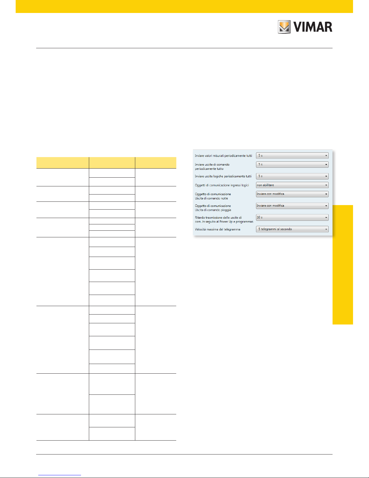
General settings
General settings
ETS text Available values Comment
[Default value]
Send measured values
periodically all
5 s ... 2 h
[5 s]
Send control outputs peri-
odically all
5 s ... 2 h
[5 s]
Send logic outputs
periodically all
5 s ... 2 h
[5 s]
Logic input communication
objects
do not enable
enable
[do not enable]
Night control output com-
munication object
Do not send
Send with change
Send reversed with
change
Send with change and
cyclically
Send reversed with
change and cyclically
[Send with change]
Rain control output com-
munication object
Do not send
Send with change
Send reversed with
change
Send with change and
cyclically
Send reversed with
change and cyclically
[Send with change]
Control output transmission
delay after Power up and
programm.
5 s ... 2 h When powering up
and after program-
ming, the weather
station waits for the
set time delay before
transmitting the
control outputs.
[10 s]
Maximum speed of the
telegram
1... 20 telegrams
per second
[5 telegrams per
second]
12
ETS parameters and communication objects
KNX weather station
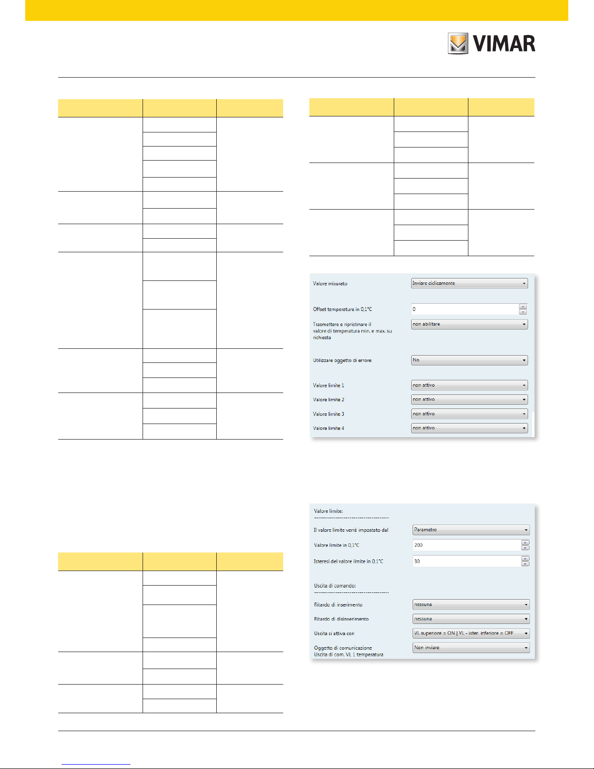
Temperature
Temperature
ETS text Available values Comment
[Default value]
Measured value
Do not send
Send cyclically
Send with change
Send with change or
cyclically
[Send cyclically]
Starting from a temperature
change of
0.5 °C ... 5 °C It is displayed when
selecting "Send
with change" for the
measured value
[0.5 °C]
Temperature offset 0.1°C
-50...50
[0]
Transmit and reset the min.
and max temperature value
on request
do not enable Enables/disables
the communication
objects 13-14-15
and 16.
13-Min/max temper-
ature request.
14-Measured min.
temperature value.
15-Measured max.
temperature value.
16-Min/max temper-
ature reset.
enable
[do not enable]
Use error object
No Enables/disables
communication
object:
10- Temperature
sensor error
Yes
[No]
Limit value 1
off
on
[off]
Limit value 1,2,3,4
When the above parameter Limit Value is selected as on it is
necessary to set its characteristics and those of the Control
output too.
Limit value on
ETS text Available values Comment
[Default value]
The limit value will be
set by the
Parameter
Communication
object
Communication
object saving the last
value
[Parameter]
Limit value in 0.1°C
-300 ...800
[200]
Hysteresis of the limit value
in 0.1°C
0..100 See par. Hysteresis
on page 20
[30]
ETS text Available values Comment
[Default value]
Limit value 2
off
on
[off]
Limit value 3
off
on
[off]
Limit value 4
off
on
[off]
Continues
Continued
Continues

13
VIMAR group
ETS parameters and communication objects
COMMUNICATION OBJECTS
KNX weather station
ETS text Available values Comment
[Default value]
On delay none, 1s, 1min...2h
[none]
Off delay
none, 1s, 1min...2h
[none]
Output activates with
LV upper = ON |
LV - lower hyst. = OFF
LV lower = ON |
LV + lower hyst. = OFF
[LV upper = ON |
LV - lower hyst. = OFF]
Control output communica-
tion object LV 1
temperature
Do not send
Send with change
Send reversed with
change
Send with change and
cyclically
Send reversed with
change and cyclically
[Do not send]
Continued
Limit value set by "Comm. object saving the last value"
Note: If the threshold value is set by a communication object,
the threshold value must be specified during configuration
because this value remains valid until the 1st object is sent with
the new threshold value. In the case of weather stations that
have already been put into service, the last threshold value sent
by the communication object is used. If a threshold is set once
using the parameter or a communication object, the last set
threshold value remains until a new threshold value is transmitted
by a communication object. The last threshold values set by the
communication objects are saved in EEPROM memory, so as to
preserve the values during a power failure that are then available
when power is restored.
Wind
ETS text Available values Comment
[Default value]
Measured value
Do not send
Send cyclically
Send with change
Send with change or
cyclically
[Send cyclically]
Starting from a change in
wind strength of:
1m/s...4m/s It is displayed when
selecting "Send with
change" and "Send
with change and
cyclically"
[1m/s]
Transmit and reset the max
wind strength value on
request
do not enable Enables/disables the
communication ob-
jects 30-31 and 32.
30- Request for max.
wind strength
31-Max. measured
wind strength value.
32-Reset max. wind
strength.
enable
[do not enable]
Use error object
No Enables/disables
communication
object:
11- Wind sensor
error.
Yes
[No]
Limit value 1
off
on
[off]Wind
ETS text Available values Comment
[Default value]
Limit value 2
off
on
[off]
Limit value 2
off
on
[off]
Continues
Continued
14
ETS parameters and communication objects
KNX weather station
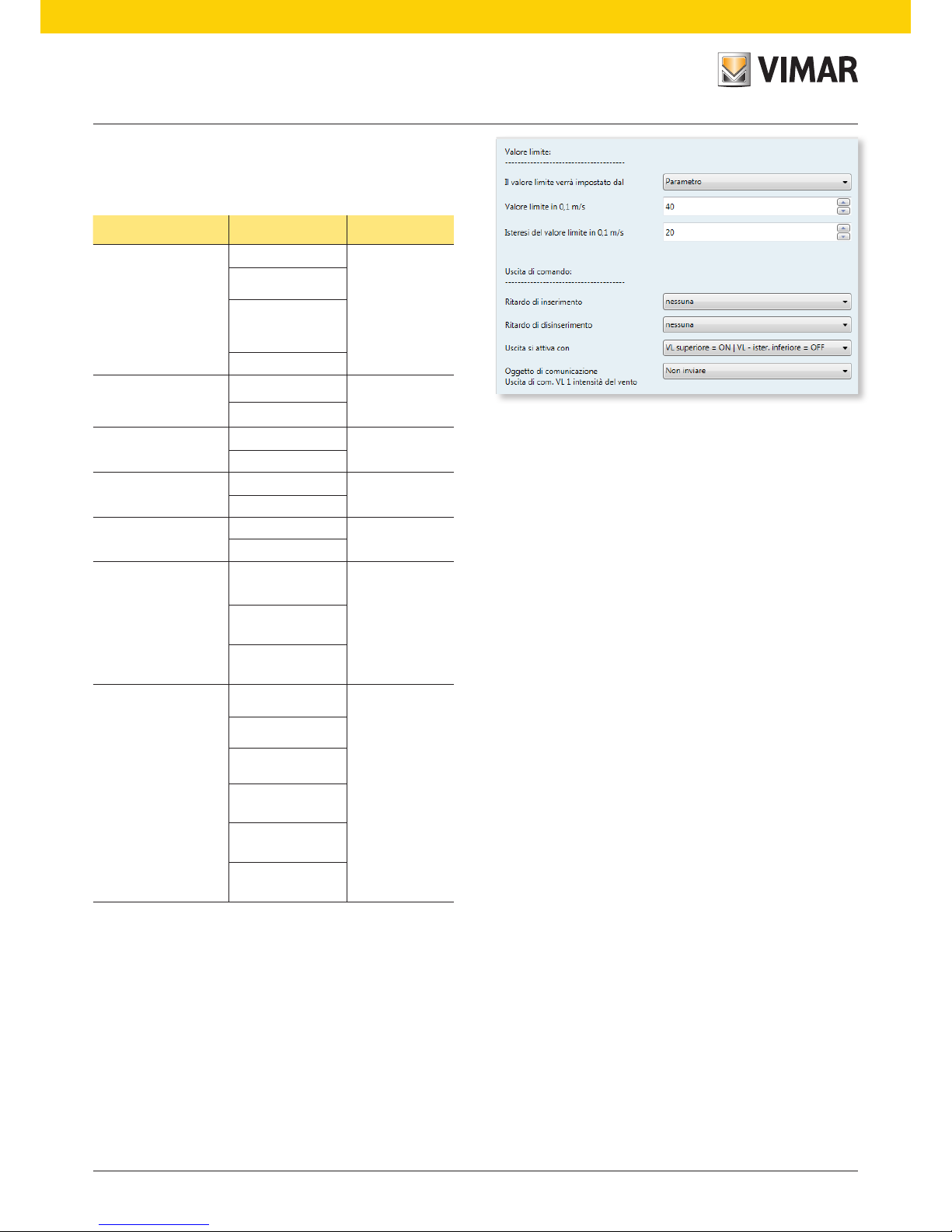
Limit value 1,2,3
When the above parameter Limit Value is selected as on it is
necessary to set its characteristics and those of the Control
output too.
ETS text Available values Comment
[Default value]
The limit value will be
set by the
Parameter
Communication
object
Communication
object saving the last
value
[Parameter]
Limit value in 0.1 m/s
0 ...350
[40]
Hysteresis of the limit value
in 0.1 m/s
0..250 See par. Hysteresis
on page 20
[20]
On delay
none, 1s, 1min...2h
[none]
Off delay
none, 1s, 1min...2h
[none]
Output activates with
LV upper = ON |
LV - lower hyst. = OFF
LV lower = ON |
LV + lower hyst. = OFF
[LV upper = ON |
LV - lower hyst. = OFF]
Control output commu-
nication object LV 1 wind
strength
Do not send
Send with change
Send reversed with
change
Send with change and
cyclically
Send reversed with
change and cyclically
[Do not send]
Limit value on
Note: If the threshold value is set by a communication object,
the threshold value must be specified during configuration
because this value remains valid until the 1st object is sent with
the new threshold value.
In the case of weather stations that have already been put into
service, the last threshold value sent by the communication
object is used.
If a threshold is set once using the parameter or a communication
object, the last set threshold value remains until a new threshold
value is transmitted by a communication object.
The last threshold values set by the communication objects are
saved in EEPROM memory, so as to preserve the values during
a power failure that are then available when power is restored.

15
VIMAR group
ETS parameters and communication objects
COMMUNICATION OBJECTS
KNX weather station
Brightness
Brightness
ETS text Available values Comment
[Default value]
Measured value
Do not send
Send cyclically
Send with change
Send with change or
cyclically
[Send cyclically]
Starting from a change
in %
1 ... 50
It is displayed when
selecting "Send with
change" and "Send
with change and
cyclically" for the
measured value
[10]
Limit value 1
off
on
[off]
Limit value 2
off
on
[off]
Limit value 1,2,3
When the above parameter Limit Value is selected as on it is
necessary to set its characteristics and those of the Control
output too.
Limit value on
ETS text Available values Comment
[Default value]
The limit value will be
set by the
Parameter
Communication
object
Communication
object saving the last
value
[Parameter]
Limit value in klux 1 ...99
[5]
Hysteresis of the limit value
in klux
0..99 See par. Hysteresis
on page 20
[2]
On delay
none, 1s, 1min...2h
[none]
Off delay
none, 1s, 1min...2h
[none]
Output activates with
LV upper = ON |
LV - lower hyst. = OFF
LV lower = ON |
LV + lower hyst. = OFF
[LV upper = ON |
LV - lower hyst. = OFF]
Continues
ETS text Available values Comment
[Default value]
Limit value 3
off
on
[off]
Continues
Continued

16
ETS parameters and communication objects
KNX weather station
ETS text Available values Comment
[Default value]
Control output communica-
tion object LV 1 brightness
Do not send
Send with change
Send reversed with
change
Send with change and
cyclically
Send reversed with
change and cyclically
[Do not send]
Continued Note: If the threshold value is set by a communication object,
the threshold value must be specified during configuration
because this value remains valid until the 1st object is sent with
the new threshold value.
In the case of weather stations that have already been put into
service, the last threshold value sent by the communication
object is used.
If a threshold is set once using the parameter or a communication
object, the last set threshold value remains until a new threshold
value is transmitted by a communication object.
The last threshold values set by the communication objects are
saved in EEPROM memory, so as to preserve the values during
a power failure that are then available when power is restored.
Twilight
ETS text Available values Comment
[Default value]
Limit value 1
off
on
[off]
Limit value 2
off
on
[off]
Limit value 2
off
on
[off]
Twilight
Limit value 1,2,3
When the above parameter Limit Value is selected as on it is
necessary to set its characteristics and those of the Control
output too.
Limit value on
ETS text Available values Comment
[Default value]
The limit value will be
set by the
Parameter
Communication
object
Communication
object saving the last
value
[Parameter]
Limit value in lux 1 ...1000
[200]
Hysteresis of the limit value
in lux
0..1000 See par. Hysteresis
on page 20
[50]
On delay none, 1s, 1min...2h
[none]
Off delay none, 1s, 1min...2h
[none]
17
VIMAR group
COMMUNICATION OBJECTS
ETS parameters and communication objects
KNX weather station
ETS text Available values Comment
[Default value]
Output activates with
LV upper = ON |
LV - lower hyst. = OFF
LV lower = ON |
LV + lower hyst. = OFF
[LV upper = ON |
LV - lower hyst. = OFF]
Control output communica-
tion object LV 1 twilight
Do not send
Send with change
Send reversed with
change
Send with change and
cyclically
Send reversed with
change and cyclically
[Do not send]
Note: If the threshold value is set by a communication object,
the threshold value must be specified during configuration
because this value remains valid until the 1st object is sent
with the new threshold value.
In the case of weather stations that have already been put into
service, the last threshold value sent by the communication
object is used.
If a threshold is set once using the parameter or a
communication object, the last set threshold value remains
until a new threshold value is transmitted by a communication
object.
The last threshold values set by the communication objects
are saved in EEPROM memory, so as to preserve the values
during a power failure that are then available when power is
restored.
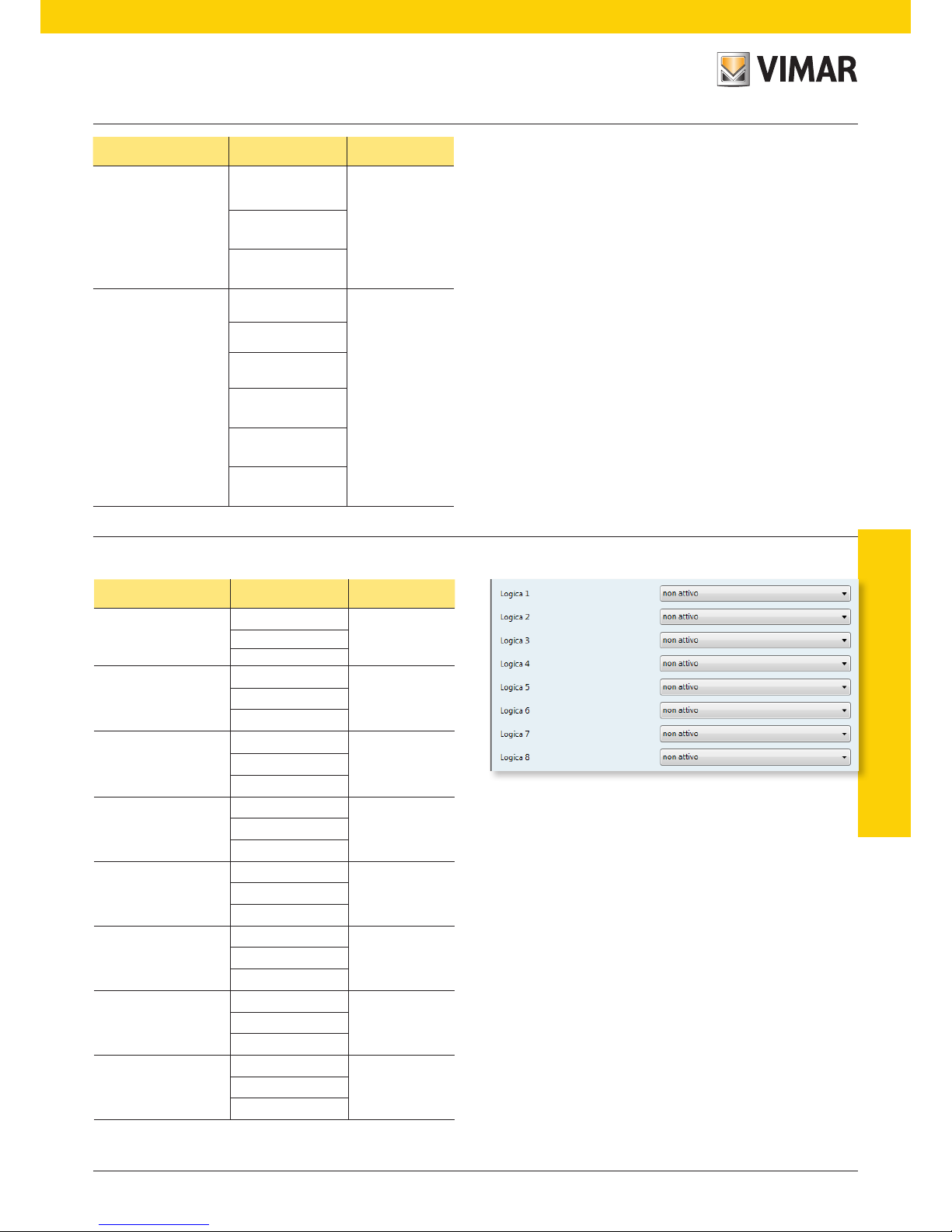
Logics
ETS text Available values Comment
[Default value]
Logic 1
off
on
[off]
Logic 2
off
on
[off]
Logic 3
off
on
[off]
Logic 4
off
on
[off]
Logic 5
off
on
[off]
Logic 6
off
on
[off]
Logic 7
off
on
[off]
Logic 8
off
on
[off]
Logics

18
ETS parameters and communication objects
KNX weather station
ETS text Available values Comment
[Default value]
1. Input
Do not use
Communication ob-
jects can be selected
as an input for the
logic function.
Night = 1
Night = 0
Limit value
twilight 1
Limit value
twilight 1 reversed
Limit value
twilight 2
Limit value
twilight 2 reversed
Limit value
twilight 3
Limit value
twilight 3 reversed
Limit value
brightness 1
Limit value
brightness 1 reversed
Limit value
brightness 2
Limit value
brightness 2 reversed
Limit value
brightness 3
Limit value
brightness 3 reversed
Logic input 1 communi-
cation object
Logic input 1 rev. com-
munication object
Logic input 2 communi-
cation object
Logic input 2 rev. com-
munication object
Logic input 3 communi-
cation object
Logic input 3 rev. com-
munication object
Logic input 4 communi-
cation object
Logic input 4 rev. com-
munication object
Logic input 5 communi-
cation object
Logic input 5 rev. com-
munication object
Logic input 6 communi-
cation object
Logic input 6 rev. com-
munication object
Logic input 7 communi-
cation object
Logic input 7 rev. com-
munication object
Logic input 8 communi-
cation object
Logic input 8 rev. com-
munication object
Logic AND
ETS text Available values Comment
[Default value]
1. Input
Rain Yes
Communication ob-
jects can be selected
as an input for the
logic function.
Rain No
Temperature error
Temperature error
reversed
Wind error
Reversed wind error
Temperature 1 LV
Temperature 1 LV
reversed
Temperature 2 LV
Temperature 2 LV
reversed
Temperature 3 LV
Temperature 3 LV
reversed
Temperature 4 LV
Temperature 4 LV
reversed
Wind 1 LV
Wind 1 LV reversed
Wind 2 LV
Wind 2 LV reversed
Wind 3 LV
Wind 3 LV reversed
[Do not use]
2. Input As 1. Input As 1. Input
3. Input As 1. Input As 1. Input
4. Input As 1. Input As 1. Input
Logic output transmits
no
one 1-bit object
two 8-bit objects
[no]
Continues
Continued
19
VIMAR group
COMMUNICATION OBJECTS
ETS parameters and communication objects
KNX weather station
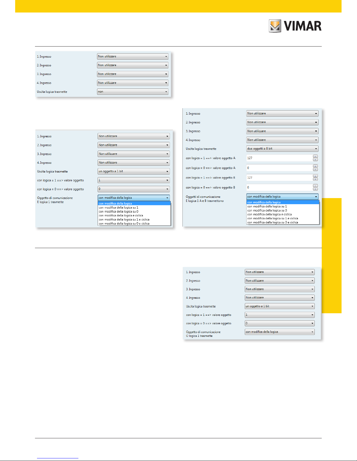
Logic AND
Logic AND with Logic output transmits "one 1-bit object" Logic AND with Logic output transmits "two 8-bit objects"
Logic OR
Logic OR
The parameters with which the OR logic gates are configured
are similar to those previously illustrated for the AND logic gates.
Therefore please refer to the information on the previous pages.

20
ETS parameters and communication objects
KNX weather station
Hysteresis of the limit value.
This section graphically illustrates the meaning of the Hysteresis parameter for the object with Limit Value 1,2,3 for Temperature, Wind,
Brightness and Twilight.
0
1
0
Limit Value
Hysteresis of
the
limit value
Limit Value control
output
Value of the quantity
(temperature, wind speed, brightness)
Table of contents
Other Vimar Weather Station manuals


