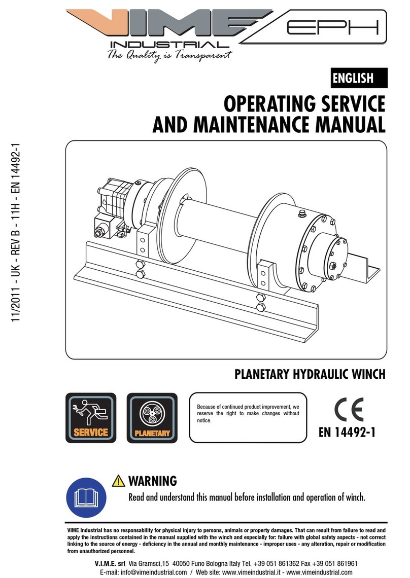
VIME INDUSTRIAL MH 9000 User manual

WORM GEAR HYDRAULIC WINCH
WARNING
Read and understand this manual before installation and operation of winch.
Keep this manual with the winch at all times.
V.I.M.E. srl
V
ia Gramsci,15 40050 Funo Bologna Italy Tel. +39 051 861362 Fax +39 051 861961
OPERATING SERVICE
AND MAINTENANCE MANUAL
ENGLISH
Because of continued product improvement, we
reserve the right to make changes without
notice.
VIME has no responsibility for physical injury to persons, animals or property damages. That can result from failure to read and apply the
instructions contained in the manual supplied with the winch and especially for: Failure with global safety aspects - Not correct linking to
the source of energy – Deficiency in the annual and monthly maintenance - Improper uses - Any alteration, repair or modification from
unauthorized personnel.
03/2013- UK - REV B - 07 - MH90
The Quality is Transparent
WORM GEAR
SERVICE

WARNING
Do not operate this winch until you have
fully read this manual.
Many accidents are due for non obser-
vance safety procedures. A good reason,
most of it can be avoided by knowing
causes and taking in advance the oppor-
tunity safety.
The Quality is Transparent
WARNING
Read and understand this manual before
installation and operation of winch.
Model MH 9000
Serial Number
Manufacture year
Max. rated line pull • MH 9000 9.000 kgs
Wire rope diameter • MH 9000 Dia. 16 mm
Max. pressure • MH 9000 160 bar
Weight (without cable) • MH 9000 112 kgs
1
WARRANTY
V.I.M.E. s.r.l. warrants to the original buyer , all parts and components except the wire rope , to be free from defects in materials and workman-
ship for a period of ( one ) 1 year for electrical and mechanical components. The obligation under this warranty , statutory or otherwise , is
limited to the replacement or repair at V.I.M.E. s.r.l. , or at a point designated by V.I.M.E. s.r.l. of such of part that shall appear to V.I.M.E. s.r.l.
, upon inspection of such part , to have been defective in material or workmanship. This warranty does not obligate V.I.M.E. s.r.l. to bear the
cost of labour or transportation charges in connection with the replacement or repair of defective parts , nor shall it apply to product upon
which repairs or alterations have been made, unless authorized by V.I.M.E. s.r.l. , or for equipment misused , neglected or which has not been
installed correctly. V.I.M.E. s.r.l. whose policy is one of continuos improvement , reserves the right to improve its products through changes in
design or materials as it may deem desirable without being obligated to notify of such changes in products prior to manufacture. V.I.M.E. s.r.l.
has no responsibility for physical injury to persons , animals or property damage that can result from failure to read and apply the instructions
contained in the Manual supplied with the winch and especially for :
• Failure with global safety aspects .
• Incorrect linking to the source of energy .
• Deficiency in annual and monthly maintenance .
• Improper uses .
• Any alteration , repair or modification from unauthorized personnel .

Table of contents
TABLE OF CONTENTS
SECTION 1 SAFETY PROCEDURES 4
1.1 INTRODUCTION 4
1.2 SYMBOLS 5
1.3 WARNING SYMBOLS 5
1.4 DESCRIPTION 6
1.4.1 Winch description 6
1.4.2 MH 9000 Winch dimensional data 7
1.4.3 MH 9000 Winch technical data 8
1.5 WINCH DECALS. SAFETY ADVICES 9
1.6 CONDITIONS OF SALE 9
1.6.1 Packaging 10
1.6.2 Packaging illustration 10
1.7 SAFETY PROCEDURES 11
SECTION 2 MOUNTING 12
2.1 ROAD TRAFFIC 12
2.2 WINCH MOUNTING 12
2.3 FLEET ANGLE 14
2.4 WINCH MOUNTING ANGLES 14
2.5 HYDRAULIC SYSTEM 16
2.6 HYDRAULIC MOTOR LINKAGE 19
2.7 AIR-OPERATED FREESPOOL LINKAGE 20
2.8 CABLE INSTALLATION 21
SECTION 3 OPERATION 25
3.1 OPERATION 25
SECTION 4 ACCESSORIES 30
4.1 ACCESSORIES 30
4.1.1 Roller fairlead 30
4.1.2 Cable tensioner 30
4.2 RECOMMENDATIONS FOR USE 31
4.2.1 Roller fairlead 31
4.2.2 Cable tensioner 32
SECTION 5 MAINTENANCE 33
5.1 MAINTENANCE 33
5.1.1 Monthly maintenance 33
5.1.2 Annual maintenance 36
1.4.4 MH 9000 Winch performance charts at the 1st layer 8
2
The Quality is Transparent

Table of contents
TABLE OF CONTENTS
SECTION 6 TROUBLE SHOOTING GUIDE 37
6.1 TROUBLE SHOOTING GUIDE 37
SECTION 7 PARTS LIST 39
7.1 MH 9000 WINCH PARTS LIST 39
7.2 MH 9000 WINCH PARTS DRAWING 40
7.3 PARTS LIST HEAVY-DUTY ROLLER FAIRLEAD 41
7.4 PARTS DRAWING HEAVY-DUTY ROLLER FAIRLEAD 42
7.5 PARTS LIST CABLE TENSIONER 43
7.6 PARTS DRAWING CABLE TENSIONER 44
3
The Quality is Transparent

1.1 PREMESSA
Manual identified by code No. 03/2013- UK -
REV B- 07 - MH90 has 44 pages.
IMPORTANT
At the delivery of this manual checks all
data and for possible incongruities.
VIME reserves the right to improve its
products through changes in designed or ma-
terials as it may seem desirable without being
obligated to incorporate such changes in this
manual.
This manual contains useful ideas in obtaining
the most efficient operation and maintenance
from the winch and safety procedures one
need to know before operating a winch.
For safety procedures, read carefully safety
procedures in chapter 1.7.
Manual has to be kept intact and near to the
winch for a prompt reading and consultation.
WARNING
In case of misunderstanding of this
manual or parts of it, please contact
VIME. For repair service contact VIME.
For a rapid consultations, manual is being
shared in 7 sections:
Section 1 Safety procedures
Section 2 Mounting
Section 3 Operation
Section 4 Accessories
Section 1 Safety procedures
Section 5 Maintenance
Section 6 Trouble shooting guide
Section 7 Parts list
Section 1contains warning symbols, winch
description and alls data for SAFETY
PROCEDURES. Section 2contains note about
road traffic, hydraulic system, winch and ca-
ble drum installations. Section 3 contains alls
data for winch operations. Section 4accesso-
ries description. Section 5is referred to the
operator in charge of the winch maintenance.
In this section are indicated all procedures as
well as the maintenance must be executed in
winch life. Section 6is a guide for a trouble
shooting should verify in winching operation.
Section 7contains parts list codes and parts
drawing. All sections are shared in chapters
progressive numbered. Chapters are shared in
subsections progressive numbered.
IMPORTANT
For a rapid reading see table of contents.
SECTION 1
SAFETY PROCEDURES
4
The Quality is Transparent

Section 1 Safety procedures
1.3 WARNING SYMBOLS
On VIME’S winches there are, in a visible position for the utilizer, the following symbols:
CABLE INJURES KEEP CLEAR
( roller fairlead )
READ CAREFULLY THE OPERAT-
ING SERVICE AND MAINTE-
NANCE MANUAL ( winch identifica-
KEEP SAFETY DISTANCE
( winch identification decal )
WEAR WORKING GLOVES
( winch identification decal )
In this manual there are three different
symbols to prevent serious injuries.
• “DANGEROUS “ symbol
DANGEROUS
Used to indicate dangerous situation and
prevent injury.
• “WARNING” symbol
WARNING
Used to indicate dangerous situation for
winch efficiency and for operator safety.
• “IMPORTANT” symbol
IMPORTANT
Used to call attention on important
informations which user must knowing.
In addition to all warning symbols has been
used a symbol to underline the notes.
• “NOTE” symbol
NOTE
Used to call attention on informations or
advices that could help on winching
operation.
The various symbols are completed by
messages that describe in detail such
warnings and dangerous situation, not
neglecting to point out the recommended
procedures and the useful informations.
1.2 SYMBOLS
IMPORTANT
We recommend to respect the symbols above.
It is necessary to recognize the meaning of symbols and keeping visible and readable.
If decals are damaged or unreadable replace it.
The Quality is Transparent
5

Section 1 Safety procedures
WARNING
The winch is built for working on range
temperature between –20°C and +50°C.
Do not exceed the range temperature it
may be cause damage.
1.4 DESCRIPTION
1.4.1 WINCH DESCRIPTION
Components:
1. Worm gear housing
2. Manual clutch for drum free spooling
3. Air-cylinder clutch for drum free spooling
(on request)
4. Standard mounting angles
820 mm / 33,9 inch
5. Orbital hydraulic motor 250 cc
6. Zinc plated Heavy-duty roller fairlead
7. Drum - lateral flanges diameter:
diam.273 mm / 10,7 inch
8. Cable tensioner:
copolymer acetate roller
6
PICT.1
Model MH is hydraulic worm gear winch. De-
signed for extend life and gives best safe duty.
This winch is built according with higher
safety standards. The special aluminium alloy
bronze gear match to an hardened steel
ground polished worm. Worm gear provides
load reversing protection. Particularly fit for
tow-trucks and for medium-heavy duty truck
carrier applications. The particular design
make it proper for front or rear medium-heavy
trucks mounting.
The Quality is Transparent
8 2
1
4
4
5
6
7
4
3
4
1
6
5
7
8

Section 1 Safety procedures
1.4.2 MH 9000 WINCH DIMENSIONAL DATA
7
The Quality is Transparent
80
3,1
206
8,1
235
9,3
70
2,8
150
5,9
10
0,4
322
12,7
156,50
212
8,4
220
8,7
249,5
9,8
265
10,4
406
16,0
159
6,3
177
MAX
7,0
389
MAX
15,3
488
19,2
E(X)
63
2,5
394
15,5
270
10,6
70
2,8
273
10,7
63
2,5
150
5,9
80
110
±3
4,3
±0,12
150
5,9
600
23,6
110
±3
4,3
±0,12
114
4,5
278
10,9
E(Y)
(1:3.5)
280
11,0
440
17,3
186
7,3
820
32,3
110
±3
4,3
±0,12
340
13,4
42
1,7
450
17,7
114
4,5
110
±3
4,3
±0,12
80
3,1
305
12,0
160
6,3
295
11,6
167
6,6
167
6,6
1
2
3
C
A
B
F
8
E
D
C
B
A
G
H
J
K
L
M
7
6
5
4
3
2
1
9
10
11
12
13
14
15
9
1
2
3
4
5
6
7
8
10
11
G
B
C
D
E
F
H
J
16
A
VIME Industrial :
reserves the right to improve its products
through changes in designed or materials as it may seem
desiderable without notice.
Pulling capacity
9000 Kgs.
Winch
COD.
Heavy-duty
Roller fairlead
Rope tensioner
Modification
Date
PLUGS
The Quality is Transparent
28,9 Kgs.
4 Kgs.
278 mm
160 Bar
Gear ratio
Orbital hydr. motor
Working pressure
Drum size
WEIGHTS
A
3/4"G
MH
WORM GEAR
WINCH
GROUP
WINCH
MODEL
B
3/4"G
C
1/4"G
E (X)
DISENGAGED
-----
1.Fill
2.Level
3.Drain
112 Kgs.
DANGEROUS:
Do not use
winch to lift support or
transport personnel.
35:1
250 cc
Funo - Bologna (Italy)
www.vimeindustrial.com
3/8"G
3/8"G
3/8"G
Drum clutch
Manual
Max.Oil flow
Speed Line - first layer
Speed Line - top layer
MH90D250GP
E (Y)
ENGAGED
-----
100 Lt./min.
4,7 Mt./Min.
CONNECTIONS
SCALE
1:3.5
9,2 Mt./Min.
DATE
24/01/2012

The Quality is Transparent
Section 1 Safety procedures 8
1.4.3 MH 9000 WINCH TECHNICAL DATA
1.4.4 MH 9000 WINCH PERFORMANCE CHARTS AT THE 1ST LAYER
RATIO
WIRE ROPE
SIZE
[MM]
LAYER
LINE PULL
[KG]
16
1 9.000
2 7.230
3 6.045
4 5.190
5 4.550
35:1
DRUM
REVOLUTION
[RPM]
LINE SPEED
[MT/MIN]
1 2 3 4 5
60 6,7 2,8 3,4 4,1 4,8 5,5
80 9,0 3,7 4,6 5,5 6,4 7,3
100 11,3 4,7 5,8 6,9 8,1 9,2
OIL
SUPPLY
[LT/MIN]
WIRE ROPE
CAPACITY
MT
MAX. WIRE ROPE
CAPACITY
MT
16 MM 00 MM 16 MM 00 MM
30 00 35 00
WEIGHT
KG.
WINCH (WITHOUT CABLE) 125
ACCESSORY : ROLLERFAILREAD 28
ACCESSORY : CABLE TENSIONER 4
DESCRIPTION
NOTE
Specifications are subject to change without notification
and without incurring obligation. Specifications in this
publication are theoretical and may vary depending on
hydraulic system, environment, etc.
DRUM MH = 278 MM
DRUM
DIAMETER
WIRE ROPE ON
LAYER
WIRE ROPE
QUANTITY
[MT] [MT]
Ø MM 16 MM 00 MM 16 MM 00 MM
5 258 - 13,3 - 49,9 -
4 226 - 11,6 - 36,6 -
3 194 - 10,0 - 25,0 -
2 162 - 8,3 - 15,0 -
1 130 - 6,7 - 6,7 -
0 114 - - - - -
LAYER
Ø 114
LAYER
Ø 273
0
2.000
4.000
6.000
8.000
10.000
60 80 100 120 140 160
WORKING PRESSURE (Bar)
0,00
1,00
2,00
3,00
4,00
5,00
20 40 60 80 100
liters/min
OIL SUPPLY [LT/MIN]
LINE SPEED [MT/MIN]
WORKING PRESSURE [BAR]
LINE PULL-FIRST LAYER [KGS]

A decal (1), onto the top of the clutch housing
end gives: winch model, max pulling capacity
at 1st layer, wire rope diameter according to
the rule, working pressure, serial number and
year of built. A yellow sticker (2) onto the
roller fairlead, warns about rotating parts.
IMPORTANT
When ordering replacement parts or
contact VIME’s customers service, please
give winch model and serial number.
Winch can be supplied with or without the
orbital hydraulic motor. In both ways, if not
specified in the commitment , the orbital hy-
draulic motor or if not included its adapter,
Section 1 Safety procedures
are fitted onto the gear housing as shown in
winch picture on manual’s cover, and without
the oil in the worm gear housing as warned by
the yellow label (3), who gives in its back the
recommended oils. If label (3) is missed,
inspect oil level, through oil level plug (4).
IMPORTANT
If decals are damaged or unreadable,
replace it.
The Quality is Transparent
1.6 CONDITIONS OF SALE
The winch, except special customer
requirements is delivered assembled and
tested. Wire rope and hook are not included in
the standard winch version, only if required
are included in the commitment. At the
delivery, open carefully the packing. Inspect
the winch and see if it is free from defects.
IMPORTANT
In case of damages or missing parts,
inform transporter immediately.
9
PICT.2
2
4
ATTENZIONE !
VERRICELLO SENZ'OLIO
ATENCION !
CABRESTANTE SIN ACEITE
CAUTION !
WINCH WITHOUT OIL
3
OLI RACCOMANDATI:
ACEITE RECOMENDADO:
RECOMMENDED OILS:
ESSO SPARTAN EP 320
SHELL OMALA 320
1.5 WINCH DECALS. SAFETY ADVICES
retro
1

The standard packaging, if supplied, and
unless otherwise agreed, is not rainproof and
is intended for shipping by ground and not
sea, and for areas which are under cover and
not humid.
Section 1 Safety procedures
IMPORTANT
Dispose of packaging materials as
stipulated by the applicable legislation.
The Quality is Transparent
10
1.6.1 PACKAGING
1.6.2 PACKAGING ILLUSTRATION
The Quality is Transparent
PICT.3
NOTE
Winches in carton box on pallet are wrapped with plastic film. About its rainproof
capacity, refer what indicated above.

Section 1 Safety procedures
1.7 SAFETY PROCEDURES
11
The Quality is Transparent
Do not operate this winch until you have
carefully read and understand the warnings
operation sections of this manual.
WARNING
Winch use allowed by trained personnel
only.
DANGEROUS
When winching is obligatory wear
working gloves.
1. Manual or air-clutch must be fully
engaged before starting the winch.
2. Do not disengage manual or air clutch
under load.
3. Leave the clutch disengaged when the
winch is not in use (for manual clutch
version only).
4. Do not exceed maximum line pull
ratings.
5. In car carrier applications after pulling
vehicle on carrier, be sure to secure
vehicle to carrier bed. Do not maintain
load on winch cable while transporting
vehicle. Do not use winch as a tie
down.
WARNING
Do not use winch to lift, support or
otherwise transport personnel.
DANGEROUS
A minimum of 5 wraps of cable around
drum barrel are recommended.
DANGEROUS
When pulling a load, the suddenly cable
failure or either the hook failure gives a
dangerous snap back of broken cable.
Operators must stay clear of cable when
pulling.
DANGEROUS
Accessories such as roller fairlead and
cable tensioner are a natural drum pro-
tection. A yellow sticker (ref.2 pict.2
chapter1.5) on roller fairlead warns
about rotating parts. In case of winch
purchasing without accessories, winch
drum must be protected by a cover. Pro-
tection will be fitted by the installer
according to the winch mounting.
1
2
3
4
5

2.1 ROAD TRAFFIC
Winch must be mounted on vehicles in
compliance with regulation. Many countries
require to keep up to date with traffic card.
Section 2 Mounting
Do not drive vehicle not in compliance with
regulation or not up dated traffic card.
12
PICT.4 Standard mounting angle delivered mounted on
winch:
dimensions 80x80x10 mm - 3,1x3,1x0,4 inch
length 860 mm - 33,9 inch
The Quality is Transparent
SECTION 2
MOUNTING
Winch mod. MH is designed to be mounted on
vehicles frame. The winch base angles should
be securely mounted to the vehicle frame in
manner acceptable to the vehicle manufac-
turer. It is responsibility of the person(s) in-
stalling the winch to make certain that the
winch is secured to the vehicle with equiva-
lent or greater strength capscrews than VIME
Industrial used to secure the winch to the
base angles. The winch must be fitted hori-
zontally to give best lubrication and securely
mounted on a surface who resist to the winch
pulling, without having any flex within the
base and winch while in use.
IMPORTANT
Winch is built up for different model of
2.2 WINCH MOUNTING
NOTE
The number 4 mounting angles holes on each side shown in pict.4, are not present at the delivery.
Are shown in pict.4 just as demonstration. All others holes are for the accessories mounting.
80
3,1
80
3,1
10
0,4
Winch mounting
side
trucks. Holes on the mounting angles are
present, installer will make it, taking
care in consideration the right winch
position on the truck.
Winch can be mounted without the mounting
angles.
Dimensions [inch]
MM

Section 2 Mounting 13
The Quality is Transparent
Winch must no be mounted directly onto the
vehicle chassis, it should be better mounting a
frame adapter brackets who can resist to the
winch pulling. Mounting hole locations, size
and thread depth are specified (pict.5-6).
WARNING
Winch must no be mounted directly onto
the vehicle chassis.
PICT.5
WARNING
All mounting holes patterns should be
used to bolt the winch.
WARNING
Use the mounting hole locations provided
on the dimensional data pair dimensions
of surfaces must be respected. A wrong
winch mounting reduce winch perform-
ance, cause overheating, excessive wear
and could damage the winch.
A
M
16
24
0,9
B
Dimensions
23
0,9
M
16
150
5,9
132
5,2
88
3,5
63
2,5
208
8,2
186
7,3
63
2,5
280
11,0
A B
[inch]
MM
PICT.6

2.3 FLEET ANGLE
Section 2 Mounting
Winch should be mounted as close to centre
and as perpendicular as possible to the
direction of the line pull. This will keep the
wire rope fleet angle centred onto the drum as
small as possible.
DANGEROUS
If the proper fleet angle is not main-
tained, the wire rope could wind onto
one side of the drum. This could cause
failure of the winch or wire rope, result-
ing in damage, injury or death.
WARNING
A wrong or inadequate winch mounting
could damage the winch.
2.2 POSIZIONAMENTO DEL VERRICELLO SUL TELAIO
14
The Quality is Transparent
2.4 WINCH MOUNTING ANGLES
PICT.8
To fit the winch on vehicle chassis it should be
better mounting a frame adapter brackets
bolted to the winch base angles as close to
the gear housing (1) and clutch housing (2) as
practicable (SPAN distance) shown in pict.8.
This method would provide the greatest
strength and minimize distortion by using
frame adapter brackets not inferior to the
base angles
WARNING
Winch must no be mounted directly onto
the vehicle chassis.
ANGOLO DI TIRO
PICT.7
1
2
FLEET ANGLE
WINCH
BASE ANGLES
FRAME ADAPTER
BRACKETS
TRUCK FRAME
SPAN

IMPORTANT
In the winch mounting, check the gear
housing end (1) clutch housing end (2)
(pict.9), are properly aligned for not com-
promising the winch working.
WARNING
Excessive gear and bushing wear, difficult
in drum freespooling, lowest winch per-
formance are usually symptoms of mis-
alignments.
IMPORTANT
At the end of winch mounting, check winch
alignment; with drum disengaged manu-
ally turn winch drum. A visual check could
be done, inspecting the distance between
drum flanges (7) and gear housing end (1)
see view A, reference (8).
Section 2 Mounting
NOTE
Turn by hands the drum, a certain resis-
tance will be given by teflon discs (ref.9)
who breaking onto the drum lateral
flange, to avoid in the freespooling a
cable birdnests.
15
PICT.9
View
A
NOTE
The no. 2 brake discs and springs here shown, are
not visible, while winch is assembled.
Pictures shown are just as demonstration.
8
The Quality is Transparent
1
7
A
2
1
7
9

Section 2 Mounting
1. ORBITAL HYDRAULIC MOTOR
2. HYDRAULIC CONTROL VALVE
3. HYDRAULIC PUMP
Once the winch has been mounted onto
the vehicle chassis (chapter 2.2-2.3-2.4),
should be connected to the hydraulic circuit
according to the typical lay-out shown below.
If conditions where the hydraulic system has
only a winch which is used intermittently,
where ambient temperature are moderate,
16
PICT.10
and where excessive back pressure or internal
leakage are not present, a reservoir equal in
size to the flow of the system can be used.
Hose lengths should be kept as short as
possible. Sharp bends in hoses and tubing
and 90 degree fittings, should be avoided
since they increase back pressure.
GAS 3/4 HIGH PRESSURE
GAS 1” LOW PRESSURE
3
5
4
2
HYDRAULIC CONTROL VALVE
( 3 positions, 4 ways, with
integral relief valve)
GAS 1”1/2 LOW PRESSURE
1
GAS 3/4 HIGH PRESSURE
6
NOTE
Hydraulic system shown in pict.10, is not included in winch equipment.
4. RELIEF VALVE
5. FLUID RESERVOIR
6. FILTER: 40 µm / 25 µm - 20 µm / 10 µm
The Quality is Transparent
2.5 HYDRAULIC SYSTEM
GAS 1/4 LOW PRESSURE
DRAIN LINE
A
B C (DRAIN)

Section 2 Mounting 17
WARNING
Do not exceed 100 Lt/min. If exceeded
hydraulic motor may be damaged.
WARNING
The relief valve (ref.4 pict.10) must be
set so the pressure supplied to the winch
doesn’t exceed the pressure rating of the
winch. If the pressure or flows exceeds
those rated for the winch, it could cause
damage to the winch, to the wire rope or
damage to property, personal injury or
death.
IMPORTANT
Hydraulic pressure or flows lowest than
those rated for the winch will result in
lower line pull or lower line speed.
WARNING
The hydraulic orbital motor mounted on
model MH needs necessarily a drain line
directly to the oil reservoir. In case of
missed or wrong drainage line cause
immediately, at the first winch start, the
hydraulic motor adapter oil seals damag-
ing and in some occasion could crack the
hydraulic motor adapter.
If the hydraulic circuit has been designed as
requested the hydraulic oil comes out from
the hydraulic orbital motor shaft, runs in the
hydraulic motor adapter (7) pict.11 and comes
back in oil reservoir ref.5 pict.10 through
drainage line (C) pict.11. If the hydraulic cir-
cuit has been designed as requested the
winch works with the lubricant oil at the level
and the hydraulic oil separeted as shown in
pict.11.
WARNING
Lubricant oil winch and hydraulic oil will
never be mixed.
The Quality is Transparent
PICT.11
LUBRICANT
OIL LEVEL PLUG
WORM GEAR
LUBRICANT OIL
7
HYDRAULIC
OIL
PROPER FUNCTIONING :
LUBRICANT OIL AND HYDRAULIC OIL FROM THE
HYDRAULIC CIRCUIT WORKING SORTED OUT

Section 2 Mounting 18
In case of missed or wrong drainage line, oil
seals (8) pict.12 fitted onto the hydraulic mo-
tor adapter (7) pict.12 could be damaged by
excessive hydraulic oil pressure that without
having the opportunity to be discharged
through the drainage line will damage oil seal
pict.12 or if oil seals will offer a good resis-
tance hydraulic motor adapter (7) could be
damaged too, his will determine an oil leakage
from the hydraulic motor adapter body as
shown in pict.12. In this case hydraulic oil will
come in to the gear housing. The gear housing
will be completely filled up by hydraulic oil
who will come out through the breather plug
(9).
WARNING
Do not operate with winch gear housing
completely filled up with hydraulic oil.
Hydraulic oil cannot lubricate worm gear.
Worm gear could be easily damaged.
WARNING
Winch control devices should be
positioned for safe operation of the
winch without hesitation or lost of time.
The Quality is Transparent
PICT.12
HYDRAULIC
OIL
8 7
OIL SEAL
DAMAGED
ADAPTER
DAMEGED
9
NOT PROPER FUNCTIONING :
LUBRICANT OIL AND HYDRAULIC OIL FROM THE
HYDRAULIC CIRCUIT MIXED
IMPORTANT
Winch control devices are at exclusive
charge of the installer, who will also
take care to place all decals, to indicate
the different winch function to avoid any
misunderstanding to the winch operator
while winching.
OIL TYPES: Mineral hydraulic oils are
recommended with anti-wear additives, type
HLP [DIN 51524 (part.2)] or HM [ISO 6743/4].
The use of different oils, hydraulic motor com-
pany must be contacted.
TEMPERATURE: When selecting hydraulic
oils , it is very important consider the
operating temperature of the hydraulic sys-
tem. Oil temperature should lie between
+30°C [+85°F] ed i +60°C [+140°F]. As a
general rule, oil life is halved for each
+8°C [+15°F] its temperature exceeds 60°C
[+140°].

Section 2 Mounting
2.6 HYDRAULIC MOTOR LINKAGE
19
VISCOSITY: The viscosity of the oil should lie
between 20 mm²/S and 75 mm²/S
[100 e 370 SUS] when the operating
temperature of the system has become
stabilized. We recommend the use of an oil
type having a viscosity of 35 mm²/S [165
SUS].
FILTERING: It is necessary to keep the level of
oil contamination at an acceptable level to
ensure problem-free operation. To maintain a
correct level of cleaning is necessary a return
filter of 40 µm absolute or 25 µm nominal. In
very dirty environments, in complex systems,
the recommended filtration is 20 µm absolute
or 10 µm nominal. In any case should refer to
the vehicle hydraulic system designer recom-
mendation where the winch will be mounted,
also about maintenance.
According to the orbital hydraulic motor
plumbing, its shaft will turns in clockwise or
counter clockwise, that’s will determine a
different winch drum rotation (pict.13).
Winch model MH is equipped with a worm
gear drive train, who doesn’t have
pre-determined and obligatory drum pulling
direction, who can be set in clockwise or
counter clockwise direction.
NOTE
If the winch is equipped with accessories
such as : Heavy-duty roller Fairlead and
Cable tensioner, these are fitted, without
any indication in the winch order, as
shown in this instruction maintenance
manual.
PICT.13
The Quality is Transparent
Table of contents
Other VIME INDUSTRIAL Winch manuals
Popular Winch manuals by other brands

Westfalia
Westfalia Electric Winch Original instructions

Champion Power Equipment
Champion Power Equipment EWL5000K Assembly & operating instructions

Tractel
Tractel Carol TR Series Operation and maintenance manual

Eastbound
Eastbound MotoWinch 1707001 operating instructions

TREX
TREX TB75 user manual

Comeup
Comeup DV-18 manual