vimec 7602030 User manual

7602030
17
ASSEMBLY INSTRUCTIONS
CONTENTS OF THE MANUAL
1.Systemsupplycondition Page 18
2. Positioning the lower rail Page 19
3. Positioning the upper rail Page 21
4.Trolleyassembly Page 22
5.Powersupplyunitconnection Page 24
6.Installerpushbuttonconnection Page 24
7.Connectionfeetfinalassembly Page 25
8. Bars assembly Page 26
9. Assemblingtheplatform withmotorizedaccessfrontal Page 27
10.Assemblingtheplatform Page 30
11.Temporaryassembly of the domeforinstallationcheck Page 31
12.Checksoninstallation Page 31
13.Rollsforcurve regulation Page 32
14.Slidessupportsadjustment Page 32
15.Guidethickening(optional) Page 32
16. End stop cams and middle stop assembly Page 33
17.Camplacementandextrarunplates check Page 34
18.Finaltesting Page 34
19.Fittingthecasings Page 35
20.Plugsandterminals assembly Page 35

7602030
18
FIG.1
1) SYSTEM SUPPLY CONDITION
The stairlift is supplied subdivided into the following
components:
Lift structure (Fig. 1/a)
Completewithgearmotor, drivecomponents withsafety
gear and electrical system.
Carrier platform (Fig. 1/b)
Completewithguardboardsandsensorbasewithsafety
microswitches.
Bars unit (Fig. 1/c).
Fixed,orretractile safety bars (optional).
CAUTION: Disassebmle the bars groups (Fig. 1/c)
before inserting the saddles in the guides.
Bonnet/Coverunitand inboard pushbutton(Fig.1/d).
CAUTION: Disassemble the upper and rear bonnets
(Fig. 1/d) before inserting the saddles in the guides.
Rail unit (Fig. 2)
Comprising:
-Lowerguide kitted with busway and support feet
(Fig.2/a).
-Upper guide (Fig. 2/b).
- Securing fittings.
b
c
a
d
d
c
d
FIG.2
b
a
b

7602030
19
2) INSTALLING THE LOWER RAIL
-Usingthe proper assembly punching (Fig. 3/b), locate
the first guide section in which is the curve (Fig. 3/a)
startingfromthe high plan.
NOTE: If there are no curves, locate the first rectilinear
section(Fig.4/a) always starting from above.
- Position the curve in the installation point (Fig. 6/c).
-Takingasreferencethevaluesintheassemblydiagram
(example Fig. 5) slide-off the feet and lightly tighten
just one screw (Fig. 6/a) of each connection device
(Fig.6/d).
NOTE: Make sure the outer side of the guide stands at
FIG.7
a
FIG.5
FIG.3
FIG.4
FIG.6
a
b
da
b
a
d
c
AB
160
C
D
A
a

7602030
20
160mm(Fig.6/b)clearfromthehandrailoftheseparating
wall.
-Putthecurveconnectiondevicesinverticalposition(Fig.
7),tighteningbothsecuringscrew(Fig.7/a)attheendof
theadjustment.
CAUTION: The couple for the tightening of the gui-
de securing screws (Fig. 7/a) must be 6-7 daNm.
-Using the proper assembly punching (Fig. 3/b),locate
the guide section with feet (Fig. 8/a) to position right
abovethe formerly positionedcurve (Fig. 8/b).
- Position the guide in the installation point (Fig. 8/a),
takingasreference thevalues intheassemblydiagram
(exampleseeFig.5)slide-off thefeet andlightly tighten
just one nut (Fig. 8/c) of each connection device (Fig.
8/d).
-Insert in the upper guidetube(Fig. 9/a) the joint plates
(Fig. 9/e), screw without tightening the first 2 grub
screws.(Fig.9/f).
- Draw near the low guide section (Fig. 9/b), assemble
theremaining grub screwsandtighten them witha8-9
daNmcoupleafterverifyingthecorrecttubesalignment
andthe lack of spacebetween one tube andtheother.
Assemblethe bus-way joint as showninfigure (Fig. 9/
d)after verifying the componentscleanliness.
- As already done for the curve, set the connection
devicesinperfectlyverticalposition(Fig.8/e),tightening
both securing screws (Fig. 8/f) at the end of the
adjustment.
- Carry out the installation of all guide sections except
the last one asformerly describeddown tothebottom
of the scale.
FIG.8
C
D
A
± 1°
max
e
f
d
a
b
c
d
c
FIG.9 h
g
d
c
c
e
b
f
a

7602030
21
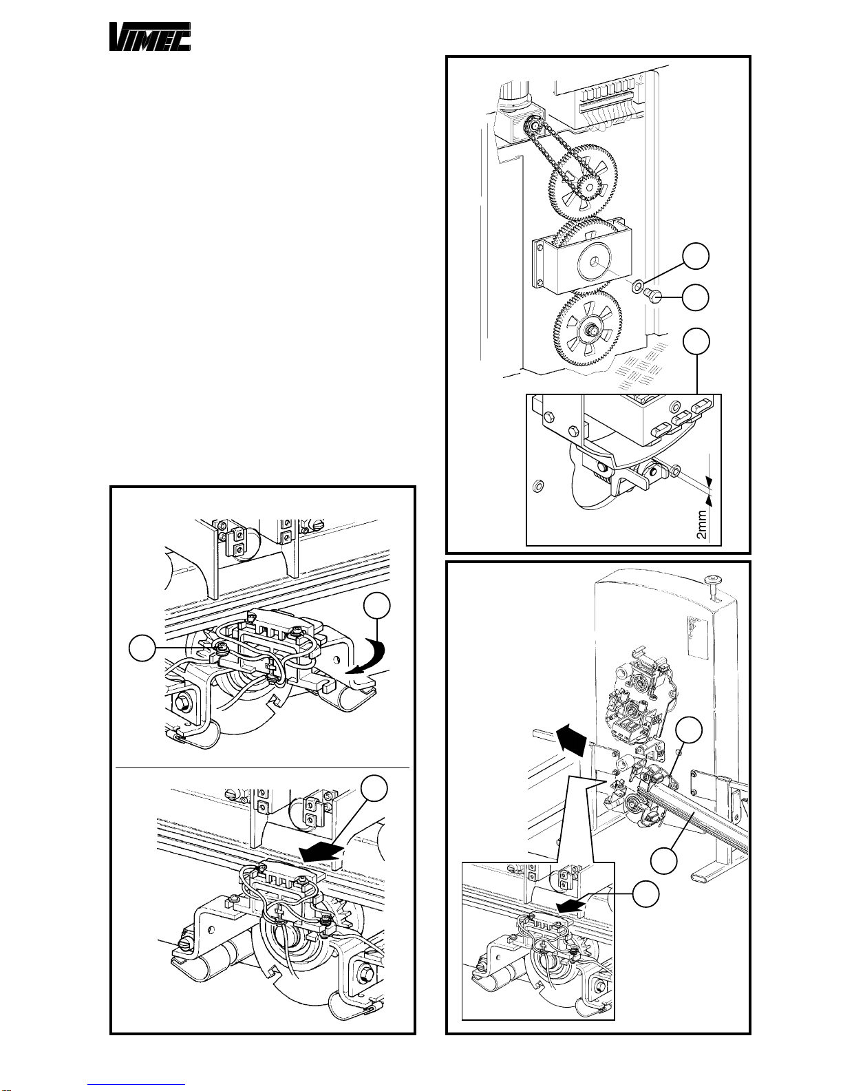
In order to facilitate the assembly operation for the wall
fastening (Fig. 10/a), it is advisable using the special
testfeet (Fig. 10/b) (ask the Vimec servicedepartment,
as they are not supplied) to insert on the guide instead
ofthe middle fastenings (almost 1-2everyramp).
NOTE: Before carrying out any machine handling test,
the connection (Fig. 10/a) must be fixed to the wall.
3) INSTALLING THE UPPER RAIL
- Position the spacing gauges (Fig. 11/a) (ask the Vimec
service department, as they are not supplied), on the
extremeedgesof thefirstpositionedguidesection (Fig.
11/b) (curve) and block them hard rotating the lever as
showninfigure (Fig.11/c).
- By loosening the handwheel (Fig. 12/a) and using a
spirit level (Fig. 12/b), position the support arm (Fig.
12/c)in perfectlyvertical position.Once theadjustment
hasbeendone,tightenthehandwheelhard(Fig.12/a).
- Position the upper guide (Fig. 13/a) on the spacing
gauges(Fig. 13/b)formerlypositioned, andafter having
checked the correct vertical sense (Fig. 13/c),
tightenthescreews(Fig.13/d)hard.
CAUTION: The couple securing the guide fixing
screws (Fig. 13/d) must be 6-7 daNm.
-Carryouttheassemblyofalltheguidesectionsremained,
proceeding in sequence as formerly described down to
thebottom of the scaleexcept the last one.If included
in the kit, insert the cable for push-button panles (Fig.
12/e)duringtheguidesconnection.
-When finished the assembly,retouch guideswithsup-
pliedblack paint andseal the screws(Fig.9/g) andthe
nuts (Fig. 9/h) of the busway junction.
FIG.10
FIG.11
FIG.13
FIG.12
a
c
ab
c
a
b
b
a
0±1
mm
ed
a
b
c

7602030
22
4)TROLLEY ASSEMBLY
-Position the structure kitted withtrolleysin the parking
zone at low plan.
- Completely fasten the screw M10x30 (Fig. 15/a) with
washer (Fig. 15/b) on the friction block in order to re-
leasetheupperplatformbalancefromthefrictiongroup;
thecorrect space is obtained when the clutchgroupis
about 2 mm clear from the swaying trolley (Fig. 15/c).
- Loosen the brush-holder fastening screw (Fig. 14/a)
and rotate it as indicated by the arrow (Fig. 14/b) or
pull the brushes backwords (Fig. 14/c) during the
introduction of the tube in the lower trolley.
NOTE:Duringthestagesdescribedasfollows,paymuch
attention to the correcto positioning of the slides (Fig.
17/f- 18/e) after havinglubricatedthem with grease.
- Insert the lower tube (Fig. 16/a) in the lower swaying
trolley (Fig. 16/b) remembering, if they have not been
slewed(Fig.14/b),todrawbackthebrushes(Fig.14/c).
- Insert the lower tube (Fig. 17/a) in the swaying trolley
(Fig. 17/b) making sure that the teeth of the dragging
pinion (Fig. 17/e) correctly match with the holes, until
carryingoutthejunctionoftheguidewiththeoneformerly
prearranged(Fig.17/c).
- Carry out the junction of the busway (Fig. 17/d) as
previouslydescribed.
FIG.16
FIG.14
FIG.15
a
b
a
b
c
b
SOLUTION"A"
SOLUTION"B"
c
a
c

7602030
23
- Insert the upper tube (Fig. 18/a) in the swaying trolley
(Fig. 18/b) and, with the help of the upper handwheel,
(Fig.18/c), insert it up to execution ofthejunction with
thetube (Fig. 18/d) previouslyprearranged.
-Incaseofformeropeningofthebrush-holdinggroup(Fig.
19), rotate it to the initial position.
-Manually press the unit(Fig.19/c) in the directionindi-
cated by the arrow (Fig. 19/d) till making both the
brushes re-enter at least 5 mm.
-Keepingthe unit (Fig. 19/c) pressed against the guide
(Fig.19/e) tightenhardthe screws(Fig.19/a and19/f).
CAUTION: Do not let the connection cables lean
out from the brush-holder overall dimensions to
guarantee the protection carter a perfect closing.
-Ifprovidedfixtheresistancewithtwoself-tappingscrews
to the brush-holder and connect the two cables to the
points “A” e “B” (Fig. 19).
- Screw-out the screw (Fig. 15/a) and its washer (Fig.
15/b) to couple back the clutch unit with the swaying
trolleyand remove the support feet(Fig.18/f).
FIG.19
c
d
b
a
A
c
B
f
ed
FIG.17
FIG.18
d
d
c
e
f
a
b
f
e
c
a
b
f
e

7602030
24
Once the guide assembly is through, for machine with
costant gradient lower than 20°, check the slant of the
wholeguide (maximum allowed error 1°)beforesarting
the machine up (see Fig. 20).
5)POWER SUPPLYUNITCONNECTION
-Connectthecables (positiveandnegative)to theproper
terminal of the busway fixed to the guide (Fig. 21/e -
Fig.21/f).
-Connect the electric power230 V 50 Hztothe suitable
socket (Fig. 21/c).
-At theend ofinstallation,give tensionthrough themain
switch (Fig. 21/d).
6)INSTALLERPUSHBUTTONCONNECTION
- Connect through suitable connection socket the in-
stallerpushbutton(Fig.22/a) (requireittoVimec service
department, as it is not supplied).
- By means of the (Fig. 22/b - Fig. 22/c) previously de-
scribed pushbutton panel controls take the structure
complete with trolley on the selected floor to continue
theassembly operations with total safety.
-Insertthespacinggauge(Fig.23/g) betweentheguides
andassemble the connection/foot (Fig. 23/a).
- After having correctly spaced the guides (Fig. 23/b -
Fig.23/c)with the spacing gauge (Fig. 23/g) and after
havingperfectlyplacedinverticalpositiontheconnection
(Fig.23/a), tighten the screws hard (Fig. 23/eandFig.
23/f).
NOTE: Lift the machine up to the 1st rigid connection, if
themachineisnothorizontal,screwin thescrewM10x30
(Fig. 15/a) with washer (Fig. 15/b) in the clutch unit in
order to clear the upper swaying trolley from the clutch
unit.
The correct space is obtained when the clutch unit is
about 2 mm clear from the swaying trolley (Fig. 15/c).
FIG.21
c
-e
+f
d
-a b +
FIG.22
c
b
a
- Raise the machine a bit, in order to reset it.
- Slack the screw (Fig. 15/a) and its washer (Fig. 15/b)
to couple back the clutch unit with the swaying trolley.
FIG.20
2
1
2
3
3
POS. DRIVINGTORQUE
(daN x m)
1
2
3
2,5
6,0
4,5
3

7602030
25
7)CONNECTION FEET FINALASSEMBLY
After having done a test operation to make sure that
everythinghasbeen correctlyassembled,it isnecessary
tofix the supportfeet to thegroundand theconnections
(wherepossible)to the wall.
According to the type of foot foreseen in the assembly
diagram, fix it hard as shown in the following examples
(Fig.24-25-26-27).
In case of step-fixing foot (Fig. 27), drill the same steps
and block it all with the issued screws (Fig. 27/a).
After the fixing operation, tighten the screws hard (Fig.
27/b).
In case of flag-support foot (Fig. 26), drill in the fixing
points and block it all with the issued screws (Fig. 26/
a).
Tensionthe foot (Fig.26/c) introducing thethreadedbar
in the proper holes (Fig. 26/b) and screwing in the nut
and the counternut (Fig. 26/d) up to reaching of the
tensioning.
To avoid guide inclination changings (Fig. 28/a) in the
future, it is necessary to drill a hole (Fig. 28/b) on the
connection joint (Fig. 28/c), after having furthuerly
checkedthecorrect assembly,andthen insertablocking
peg (Fig. 28/d) in that same hole.
FIG.24
FIG.25
FIG.23
c
g
b
a
f
d
e

7602030
26
FIG.27
FIG.26
a
a
b
d
b
db
c
a
8)BARS ASSEMBLY
Mountthe bars supports (Fig.29/b)on the machine fra-
me(Fig. 29/a)makingthe correspondingreference pins
(Fig. 29/c) match.
Tighten the bars with the proper issued screws (Fig.
29/d).
Then, proceed to connection of the electrical card
sheaths.
8.1) Indipendent bars - Connected bars
Connectthe cable inthelower part ofthe bar (Fig. 29/e)
with the footboard interblock system (Fig. 29/f).
8.2) Retractile bars
Connectthe lever in the lower part ofthebar (Fig. 29/g)
with the screw and the self-locking nut (Fig. 29/h).
FIG.28
c
ab
d
FIG.29 d
a
b
dc
f
e
d
a
b
g
h
dc
c
c

7602030
27
9)ASSEMBLINGTHEPLATFORMWITHMOTORIZED
ACCESS FRONTAL (B.I. - B.C. - B.R.)
On customer request it is possible to have a footboard
withoverturning front side(Fig.30/a).
Sucha footboard permits, on the lower flooronly,toac-
cess/godown perpendicularly to the machine.
9.1) Assembling the platform
a) Remove the top plate from the platform by undoing
therelative screws.
b) Make sure that the two platform supports, fixed by a
wedgeand aplasticclamp, areinthe assemblyposition
(Fig.33/a/b).
c) Fit the platform, keeping it vertical and turning it
through 90° as shown in (Fig. 31).
d) Fix the platform to the frame using the relative M8
flatheadscrews (Fig. 31/a)
e) Fix the two microswitches of the sensor base (Fig.
32/a)to the platform, passingthembetween the sensor
baseand the platform frame (Fig.32/b).
If necessary, back off the sensor base tripping cams
(Fig. 32/c) to allow the microswitch to pass.
Then restore the original positions so that the sensor
base trips the microswitches when it is pressed.
FIG.30
a
FIG.31
a
c
b
a
FIG.32
a
f)Connectthe lateralguard boardoperating cables(Fig.
34/f)andfrontal (Fig. 34/e) to the fork (Fig. 34/b).
-
Tighten
with nut and screw.
- Insert the eccentric (Fig. 34/h) with handling belt (Fig.
34/g),frontchute onthe specialpin(Fig.34/i)andblock
withseeger(Fig. 34/m).
B. R.: fix the cable (Fig. 34/f) already present on the
side bar chute with special screws.
- Fix the cable eye (Fig. 34/e) to the eccentric (Fig. 34/
h) by screw, nut and lock nut leaving the necessary
clearance for the rotation of the eye itself.

7602030
28
FIG.33
FIG.34
125
b
a
e f
b
d
c e
m
g
h
i
c
a
b
d

7602030
29
Proceeds to check the proper working of the front ac-
cess chute:
- Check the angle between the chute (in working posi-
tion)andthe footboard is 90° (Fig. 35).
- Check the front access micro chute intervenes with a
maximumrotation of 30°of the samechutewith respect
to the working position as in Fig. 35.
-If the guards arenot opened or closedcorrectly,adjust
FIG.35 FIG.36
ab
tothespecified positionusingtheregisterfork (Fig.34/b).
g) Replacethe top plateonthe platform usingthe relati-
vefixing screws.
h) Remove the wedge and the plastic clamp (Fig. 33/c/
d) used to keep the platform horizontal during the
adjustmentsfrom the platform supports.
i) Tighten with a driving torque of 4 daN ± 0,1the dowel,
the nut and the locknut (Fig. 36/a,b).
FIG.37
c
a
b
d

7602030
30
10)ASSEMBLING THEPLATFORM
a) Remove the top plate from the platform by undoing
therelative screws.
b) Make sure that the two platform supports, fixed by a
wedgeand aplasticclamp, areinthe assemblyposition
(Fig.37/a/b).
c)Fittheplatform,keepingitverticalandturningitthrough
90° as shown in (Fig. 38).
d) Fix the platform to the frame using the relative M8
flatheadscrews (Fig. 38/a).
e) Fix the two microswitches of the sensor base (Fig.
39/a)to the platform, passingthembetween the sensor
baseand the platform frame (Fig.39/b).
If necessary, back off the sensor base tripping cams
(Fig. 39/c) to allow the microswitch to pass.
Then restore the original positions so that the sensor
base trips the microswitches when it is pressed.
f) Connect the lateral guard board operating cables to
the relative bar actuators, passing them around the pin
(Fig.40/a).
If the guards are not opened or closed correctly, adjust
to the specified position using the register fork (Fig.40/
b).
g) Replacethe top plateonthe platform usingthe relati-
vefixing screws.
h) Remove the wedge and the plastic clamp (Fig. 37/c/
d) used to keep the platform horizontal during the
adjustmentsfrom the platform supports.
i) Tighten with a driving torque of 4 daN ± 0,1the dowel,
the nut and the locknut (Fig. 41/a,b).
FIG.38
c
b
a
FIG.39
a
FIG.40
a
b
125
FIG.41
ab
a

7602030
31
11) TEMPORARYASSEMBLY OF THEDOME
FOR INSTALLATION CHECK
On completion of the machine mechanism assembly it
isnecessary to carry outthe temporary assembly ofthe
upperdome.
Tocarry outthisassembly itonly takesverticallyrotating
theprearranged-to-this-aimbrackets(Fig.42/a)andfixing
thedomeovermachine(Fig.42/b).Carryouttheelectrical
connections and then the following checks described
below.
12)INSTALLATIONCHECKS
- Check that the operating mode setting switch (JB22 -
JB23) is set as appropriate to the system type (RH or
LH).
- Check that the jumpers are according to the electric
system.
- Check that all the lifts and microswitches working are
correctly positioned,consulting the electrical system
diagramsprovided.
- Verify also all controls correct working.
a) Safety devices
Checkthaton contact with an obstacle, the anti-impact
andanti-shearingsensors stop the lift and allow it tobe
startedinthe opposite travel direction.
Checkthat the stopping positions at the floorsprovided
by the limit switches are to requirements.
b) Electromagnetic brake
The electromagnetic brake on the motor must stop the
liftwhen fully loadedbeforethe overlimits stopdevice is
tripped.If necessary, replace the wholebrake.
c) Drive mechanics
Checkthat the teeth of thedrivesprocket and the nylon
wheels on which the lift runs are not worn or damaged.
There must be no grooves or flattening on the wheels.
Check that the chain is not worn.
d) Safety gear
Check that the hook device is free to operate without
frictionorexcessivebacklashes andthatittrips thesafety
microswitch correctly.
To check operation of the safety gear, proceed as fol-
lows:
-Movethe stairlift 1-2 metres from the floor.
- Disconnect the power supply by turning the master
switch to OFF.
-Remove the protectivepanel(Fig. 1/d).
- Press the safety ear hook with a wooden/plastic rod.
CAUTION: Keep well away from all un- pro-
tected moving parts.
FIG.42
- Restore the power supply and press the down button
until the hook engages. The stairlift will stop when the
safety microswitch is pressed by the hook.
-Resetthe safety gear by moving the stairlift upwardin
manualmode (see point 7.6).
e) Stability of the rail
Check all the fixing screws o the connections to the
mountsand all expansion plugs present.
f) General checks
Check all moving parts, the guards, labels and signs.
Checkthebatteries condition and the indicator lights of
both the power supply units.
b
a
a

7602030
32
FIG.43
FIG.45
ac
13)ROLLS FORCURVEREGULATION
On the less sloping curve (Fig. 43/a) place till touching
theguide, therollsfor curve(Fig. 43/b). Atthe endofthe
regulation tighten the rolls fastening screws (Fig. 43/c)
with a 2 daNm couple.
Thisregulationwill bekeptalso forothercurvesonwhich
thecontact willbe guaranteedby properthickening(Fig.
43/a)(optional).
Makesure the machineis properlyworking without any
joltsand vibrations in curve.
Onthe contrary adjust the curve thickening notonlevel
ground.
14)SLIDES SUPPORTS ADJUSTMENT
Adjustthe slides support usingthescrews (Fig. 44/a) in
order to obtain a 0,5 ± 0,5 mm distance between slide
andguide(see Fig. 44).
15)GUIDE THICKENING (OPTIONAL)
Incaseofcurveswhererolls(Fig.45/b)shouldnottouch
the guide (Fig. 45/c) it is necessary to fix proper thick-
ening profiles as shown in Fig. 45/a.
Thickening then must be chosen in order to reduce to
minimumthe rollsclearance(Fig. 45/b)guide clearance
(Fig.45/c) withoutcausing excessivefrictionsor strains.
b
a
b
a
b
c
b
FIG.44
a

7602030
33
16) LIMIT STOP CAMS AND INTERMEDIATE STOP
ASSEMBLY
- Bring the stairlift to the stop position (Fig. 46/a - 47/a
- 48/a) tracing on the tube guide the centerline axis of
the machine (Fig. 46/b - 47/b - 48/b).
-Move the machine.
- In case of upper (Fig. 46/a) or lower (Fig. 48/a) stop,
assemble the proper limit switch cam (Fig. 46/e - 48/
e) using screws, nuts and washers (Fig. 46/c - 48/c)
and support (Fig. 46/d - 48/d) issued.
- Block the cam (Fig. 46/e - 48/e) on the guide at a 30
mmdistance from the machine middleaxispreviously
traced.
- Eventually, secure all the screws.
- Nel caso di fermata intermedia (Fig. 47/a) assembly
the support (Fig. 47c) on the tubular (Fig. 47/d) by
meansof two dowels M8x30 (Fig. 47/e).
Assembly the cam stiffening bracket (Fig. 47/f), the
spacer (Fig. 47/g), and the bracket cam fixing bracket
(Fig.47/h)with screws TSPCE M8x16 (Fig. 47/n) and
TSPCEM8x35(Fig. 47/i).
Assemblythecam (Fig. 47/l) with N°2 screws TSPCE
M5x20(Fig.47/m).
Placethecam at a distance of 177 mm fromthelower
side of the upper guide tube, and at 30 mm from the
machinecenterlineaxistracedbefore
(Fig. 47/b).
- Eventually, secure all the screws.
FIG.46
Upper limit stop cam
FIG.48
Lower limit stop cam
FIG.47
Intermediatestop cam
30
177
m
d
e
c
f g e
l
h
i
n
d
e
c
fb
a
c d
c
d
c
c
e
c
e
d
c
cc
d
a
be
30
30
a
b
e

7602030
34
FIG.50
17)CAMPLACEMENT AND EXTRARUN
PLATESCHECK
Before executing the machine final test, it is necessary
tocheck the cams(Fig.49/a-50/a) and extra-rundishes
(Fig.49/b-50/b)correct placementbothontheupper and
lowerfloor.
Suchplacement resultsascorrect ifthe heights appear-
ingon the drawings are verified (see Fig.49and 50).
18) FINAL TESTING
Supply power to the system and perform the
following functional checks:
- Load test:
-Load the lift with 1.1 times theratedload stated on the
nameplate.
- Send the lift up and down several times, checking its
stability on the rail.
- Test for a machine with guide sections with
inclination lower than 20°
-Take the machineinthe area superiorto 25°, verifythe
camoperation rollis0,5÷1,5 mmfar from thecam (see
Fig.52).
- In case it is necessary moving the roll closer to or
away from the cam the grub screw must be loosened
(Fig. 55/a) and the friction wheels hub must be turned
(Fig. 55/b). When the registration is made tighten the
grub screw (Fig. 55/a) with loctite.
- Then, take the machine in the area with inclination
lower than 20°, load a 250 kg weight with barycentre
150 mm far from the end (see Fig. 51).
- Verify the machine has not an inclination superior to
2°.
- Preliminary checks
-Perform the checksdescribed in point6.1on page8of
theUse and Maintenance Manual.
- Safety gear test
- Test the safety gear as described in Section 9, point
“d".
-Verify foot-board, independent bars, retractile bars
interlock.
With the low side bar in stand-by position check that
the foot-board remains blocked whether it is in working
or in stand-by position.
Forthe motorized foot-board versions itisnecessary to
carry out the same check taking care of releasing the
actuatorfoot-board by pressing thereleasebutton (Fig.
12/a- section "Operation and Maintenance").
- Check on fixing of the rail
-Check that therailis positioned inaccordance with the
dimensionsstatedin theinstallationdrawing (orsystem
layout) supplied with the lift.
- Check that all the fixing screws of the connections to
themountsorany expansionplugsarestable andfirmly
tightened.
FIG.49
a
b
25
15
a
b
25
15
HIGH
LEVEL
LOW
LEVEL
FIG.51
150 mm
250 kg

7602030
35
FIG.52
FIG.53
0,5÷1,5mm
19)FITTINGTHEBODYWORKSECTIONS (Fig. 53-54)
Firmlyassemblythedome(Fig.54/b),removingthesupport
feet (Fig. 54/a). After having rotated these latter towards
the inside, fix the dome to the machine using the proper
screws formerly used to fix it to the support plates (Fig.
54/a).
Fit all the bodywork sections as on the overall drawing
suppliedwith the machine,paying attention nottocrush
any electric cables or working components.
20)TERMINALS ANDPLUG ASSEMBLY
- Mount by pressure the proper issued plugs (56/a) on
eachguides connection.
-Mount theproperconnection profiles(Fig.57/a) onthe
guidesupper and lowerterminalsections. To carryout
such assembly it only takes introducing the end plugs
(Fig.57/b) in theguidesand lock themwith the screws
(Fig. 57/c) issued.
-Eventually,mountthe connection profile (Fig.57/a)by
pressure as shown in Fig. 57.
FIG.54
b
a
FIG.55
FIG.56
FIG.57
b
aa
a
c
b
a
b
a
b
Table of contents
Other vimec Fitness Equipment manuals