vimec ROBY T09 User guide

01-09-2017DATE _________ APPROVED _____________
Via Parri, 7 (I) - 42045 Luzzara (RE)
Tel.0522/970666 r.a.- Fax.0522/970919
Sito web: www.vimec.biz
MONTASCALE MOBILE A CINGOLI
T09 "ROBY" 130 kg
USO E MANUTENZIONE Pag. 03 - 22
CATALOGO RICAMBI Pag. 23 - 38
7 5 1 1 0 1 0 / A
CODICE MANUALE
La VIMEC si riserva, al ne di seguire l'evoluzione tecnica,di apportare modiche e cambiamenti ai suoi prodotti
in qualsiasi momento.
Istruzioni originali
7511010
VIMEC S.r.l.
DICHIARAZIONE DI CONFORMITA’ "CE"
"CE" DECLARATION OF CONFORMITY
Il costruttore:
The manufacturer:
Via Parri n. 7, 42045 Luzzara (R.E.) ITALY
Tel. 0522/970666 r.a. Fax 0522/970919
dichiara sotto la sua sola responsabilità che il montascale mobile a cingoli per il trasporto di
persona in carrozzina modello:
declares under its own responsability that the Stairclimbers for the transport of person on wheelchair model
T09
è conforme alle seguenti Direttive Europee:
comply with the following European Directives
• Direttiva 2014/30/UE "Compatibilità Elettromagnetica"
Directive 2014/30 "Electromagnetic compatibility"
• Direttiva 93/42/CEE "Dispositivi Medici" (Categoria I) come modicata dalla
Direttiva 2007/47/CEE
Directive 93/42 "Medical Devices" (Catecory I) as modied by the Directive 2007/47
L'Amministratore delegato
The President
Ing. Giuseppe Lupo
Luzzara, 01/10/2016
7519010/A

3
7511010/A
INDICE DEL MANUALE
1. Dati di identicazione macchina e costruttore Pag. 4
2. Servizio assistenza Pag. 4
3. Descrizione della macchina Pag. 5
4. Caratteristiche tecniche Pag. 7
5. Usi previsti e non previsti della macchina Pag. 8
6. Trasporto Pag. 10
7. Preparazione della messa in servizio Pag. 10
8. Messa in servizio ed uso giornaliero Pag. 11
9. Manutenzione Pag. 16
10. Vibrazioni - Rumore aereo della macchina Pag. 17
11. Informazioni sullo smaltimento di sostanze e parti della macchina Pag. 17
12. Istruzioni brevi per effettuare correttamente le operazioni di salita e
discesa con il montascale mobile a cingoli Pag. 18
13. Reversibilità degli attacchi di sicurezza Pag. 20
14. Caratteristiche carica batterie Pag. 22
USO E MANUTENZIONE
PER LAVORARE CON SICUREZZA
ATTENZIONE
Questo simbolo accompagna alcune istruzioni essenziali per la sicurezza
La osservanza di queste istruzioni non esime dal rispetto di tutte le rimanenti.
Leggere con attenzione questo manuale prima di procedere al montaggio, all’avviamento, all’uso e manutenzione
della macchina.
La migliore prevenzione per gli infortuni è l’attenzione e la prudenza durante l’uso della macchina.
Rispettare le informazioni fornite dalle targhette di ogni tipo applicate alla macchina.
Provvedere immediatamente alla sostituzione delle targhette danneggiate.
L’intervento sulla macchina per operazioni che non siano di normale uso, è riservato ad operatori professionali.
Rispettare il livello di competenza indicato per le diverse attività con riferimento ai seguenti simboli:
O Operatore addestrato
OC Operatore addestrato provvisto di specica competenza
OS Operatore specializzato incaricato dal fabbricante
La macchina deve sempre essere condotta da una persona ADULTA, informata di tutte le funzioni operative
e delle precauzioni previste dal presente manuale.
4
servoscale
I - 42045 LUZZARA (RE)
Via Parri, 7 - Tel. 0522/970666 - Fax. 0522/970918
Tipo/Type/Type/Typ/Tipo T09
Matr./Num./Serial Nr/Fabrik. Nr/Matr N° _ _ _
Anno Fabbr./Produit en/Years/Bajahr/Año _ _ _ _
Port./Capac./Load/Tragfah./Carga util Kg 130
Alim./Alim./Power/Spe./Alim. (V/A/Hz) 110 230 / 3 / 50
Basam./Carter/Base/Unterg./Basam. Kg 37
Man./Guidon/Handl./Lenk./Manil. Kg 10
Matr./Num./Serial Nr/Fabrik. Nr/Matr.
_ _ _ _
Matr./Num./Serial Nr/Fabrik. Nr/Matr.
_ _ _ _
Port./Capac./Load/Tragfah./Carga util
130 kg
7511010/A
1) DATI DI IDENTIFICAZIONE MACCHINA E COSTRUTTORE
2) SERVIZIO ASSISTENZA
TIMBRO RIVENDITORE E RIFERIMENTO PER L'ASSISTENZA TECNICA AUTORIZZATA
7519010/A 7519010/A

5
a
b
ab
b
d
c
a
e
dc
c
c
f
7511010/A
FIG. 1
FIG. 3
FIG. 2
3) DESCRIZIONE DELLA MACCHINA
3.1) Descrizione
Basamento -Fig. 1/a
Si compone di:
- struttura portante in lega leggera;
- protezioni in plastica.
Contiene:
• motore;
• organi di trasmissione;
• cingoli;
• ruote per il trasferimento rapido in piano;
• impianto elettrico;
• batteria;carica batteria bordo macchina.
Sul pannello comandi del basamento sono posti:
- leva per lo sgancio meccanico del timone (Fig. 2\a);
- spina per carica batteria (Fig. 2\b);
- connettore elettrico bipolare per il timone (Fig. 1/c);
- pulsante comando avanti/indietro basamento (Fig.
2/d);
- led indicazione stato di carica batteria (Fig. 2/c).
Timone -Fig. 3/a
Il timone ha le funzioni di aggancio della carrozzina
e di manovra dell'intera macchina sia sulle scale che
sui pianerottoli.
Sul timone sono alloggiati i principali comandi per la
conduzione del montascale mobile a cingoli.
Contiene:
- sistema di sicurezza meccanico di aggancio carroz-
zina (Fig. 3/c);
- traversa di aggancio carrozzina con blocco meccanico
regolabile in altezza (Fig. 3/d);
- traversa di appoggio ruote della carrozzina (Fig. 3/e);
- poggiatesta regolabile (Fig. 3/b);
- connettore elettrico bipolare per il basamento (Fig. 3/f).
Il pannello comandi posto fra le maniglie (Fig. 4/f)
contiene:
- pulsanti di manovra avanti/indietro (Fig. 4\a);
- stop di emergenza (fungo rosso) (Fig. 4\b);
- indicatore visivo di pendenza (Fig. 4\c);
- spia stato di carica della batteria (Fig. 4\d):
·
Batteria scarica
lampeggia;
·
Motore bloccato
lampeggia con
frequenza doppia
rispetto alla batteria
scarica.
- chiave "ON/OFF" di accensione/spegnimento (Fig.
4/e).
Carica batteria bordo macchina
Ha la funzione di ricaricare la batteria dopo l’utilizzo del
montascale mobile a cingoli e di mantenere lo stato di
carica quando il montascale mobile a cingoli non viene
utilizzato.
6
a
c
b
a
a
b
e
c
f
f
d
a
7511010/A
3.2) Principali misure di sicurezza contro i rischi di
natura meccanica
Aggancio carrozzina al timone
- Pomelli di blocco delle leve di aggancio con richiamo
a molla (Fig. 6\a).
- Pomolo di blocco della traversa di aggancio carrozzina
(Fig. 6\c).
- Volantino di serraggio (Fig. 6/b).
3.3) Principali misure di sicurezza contro i rischi
di ribaltamento
- Indicatore ottico di massima pendenza superabile
(Fig. 4\c).
3.4) Targhe di avvertimento e di obbligo
La macchina è provvista di targhette adesive di
avvertimento e di obbligo.
3.5) Posizione di lavoro
In tutte le fasi operative il conducente deve trovarsi dietro
al timone impugnando saldamente le maniglie (Fig. 4/f).
3.6) Stato di fornitura
-Basamento (Fig. 1\a).
- Timone di manovra (Fig. 3\a).
- Cavo di carica (Fig. 5/a).
3.7) Direttive di riferimento
La macchina è conforme alle seguenti norme:
DIRETTIVA 2007/47/CEE
Concernente i dispositivi medici.
DIRETTIVA 89/336
Compatibilità Elettromagnetica 2014/30/UE
FIG. 5
FIG. 6
FIG. 4
7519010/A 7519010/A

7
7511010/A
4) CARATTERISTICHE TECNICHE
- Impianto di trazione
Riduttore a vite senza ne irrever-
sibile
Cinghia dentata con cingoli in
gomma
Pulegge motrici
Sistema meccanico tendi cinghie
Ruote folli per il trasferimento in
piano
- Prestazioni
Senso di marcia
Velocità (salita/discesa)
Capienza
Portata
Caratteristiche geometriche della
scala
- Condizioni ambientali
Temperatura
Umidità
- Ingombri
Corpo macchina
Timone
- Massa
Corpo macchina
Timone
- Impianto Elettrico
Motore c.c. magneti permanenti
Assorbimento
Carica batteria bordo macchina
Batteria sigillata con elettrolita
gelatinoso
Tempo di ricarica batteria
Fusibile
- Comandi
Pulsante marcia (avanti/indietro)
temporizzato
Pulsante di stop di emergenza a
ritenuta
- Segnalazioni
Segnalatore luminoso dello stato di
carica della batteria
Segnalatore ottico di pendenza a
gravità
ROBY 130 kg
Rapporto 1/37
HTD-8M
z=36
n° 4 ruote su cuscinetti a sfere
Avanti/Indietro
5 m/min.
1 persona con carrozzina
130 kg
Vedi Fig. 8
0° ÷ +45°C
massimo 90%
Vedi Fig. 7
Vedi Fig. 7
kg 37
kg 10
24V
25 A
110÷230V c.a.50 Hz, 24Vc.c.2A
2x12V 12 Ah
8 ore a batteria completamente
scarica
40 A
Ritardo 1 secondo
8
950
1390
950
400
310
1100
700
7511010/A
FIG. 7
5) USI PREVISTI E NON PREVISTI DELLA MACCHINA
5.1) Usi previsti
Il montascale mobile a cingoli Mod. T09, è destinato al trasporto di persone disabili in carrozzina manuale di
tipo a ruote grandi posteriori su scale aventi le seguenti caratteristiche:
- Ambiente: Interno/esterno
- Gradini: Paralleli, senza rivestimenti
- Pendenza: Massimo 35° (Fig. 8/α)
- Alzata: Massima 180 mm, minimo 100 mm (Fig. 8/A)
- Raggio di curvatura prolo gradino: Compreso tra 0 e 20 mm (Fig. 8/R)
- Conduttore:
Sempre presente e con le seguenti caratteristiche:
Persona adulta, idonea sicamente e psichica-
mente, a conoscenza del funzionamento dell'ap-
parecchio e delle istruzioni di uso e manutenzione.
5.2) Usi non previsti
Usi non previsti Inconvenienti
Impiego su scale con pendenza superiore a 35°: Instabilità, slittamento cingoli
Impiego su gradini con alzata superiore a 180 mm: Instabilità, slittamento cingoli
Impiego su gradini con alzata inferiore a 100 mm: Slittamento cingoli
Impiego su gradini con raggio di raccordo bordo scalino superiore a 20 mm
: Slittamento cingoli
Guida da parte di un operatore non idoneo: Instabilità
Trasporto carrozzine EN12184 non idonee A ÷ B
Trasporto di persone o cose non sedute in carrozzina
Impiego su scala in presenza di acqua, neve o ghiaccio: Instabilità, slittamento cingoli
Impiego su superci bagnate o in caso di pioggia: Avaria dell'impianto elettrico
Impiego su scala con gradini non paralleli: Instabilità, ribaltamento laterale
ATTENZIONE: NON APPORTARE MODIFICHE PER OGNI TIPO DI USO
7519010/A 7519010/A

9
625
= =
160
b
a
a
7511010/A
6) TRASPORTO
6.1) Movimentazione
Il trasporto della macchina smontata può avvenire manual-
mente per brevi tratti o per operazioni di carico/scarico.
Il basamento deve essere trasportato utilizzando le
apposite maniglie alle sue estremità (Fig. 9\a e b).
Massa del basamento completo di batteria:
- kg 37
Massa del timone:
- kg 10
Il sollevamento manuale del basamento, per motivi
ergonomici, potrebbe richiedere l’intervento di due
persone.
6.2) In caso di non utilizzo
- Ricoverare la macchina in un ambiente asciutto.
- Possibilmente proteggere la macchina dalla polvere
ricoprendola.
- Non lasciare la macchina esposta agli agenti atmo-
sferici.
- Mantenere la macchina sotto carica.
6.3) Posizione del centro di massa (Fig. 10\a)
Si trova tra manubrio e basamento, considerando in
posizione di blocco timone e basamento.
7) PREPARAZIONE PER LA MESSA IN SERVIZIO
7.1) Fasi preliminari all’installazione
Prima di procedere all’installazione, leggere atten-
tamente il presente manuale.
Apertura dell’imballo
- Tagliare con una lama la pellicola protettiva. Non
strappare né riscaldare in alcun modo l’imballo.
-
Aver cura di non grafare le superci della macchina
.
- Pulire la macchina eliminando ogni residuo di imballo
e polvere.
7.2) Smaltimento del materiale di imballo
Rivolgersi ad una Ditta autorizzata per il ritiro e lo
smaltimento dei residui di imballo.
7.3) Controlli preliminari
Controlli da eseguire prima della messa in servizio.
Competenza: OS - Operatore specializzato incari-
cato dal fabbricante.
ORGANO CONTROLLATO:
RISULTATO DEL CONTROLLO
Timone:
- Aggancio sicuro del timone a necorsa (Fig. 11):
- Pomoli (Fig. 6/a):
Scorrevolezza, ritorno sicuro in posizione di blocco.
- Cinture di sicurezza:
Efcienza dell’organo di aggancio/sgancio.
- Comandi:
Avviamento congruente ai comandi;
Corretta temporizzazione dei comandi;
Efcienza dell'arresto di emergenza (Fig. 4/b).
- Segnalazioni:
Efcienza del segnalatore di carica batteria (Fig. 4\d)
;
Efcienza del segnalatore di pendenza ottico (Fig. 4\c)
.
Corpo macchina:
- Carica batteria:
Tensione e frequenza di rete conformi ai valori previsti
nel paragrafo 7.5.
- Efcienza leva sgancio timone (g14/b)
- Efcienza guscio di protezione (g.12/b)
7.4) Condizioni ambientali del luogo di utilizzo
- Temperatura: Da 0 °C a +45 °C
- Umidità: Max 90%
FIG. 9
FIG. 10
10
a
b
a
b
a
b
b
a
c
c
7511010/A
7.5) Allacciamento elettrico
Il cavo di alimentazione del carica batteria è del tipo
3x0,75 mm2 (numero poli x sezione).
L’utente dovrà collegare il carica batteria ad una linea
conforme alle norme vigenti per gli impianti elettrici ad
uso civile, dotata di un adeguato interruttore differen-
ziale.
Dati del carica batteria:
- Tensione nominale (IN): 110÷230 V c.a.
- Frequenza (IN): 50/60 Hz
- Tensione nominale (OUT): 24 V c.c./2A
8) MESSA IN SERVIZIO ED USO GIORNALIERO
8.1) Montaggio ed aggancio del timone
a) Agganciare il timone (Fig. 11/a) sull'apposito tubolare
(Fig. 1/b) ricavato sul basamento.
b) Inclinare il timone (Fig. 12/a) come indicato dalla
freccia (Fig. 11/b) no ad agganciarlo al basamento.
c) Una volta agganciato il timone (Fig. 12/a), proteggere
la leva di sgancio premendo sul guscio (Fig. 12/b).
ATTENZIONE: assicurarsi che il guscio di sicu-
rezza sia in posizione. In questa conformazione, la
presa dei contatti elettrici è innestata ed il timone è
bloccato nella sua posizione di lavoro. Con la chiave
inserita (Fig. 4/e) si abilita l'accensione della macchina;
i pulsanti (Fig. 4/a) posti sul timone permettono di far
funzionare i cingoli avanti-indietro. Se il guscio rosso
non è in posizione, la macchina non dà il consenso
alla marcia.
8.2) Sgancio del timone
Per sganciare il timone (Fig. 13/a) è necessario solle-
vare il guscio di sicurezza di colore rosso (Fig. 13/b) e
successivamente mentre si preme sul pedale di sgancio
(Fig. 14/b) si spinge in avanti il timone (Fig. 14/a) come
indicato dalla freccia (Fig. 14/c).
FIG. 11
FIG. 13
FIG. 12
FIG. 14
7519010/A 7519010/A

11
b
a
f
b
d
c
a
c
a
b
a
c
e
bd
7511010/A
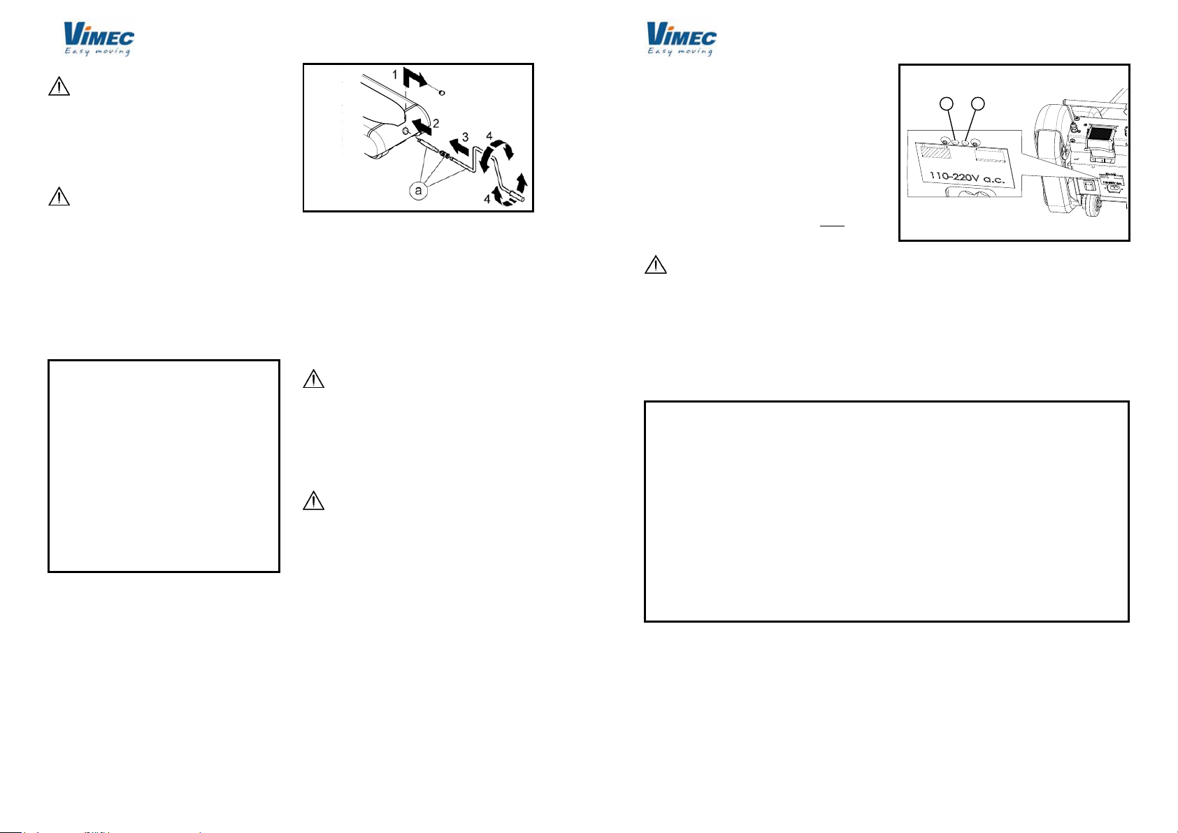
8.3) Aggancio della carrozzina
a) Inserire la chiave (Fig. 15/a) di attivazione del mon-
tascale nell'apposita sede (Fig. 15/b).
b) Con una leggera pressione sul timone, operazione
che mette in funzione le ruote ausiliarie, portare il
montascale sotto la carrozzina (Fig. 16/a), la quale
deve avere le ruote frenate.
c) Impugnando il timone (Fig. 13/a), con il piede eser-
citare una leggera pressione verso l'alto (Fig. 13/c)
sul guscio (Fig. 13/b) in modo da sollevarlo.
d) Premere il pedale (Fig. 14/b) verso il basso in modo
da sganciare il timone (Fig. 14/a) e, spingendo in
avanti (Fig. 14/c), accostarlo allo schienale della
carrozzina (Fig. 16/c).
FIG. 18
FIG. 16
FIG. 15
e) Tirare (Fig. 17/b) il pomello (Fig. 17/a) posto sulla
faccia posteriore del timone, e far scorrere i bracci
(Fig. 17/c) no a portarli sotto le impugnature della
carrozzina (vedi Fig. 16).
N.B.: Eseguire questa operazione impugnando la
traversa come indicato in Fig. 17/d.
f) Registrare in larghezza i gruppi di bloccaggio (Fig.
18/a) in base alla larghezza delle maniglie della
carrozzina: svitare la manopola (Fig. 18/b) e sposta-
re lateralmente il gruppo di bloccaggio (Fig. 18/c).
Questa operazione deve essere effettuata prima da
un lato e poi dall'altro.
g) Con una mano afferrare il pistoncino (Fig. 19/a)
sollevandolo. Fare poi passare il gancio (Fig. 19/b)
ed agganciarlo al telaio della carrozzina (vedi Fig.
16/e), quindi rilasciare il pistoncino ed assicurarsi che
il gancio non possa aprirsi, questa operazione deve
essere effettuata prima da un lato e poi dall'altro.
Quindi serrare le manopole (Fig. 18/b).
FIG. 17
12
a
b
7511010/A
IMPORTANTE: non si devono assolutamente
agganciare maniglie od altre parti che siano in qualche
modo slabili dal complesso della carrozzina.
h) Con una modesta trazione sul timone riportarlo indie-
tro (Fig. 11/b) no ad agganciarlo all'unità motrice.
Per questa operazione si può far leva con il piede
sulla staffa (Fig. 16/f).
i) Con il piede chiudere il guscio (Fig. 12/b) di sicurezza.
ATTENZIONE: chiudere sempre il guscio di sicu-
rezza prima di effettuare qualsiasi movimento manuale
o motorizzato
l) A questo punto la macchina è pronta alla marcia.
Premere il pulsante di marcia, se l'ausilio si attiva
le connessioni sono attive, se l'ausilio non si muove
vericare:
- Pulsante di stop
-Chiusura guscio di sicurezza.
m)
Premendo verso il basso sul timone si attivano le ruote
ausiliarie con le quali ci si porta all'inizio della rampa
per effettuare la salita o la discesa (Fig. 27 e 29).
ATTENZIONE: allacciare la cintura di sicurezza
prima di affrontare la rampa di scale.
ATTENZIONE: con persona a bordo, anche nei
tratti piani, impugnare sempre saldamente con entram-
be le mani il timone.
8.4) Preparazione per la marcia
a) BATTERIA:
Vericare lo stato della batteria, dopo aver mon-
tato la macchina, azionando per un momento la marcia
con macchina scarica (senza nessuno a bordo).
L’utilizzo della macchina quando il led indi-
catore ha assunto la colorazione lampeggiante
potrebbe danneggiare la batteria.
b) SEGNALAZIONI:
Non movimentare il montascale mobile a
cingoli prima di aver provato il funzionamento del
segnale visivo di avvertimento per il ribaltamento.
Se l’avvisatore visivo non funziona, NON UTI-
LIZZARE il montascale mobile a cingoli! Chiamare
subito un tecnico autorizzato VIMEC.
c) EMERGENZE:
Vericare il funzionamento dello STOP di
emergenza (pulsante rosso sulla plancia del timone).
- Premere il pulsante: i comandi di marcia devono
risultare disattivati.
- Ripristinare il pulsante tirandolo verso l'alto.
Se lo STOP di emergenza non funziona, NON UTI-
LIZZARE il montascale mobile a cingoli! Chiamare
subito un tecnico autorizzato VIMEC.
Non movimentare il montascale mobile a cin-
goli con persona a bordo prima di aver effettuato
tutte le operazioni descritte nel paragrafo 8.3.
A TIMONE AGGANCIATO, CON PERSONA A
BORDO, NON ABBANDONARE MAI L'IMPUGNA-
TURA.
8.5) Manovra manuale in piano
Per effettuare spostamenti rapidi e per poter curvare,
è necessario manovrare manualmente:
a)
Facendo leva sul timone, sollevare la parte anteriore della
macchina mantenendola appoggiata sulle ruote folli.
b) Spingere la macchina nella direzione voluta.
8.6) Controllo pendenza scala
Questo controllo va eseguito ogniqualvolta ci si
appresti ad affrontare una scala mai percorsa prima.
a) Vericare che la alzata del gradino non sia superiore
alla misura di 180 mm (Fig. 8).
b) Manovrando manualmente, senza persona a bordo,
accostarsi al primo gradino della rampa che si deve
percorrere, premere il pulsante di manovra macchina
(Fig. 4/a), percorrere un tratto di scala, rilasciare il
pulsante e, a macchina ferma, vericare che l’indi-
catore di pendenza (Fig. 4\c) posto sul cruscotto del
manubrio abbia la bolla sul campo verde (pendenza
inferiore a 35°).
Se la bolla è sul campo rosso, (pendenza superiore
a 35°) non è possibile affrontare la rampa di scale.
Indicatore verde: pendenza corretta
Indicatore rosso: pendenza eccessiva
FIG. 19
7519010/A 7519010/A

13
a
b
a
b
c
d
a
b
7511010/A
FIG. 20
8.7) Regolazione del poggiatesta
È possibile regolare il poggiatesta (Fig. 20/a): occorre
staccare il poggiatesta e regolarlo grazie a due strisce
di velcro (Fig. 20/b).
ATTENZIONE: LA PERSONA CHE MANOVRA
IL CINGOLATO DETERMINA, CON LE PROPRIE
AZIONI, LE DOTI DI STABILITA’DELLA MACCHINA;
AL FINE DI EVITARE SITUAZIONI DI INSTABILITA’,
SEGUIRE ATTENTAMENTE I PUNTI SEGUENTI
MANTENENDO SEMPRE L'IMPUGNATURA DEL
TIMONE BEN SALDA.
8.8) Manovra sulla scala
Il veicolo deve essere sempre disposto in
modo da avere le spalle della persona trasportata
e del conducente rivolte verso il lato salita.
Se durante la manovra sulla scala, al rilascio del
comando di marcia non corrisponde l’arresto del
montascale mobile a cingoli, premere il pulsante
rosso dello STOP di emergenza situato sulla plancia
del timone.
Comportarsi poi come descritto al paragrafo 8.9.
8.8.1) Manovra di salita scala
a) Manovrando manualmente come spiegato nel para-
grafo 8.5, accostare il montascale mobile a cingoli
con persona a bordo al primo gradino della rampa
di scale (Fig. 21/a).
- Se si deve percorrere una unica rampa di scale, po-
sizionarsi circa al centro della rampa.
- Se invece si devono percorrere più rampe, è consi-
gliabile percorrere le rampe stesse con la macchina
il più possibile vicino alla ringhiera od al muro che
delimita il vano delle scale; questa posizione agevola
la manovra manuale sui pianerottoli.
Il montascale mobile a cingoli si deve trovare
perpendicolare rispetto ai gradini; non si possono
percorrere le scale diagonalmente al ne di evitare
situazioni d'instabilità.
b) Premere il pulsante di marcia in direzione della salita
e, tenendo il timone saldamente con le due mani
come si stesse tirando il montascale, percorrere
la rampa di scale no a che non si è arrivati con
la scritta STOP (Fig. 22/a) in corrispondenza dello
spigolo della ultima alzata della rampa (Fig. 22/b).
c) Rilasciare il pulsante di marcia ed abbassare dol-
cemente il timone (Fig. 22/c).
Se la scala è composta da due o più rampe, ma-
novrare manualmente ed accostarsi alla seconda
rampa; ripetere la manovra precedente.
ATTENZIONE: esiste la possibilità che i tas-
selli dei cingoli scivolino sul bordo del gradino sia
durante il funzionamento del montascale mobile a
FIG. 21
cingoli che durante la sosta.
Ciò può provocare un leggero slittamento in avanti
del montascale mobile a cingoli.
Per questo motivo, con persona a bordo, anche
nei tratti piani, impugnare sempre saldamente con
entrambe le mani il timone.
FIG. 22
14
a
a
b
a
7511010/A
8.8.2) Manovra di discesa scala
a) Manovrando manualmente come descritto al para-
grafo 8.5, accostarsi al primo gradino della rampa
che si deve percorrere, no a che non si è arrivati
con la scritta STOP (Fig. 22/a) in corrispondenza
dell’inizio della rampa (Fig. 22/b).
- Scala ad una rampa:
Posizionarsi al centro della scala, con macchina
in asse con la scala.
- Scala a più rampe:
Posizionarsi verso il margine del vano scala, aven-
do cura di essere in asse con la scala (vedi 8.8.1a).
ATTENZIONE: Il veicolo deve essere sempre
perpendicolare al gradino.
b) Alzare il timone (Fig. 22/d) no a che i cingoli non
hanno toccato il gradino immediatamente sotto-
stante, premere il pulsante di marcia in direzione
della discesa e percorrere la scala avendo cura di
impugnare saldamente il timone con le due mani.
c) Arrivati in fondo ad ogni rampa, le ruote mobili laterali
(Fig. 23/a) si saranno disposte automaticamente in
posizione per la successiva manovra a mano.
ATTENZIONE: esiste la possibilità che i tasselli
dei cingoli scivolino sul bordo del gradino durante
il funzionamento del montascale mobile a cingoli.
Ciò può provocare un leggero slittamento in avanti
del montascale mobile a cingoli.
Per questo motivo, con persona a bordo, anche
nei tratti piani, impugnare sempre con entrambe
le mani il timone.
8.9) Arresto di emergenza sulla scala
In caso di fermata forzata della macchina su
di una rampa di scale, è assolutamente vietato
sganciare il timone.
A macchina ferma accertarsi della stabilità del
veicolo prima di lasciare il timone.
Nel caso in cui il montascale mobile a cingoli
si fermi in salita per batteria scarica, è possibile
recuperare il trasportato invertendo la marcia e
ritornando al piano inferiore.
8.10) Sgancio del trasportato
a) Al termine della corsa, sganciare il timone.
b) Ruotare in avanti il timone no a che la carrozzina
non sia appoggiata al pavimento.
c) Alzare i pomoli (Fig. 24/a) e ruotare verso l’esterno le
leve rosse (Fig. 24/b). Allentare le manopole (Fig. 25/a).
d) Abbassare il timone e riagganciarlo al basamento.
e) Manovrando manualmente spostare il montascale
mobile a cingoli.
FIG. 23
FIG. 24
FIG. 25
7519010/A 7519010/A

15
7511010/A
8.11) Recupero del trasportato
IMPORTANTE: in caso di fermata forzata della
macchina su di una rampa di scale, è assolutamente
vietato sganciare il timone.
Nel caso in cui il montascale mobile a cingoli si fermi
in salita per batteria scarica, è possibile recuperare il
trasportato invertendo la marcia e ritornando al piano
inferiore.
ATTENZIONE: se non fosse possibile tornare
al piano inferiore, movimentare la macchina tramite
l'accessorio di movimentazione a mano (Fig. 26/a)
in dotazione.
9) MANUTENZIONE
La macchina necessita di minima manutenzione ed
è indispensabile eseguire un controllo semestrale da
parte di un tecnico autorizzato VIMEC; è importante,
inoltre, tenere sotto controllo i particolari sottoelencati:
Livello di competenza: O - Operatore addestrato
Particolare Frequenza controllo
a) Cingoli in gomma mensile
b) Aggancio timone mensile
c) Sistema di aggancio carrozzina mensile
d) Batteria prima di ogni utilizzo
e) Connettore timone mensile
f) Protezioni elettriche mensile
g) Segnalazioni prima di ogni utilizzo
h) Emergenze prima di ogni utilizzo
Le veriche da effettuare per ogni punto a).....g)
sono le seguenti:
a) I cingoli non devono presentare segni di particolare
usura, non devono presentare tagli, notevoli abra-
sioni o tasselli eccessivamente consumati.
b) Vericare che tutto il meccanismo di aggancio sia
integro e che svolga la sua funzione.
c) Le batterie sono del tipo sigillato senza manutenzio-
ne. Devono essere mantenute in carica mediante
il collegamento al carica batteria interno durante i
periodi di inattività della macchina utilizzando il cavo
in dotazione.
d) Vericare l'integrità ed il corretto funzionamento
elettrico del connettore.
FIG. 26
e) Vericare che la spia dell’indicatore di carica della
batteria sia attiva effettuando il richiamo momenta-
neo di marcia.
f) Vericare il funzionamento del fungo rosso dello
STOP di emergenza.
Premere il fungo rosso: i comandi di marcia devono
risultare disattivati.
Ripristinare il pulsante tirandolo verso l'alto.
g) Vericare l'integrità ed il corretto funzionamento del
guscio di sicurezza.
Se il risultato di ogni verica non fosse po-
sitivo, rivolgersi ad un tecnico autorizzato VIMEC.
Vedi Capitolo 2.
9.1) Pulizia periodica della macchina
Competenza: O - Operatore addestrato
Frequenza: Trimestrale
Nelle operazioni che richiedono lo smontag-
gio delle protezioni meccaniche, togliere prima la
tensione all'impianto elettrico.
Per un ottimale funzionamento sicuro ed afdabile nel
tempo è consigliabile una costante e diligente pulizia
della macchina all’interno e all’esterno.
16
a b
7511010/A
Fasi di lavoro per la pulizia:
- Aprire le protezioni meccaniche svitando le viti di ssaggio.
-
Togliere tensione all'alimentatore staccando il cavo di rete.
- Asportare polvere sporcizia ed eventuali tracce
di untuosità.
- Al termine delle operazioni, riagganciare il connettore
generale e rimontare le protezioni.
Carica batteria:
Ogni 7/8 cariche parziali è bene, per salvaguardare la
batteria, fare la ricarica completa no al raggiungimento
del led verde (Fig. 27/b) (dopo circa 11 ore di carica).
Tra una carica completa e la successiva NON devono
trascorrere più di due giorni.
Non è possibile movimentare la macchina
durante la carica della batteria.
FIG. 27
9.2) Inconvenienti - possibili cause - rimedi
Competenza: O - Operatore addestrato
Inconvenienti Possibile cause Possibili rimedi
La macchina non si muove nei due Chiave di accensione Inserire la chiave ON/OFF
sensi di marcia
STOP di emergenza premuto Tirare il pulsante verso l'alto
Batteria scarica Ricaricare la batteria
Batteria guasta (si scarica Sostituire la batteria
subito, dopo una ricarica)
Batteria scarica Blocco di sicurezza ad una
percentuale del 20% di carica
Guscio di sicurezza non
in posizione Premere il guscio
Se il mal funzionamento persiste, richiedere l'intervento di un tecnico autorizzato VIMEC.
10) VIBRAZIONI - RUMORE AEREO DELLA MAC-
CHINA
a) Vibrazioni
La macchina induce sul trasportato e sulle braccia del
conduttore vibrazioni aventi:
- bassa frequenza ed accelerazione molto contenuta;
- cicli di esposizione brevi per le persone esposte.
Si tratta pertanto di un parametro non rilevante ai
ni della sicurezza.
b) Rumore aereo: minore di 70 db.
11) INFORMAZIONI SULLO SMALTIMENTO DI
SOSTANZE E PARTI DELLA MACCHINA
a) Smaltimento di gomma e materie plastiche
Riporre in contenitori puliti e conferire a centri autorizzati
alla raccolta ai sensi delle normative vigenti.
b) Smaltimento della batteria esausta
Riporre in contenitori puliti e conferire a centri autorizzati
alla raccolta ai sensi delle normative vigenti.
7519010/A 7519010/A

17
b
c
a
a
b
c
d
7511010/A
12) ISTRUZIONI BREVI PER EFFETTUARE COR-
RETTAMENTE LE OPERAZIONI DI SALITA E
DISCESA CON IL MONTASCALE MOBILE A
CINGOLI
12.1) Discesa
1afase: Una volta agganciata correttamente la carroz-
zina ed abbassato il guscio di sicurezza (Fig.12/b) (si
deve accendere la luce verde sul pannello), con una
leggera pressione, verso il basso (Fig. 28/b), sul timone,
in modo da far sollevare il muso della macchina (Fig.
28/d), si fanno entrare in funzione le ruote ausiliarie
(Fig. 28/c). In questo modo, è possibile senza alcun
sforzo, spostare la macchina no al bordo del primo
scalino della rampa (Fig. 28/a).
2afase: Attivare il tasto di discesa no a far coincidere
lo STOP (posto sulla base del carro) (Fig. 29/a) con lo
spigolo del 1° scalino (Fig. 29/b).
3afase: Ruotare dolcemente la macchina secondo la
direzione di discesa (Fig. 29/c) no a farla appoggiare
sui primi gradini. A questo punto, tenendo premuto il
pulsante di discesa (ricordarsi che l'avvio è ritardato di
ca. 1 sec.), iniziare la discesa.
4afase: Arrivati in fondo alla rampa, una volta che la
macchina è in piano, premere nuovamente verso il
basso sul timone per far entrare in funzione le ruote
ausiliarie, quindi, contemporaneamente, spingere e
ruotare la macchina riposizionandola sul bordo del 1°
scalino della rampa successiva (vedi Fig. 30), facen-
do attenzione a fermarsi sullo STOP. A questo punto
ricominciare dalla 3a fase.
ATTENZIONE: TENERE SEMPRE SALDAMEN-
TE IL TIMONE!
FIG. 28
FIG. 29
FIG. 30
ruotare e spingere
la macchina
PIANO BASSO PIANO ALTO
18
b
a
b
c
a
7511010/A
12.2) Salita
1afase: Una volta agganciata correttamente la car-
rozzina ed abbassato il guscio di sicurezza (Fig.12/b)
occorre esercitare una semplice pressione verso il
basso sul timone (Fig. 31/b), accostare la macchina al
1° scalino della rampa (Fig. 31/a) avendo cura di tenere
la macchina stessa in asse con la scala.
2afase: A questo punto tenendo premuto il pulsante
di salita (ricordarsi che l'avvio è ritardato di ca. 1 sec.),
iniziare la salita.
3afase: Giunti all'ultimo scalino, fermare la macchina
facendo coincidere lo STOP (posto sulla base del
carrello) (Fig. 32/a) con lo spigolo dello scalino (Fig.
32/b), quindi, appoggiare dolcemente la macchina sul
pianerottolo ruotando la macchina come in Fig. 32/c.
4afase: Arrivati in cima alla rampa, una volta che la
macchina è in piano, premere nuovamente verso il
basso sul timone per far entrare in funzione le ruote
ausiliarie, quindi, contemporaneamente, tirare e ruotare
la macchina riaccostandola al 1° scalino della rampa
successiva, facendo attenzione di metterla in asse
con la scala (vedi Fig. 33). A questo punto, salire la
successiva rampa oppure, se giunti a destinazione,
sganciare la carrozzina.
ATTENZIONE: TENERE SEMPRE SALDAMEN-
TE IL TIMONE TIRANDO IL MONTASCALE A SE'!
FIG. 31
FIG. 33
ruotare e tirare la
macchina
PIANO BASSO PIANO ALTO
FIG. 32
7519010/A 7519010/A

19
a
a
b
e
a
fc
a
c
b
d
90°
a
f
b
c
e
d
g
d
7511010/A
13) REVERSIBILITÁ ATTACCHI DI SICUREZZA
In commercio non esistono solo carrozzine dotate di
maniglie di spinta (Fig. 34/a) ma anche carrozzine
nelle quali il sistema di spinta posteriore è costituito
da un maniglione (Fig. 35/a) situato posteriormente
allo schienale.
In questi casi gli attacchi di sicurezza (Fig. 36/a), essen-
do dotati di un 2° foro (Fig. 36/b) possono essere ruotati
di 90° in modo tale che il gancio rosso (Fig. 36/c) afferri
il maniglione dal basso e non lateralmente, ancorando
la carrozzina al timone con la stessa sicurezza delle
carrozzine tradizionali.
Per eseguire tale operazione procedere come descritto
di seguito:
1) togliere la vite di fermo posta all'estremità dei bracci
del timone (Fig.36/d) e allentare il volantino di bloc-
caggio (Fig. 36/e);
2) slare l'aggancio di sicurezza (Fig. 36/a) verso l'e-
sterno (Fig. 36/f);
3) ruotare l'attacco di sicurezza (Fig. 37/a) di 90° (Fig.
37/b), a sinistra per il sinistro ed a destra per il destro;
4) inserire l'attacco ruotato attraverso il foro (Fig. 37/c)
nel braccio (Fig. 37/d). Riavvitare la vite di fermo
posta all'estremità dei bracci del timone, svitata
precedentemente;
5) accostare il timone (Fig. 38/a) allo schienale della
carrozzina (Fig. 38/b). Tirare il pistone di sicurezza
(Fig. 38/c), agganciare il maniglione (Fig. 38/d) con
il gancio (Fig. 38/e) e rilasciare il pistone (Fig. 38/c).
FIG. 34
FIG. 35
FIG. 36
FIG. 37
FIG. 38
N.B.: assicurarsi che il pistone (Fig. 38/c) si po-
sizioni sotto il gancio rosso (Fig. 38/e) in modo
che questo non possa sganciarsi dalla carrozzina
(Fig. 38/d);
6) bloccare l'attacco ruotando il volantino (Fig. 38/f).
7) sollevare i bracci (Fig. 38/g) no al punto in cui il
gancio rosso (Fig. 38/e) non si posiziona a contatto
con il maniglione (Fig. 38/d).
20
906
1391
312
954
R937
700
400
467
612
7511010/A
FIG. 40
7519010/A

21
7511010/A
14) CARATTERISTICHE CARICA BATTERIE
Tensione di alimentazione 110÷230 Vac
Frequenza di alimentazione 50÷60 Hz
Temperatura ambiente di lavoro da - 10 a + 60 °C
Temperatura di stoccaggio da - 25 a + 80 °C
Potenza massima assorbita 60 W
Corrente di carica massima 2 A
Tensione di gassicazione 28,9 Vdc
Tensione di tampone 27,6 Vdc
Protetezione corto circuito in uscita SI
Protezione verso la rete SI
Protezione da sovratemperatura SI
Segnalazioni tramite 2 led 1 - verde - rete collegata
2 - rosso - batteria inserita
Direttive sulla compatibilità elettromagnetica 2014/30/CIE
Direttive sulla sicurezza elettrica
Bassa tensione
2014/35/CIE
Grado di protezione IP 20
14.1) Istruzioni per la ricarica
1) Collegare la spina alla presa di rete (110÷230 Vac),
a questo punto il movimento della macchina viene
inibito. Se la batteria è carica si accende il led verde.
2) Se la batteria è scarica, dopo circa 2 secondi, si
accende il led rosso.
3) Il led rosso si spegne quando la batteria è comple-
tamente carica.
7519010/A

01-09-2017DATE ____________ APPROVED ____________
Via Parri, 7 (I) - 42045 Luzzara (RE)
Tel.0522/970666 r.a.- Fax.0522/970919
Web site: www.vimec.biz
TRACK MOBILE STAIRCLIMBER
T09 "ROBY" 130 kg
USE AND MAINTENANCE Page 03 - 22
PARTS CATALOGUE Page 23 - 38
7512010/A
MANUAL CODE
VIMEC reserves the right to make any modication and change to its products at any time in compliance with the technical
developments.
Original instructions
7512107
VIMEC S.r.l.
“EC” DECLARATION OF CONFORMITY
The manufacturer:
Via Parri n. 7, 42045 Luzzara (R.E.) ITALY
Tel. 0522/970666 r.a. Fax 0522/970919
declares on its own responsibility that the track mobile Stairclimber for the transport of person
on wheelchair model:
T09
complies with the following European Directives:
• Directive 2014/30/EU “Electromagnetic Compatibility”
• Directive 93/42/EEC “Medical Devices" (Category I) as modied by Directive 2007/47/
EEC
The Managing Director
Ing. Giuseppe Lupo
Luzzara, 01/10/2016
7519010/A

3
7511107/b
GENERAL CONTENTS
1. Unit and manufacturer identication Page 4
2. After-Sales Service Page 4
3. Description of unit Page 5
4. Technical data Page 7
5. Intended and improper uses of the unit Page 8
6. Transport Page 10
7. Preparing the unit for operation Page 10
8. Commissioning and daily use Page 11
9. Maintenance Page 16
10. Vibration – Airborne noise levels Page 17
11. Information on the disposal of materials and unit parts Page 17
12. Short instructions to correctly carry out the rise and descent
operations with the mobile track stair climber Page 18
13. Reversibility of safety couplings Page 20
14. Battery charger technical data Page 22
USE AND MAINTENANCE
TO ENSURE SAFE OPERATION
ATTENTION
This symbol indicates important instructions for safety.
Compliance with these instructions does not release users from their obligation to follow all additional
safety regulations.
Read this manual carefully before assembling, starting up, using and maintaining the unit.
The best way of preventing accidents is care and attention when using the unit.
Comply with the information supplied by the data-plates of all kinds applied to the unit.
Replace any damaged data-plates immediately.
All procedures on the unit except for normal use must be carried out by professionals.
Comply with the skill level indicated for the various operations, with reference to the following symbols:
O Trained operator
OC Trained operator with specic skills
OS Skilled operator committed by the manufacturer
The lift must always be operated by an ADULT well informed about all the operating functions and the
precautions envisaged by this manual.
7512010/A
4
servoscale
I - 42045 LUZZARA (RE)
Via Parri, 7 - Tel. 0522/970666 - Fax. 0522/970918
Tipo/Type/Type/Typ/Tipo T09
Matr./Num./Serial Nr/Fabrik. Nr/Matr N° _ _ _
Anno Fabbr./Produit en/Years/Bajahr/Año _ _ _ _
Port./Capac./Load/Tragfah./Carga util Kg 130
Alim./Alim./Power/Spe./Alim. (V/A/Hz) 110 230 / 3 / 50
Basam./Carter/Base/Unterg./Basam. Kg 37
Man./Guidon/Handl./Lenk./Manil. Kg 10
Matr./Num./Serial Nr/Fabrik. Nr/Matr.
_ _ _ _
Matr./Num./Serial Nr/Fabrik. Nr/Matr.
_ _ _ _
Port./Capac./Load/Tragfah./Carga util
130 kg
7511107/b
1) UNIT AND MANUFACTURER IDENTIFICATION
2) AFTER-SALES SERVICE
DEALER STAMP AND AUTHORISED AFTER-SALES SERVICE CONTACT DETAILS
7512010/A
7519010/A 7519010/A

5
a
b
ab
b
d
c
a
e
dc
c
c
f
7511107/b
FIG. 1
FIG. 3
FIG. 2
3) DESCRIPTION OF UNIT
3.1) Description
Base -Fig. 1/a
It is composed of:
- light alloy bearing structure;
- plastic protections.
It contains:
• motor;
• transmission gears;
• tracks;
• wheels for the fast transfer on oor;
• electrical installation;
• battery; battery charger on machine.
The control panel of the base is equipped with:
- steering bar release lever (Fig. 2/a);
- plug for battery charger (Fig. 2/b);
- bipolar electrical connector for the steering bar (Fig.
1/c);
- pushbutton for base forward/backward control (Fig.
2/d);
- battery charge condition indicator led (Fig. 2/c).
Steering bar - Fig. 3/a
The steering bar has a clamping function for the wheel-
chair and controls the whole unit either on stairs or on
landings.
On the steering bar, there are the main controls for the
track mobile stairclimber rail.
It contains:
- mechanical safety system of wheelchair hooking (Fig.
3/c);
- clamping cross member of the wheelchair with adjustable
lock in height (Fig. 3/d);
- bearing wheels’ cross member of the track mobile
stairclimber (Fig. 3/e);
- adjustable headrest (Fig. 3/b);
- bipolar electrical connector for the base (Fig. 3/f).
The control panel put between the two handles (Fig. 4/f)
includes:
- forward/backward pushbuttons (Fig. 4/a);
- emergency stop (red head) (Fig. 4/b);
- gradient indicator (Fig. 4/c);
- battery charge indicator (Fig. 4/d):
• Exhausted battery blinking;
• Motor jammed double frequency blinking
compared to the
exhausted battery.
- “ON/OFF” key (Fig. 4/e).
Battery charger on machine
Recharges the battery after track mobile stairclimber
use and it maintains the battery charge condition when
the unit is not used.
7512010/A
6
a
c
b
a
a
b
e
c
f
f
d
a
7511107/b
3.2) Main mechanical safety features
Wheelchair clamping to the steering-bar
- Lock knobs clamping levers with return spring (Fig.
6/a).
- Knob of the wheelchair clamping crossmember (Fig.
6/c).
- Clamping handwheel (Fig. 6/b).
3.3) Main precautionary measures against over
-
turning
- Optical indicator of maximum overcoming gradient
(Fig. 4/c).
3.4) Warning and obligation plates
The unit has warning and obligation adhesive plates:
- Fasten safety belts.
- Obligation of grasping the steering bar using both
hands during machine functioning.
- Do not leave the unit loaded.
- Details for the wheelchair loading.
3.5) Work position
In every operative phases the driver should be behind
the steering-bar holding rmly the handles (Fig. 4/f).
3.6) Components
- Base (Fig. 1/a).
- Steering-bar (Fig. 3/a).
- Charge cable (Fig. 5/a).
3.7) Reference standards
The unit complies with the following standards:
DIRECTIVE 93/42/EEC
Concerning medical devices.
DIRECTIVE 89/336
Electromagnetic compatibility as modied by Directive
EC 92/31.
FIG. 5
FIG. 6
FIG. 4
7512010/A
7519010/A 7519010/A

7
7511107/b
4) TECHNICAL DATA
- Traction gear
Irreversible worm screw reduction gear
Toothed belt with rubber tracks
Driving pulley
Backstand mechanical system
Idle wheels for the transfer on oor
- Performances
Running direction
Speed (upwards/downwards)
Capacity
Rated load
Geometrical features of the stair
- Ambient conditions
Temperature
Humidity
- Overall dimensions
Machine body
Steering-bar
- Weight
Machine body
Steering-bar
- Electrical installation
Permanent-magnet D.C. Motor
Electrical input
Battery charger on machine
Sealed battery with gelatinous
electrolyte
Battery recharge time
Fuse
- Controls
Timed start push button (Forward/
backward)
Emergency stop push button with
detent
- Signals
Light signal for battery charge status
Visual signal of gravity gradient
ROBY 130 kg
1/37 ratio
HTD-8M
z=36
No. 4 wheels on ball bearings
Forward/Backward
5 m/min.
1 person with wheelchair
130 kg
See Fig. 8
0° ÷ +45°C
max. 90%
See Fig. 7
See Fig. 7
37 kg
10 kg
24V
25 A
110÷230 V a.c. 50 Hz, 24 V d.c.
2A
2x12 V 12 Ah
8 hours when the battery is
totally exhausted
40 A
Delay of 1 second
7512010/A
8
950
1390
950
400
310
1100
700
7511107/b
FIG. 7
7512010/A
5) INTENDED AND IMPROPER USES OF THE UNIT
5.1) Intended uses
Track mobile stairclimber Mod. T09, has been designed for the transport of disabled persons on manual
wheelchair with big back wheels on staircases with the following features:
- Environment: Indoor/outdoor
- Steps: Parallel, without coatings
- Gradient: Maximum 35° (Fig. 8/α)
- Step-riser height: Maximum 180 mm, min. 100 mm (Fig. 8/A)
- Step nose radius: From 0 to 20 mm (Fig. 8/R)
- Attendant: Always present and with the following characteristi-
cs: a physically and mentally suitable grown-up who
knows the operation of the equipment and the use and
maintenance instructions.
5.2) Improper uses
Improper uses Malfunctions
Use on staircases with gradient over 35°: Instability, tracks skidding
Use on steps with riser height over 180 mm: Instability, tracks skidding
Use on steps with riser less than 100 mm: Tracks skidding
Utilization on steps with a llet radius of stair edge higher than 20 mm: Tracks skidding
Guide by a not suitable operator: Instability
Transport of wheelchairs EN12184 not suitable A ÷ B
Transport of people or things not seated on the wheelchair
Utilization on the stair in presence of water, snow or ice: Instability, tracks skidding
Utilization on wet surfaces or in case of rain: Electric installation failure
Use on staircases with not parallel steps: Instability, lateral tilting
WARNING: NO MODIFICATIONS ARE PERMITTED, FOR ANY PURPOSE
7519010/A 7519010/A

9
625
= =
160
b
a
a
7511107/b
7512010/A
6) TRANSPORT
6.1) Handling
The transport of the dismantled unit can be manual
for short passages or for load/unload operations. The
base shall be transported by using the handles on the
extremities (Fig. 9/a and b).
Base weight including battery:
- 37 kg
Steering-bar weight:
- 10 kg
For ergonomic reasons, the manual lifting of the
chassis needs always two persons.
6.2) When the unit is not used
- Place the machine in a dry room.
- Protect possibly the machine from dust by covering it.
- Never leave the machine weathered.
- Keep the machine charging.
6.3) Position of the centre of mass (Fig. 10\a)
It is placed between the steering bar and the base, when
they are both in lock position.
7) PREPARING THE UNIT FOR OPERATION
7.1) Preliminary phases of the installation
Before installing the unit, read the manual carefully.
Package opening
- Cut the protective lm by using a knife. Do not break
and warm the package.
- Take care of not scratching the surfaces of the unit.
- Clean the unit removing every package residue and
dust.
7.2) Elimination of package material
For collection and disposal of package residue apply to
an authorised company.
7.3) Preliminary checks
Checks to carry out before the setting at work.
Competence: OS - specialized operator charged by
the manufacturer.
PART INSPECTED:
CHECK RESULT
Steering-bar:
- Safety clamping of the steering-bar at stop (Fig. 11):
- Knobs (Fig. 6/a):
Smoothness, safe return to the block position.
- Safety belts:
Efciency of the clamping/releasing device.
- Controls:
Motion congruent to the controls;
Correct timing of the controls;
Efciency of the emergency stop (Fig. 4/b).
- Signals:
Efciency of the battery charger signal (Fig. 4/d);
Efciency of the gradient optical signal (Fig. 4/c).
Machine body:
- Battery charger:
Voltage and net frequency complying with the provided
values of para. 7.5.
- Efciency of the steering bar release lever (Fig. 14/b)
- Efciency of the safety shell (Fig.12/b)
7.4) Environmental conditions of the utiliza-
tion place
- Temperature: From 0 °C to +45 °C
- Humidity: Max 90%
FIG. 9
FIG. 10
7512010/A
10
a
b
a
b
a
b
b
a
c
c
7511107/b
7.5) Electrical connection
The input cable of the battery charger is 3 x 0.75 mm²
(poles number each section).
The user shall connect the battery charger to mains
compliant to the standards for the civil use electrical
units, equipped with an appropriate differential switch.
Battery charger data:
- Voltage rating (IN):
110÷230 V a.c.
- Frequency (IN):
50/60 Hz
- Voltage rating (OUT):
24 V d.c./2A
8) SETTING AT WORK AND DAILY USE
8.1) Steering-bar assembly and clamping
a)
Hook the steering bar (Fig. 11/a) to the special tube
section (Fig. 1/b) machined on the base.
b)
Incline the steering bar (Fig. 12/a) as shown by the
arrow (Fig. 11/b) until it is hooked to the base.
c)
Once the steering bar is hooked (Fig. 12/a), protect
the release lever pushing on the shell (Fig. 12/b).
WARNING: ensure that the safety shell is in its
proper position. In this conguration, the electrical con
-
tacts outlet is engaged and the steering-bar is locked in
the work position. The switching on of the machine is
enabled by inserting the key (Fig. 4/e); the push buttons
(Fig. 4/a) on the steering-bar allow the operating of the
tracks forwards - backwards. If the red shell is not in
its proper position, the machine won’t allow the run.
8.2) Steering-bar release
To release the steering bar (Fig. 13/a) it’s required to
lift the red-coloured safety shell (Fig. 13/b) and then,
while the release pedal (Fig. 14/b) is being pressed,
push the steering bar (Fig. 14/a) forward as shown by
the arrow (Fig. 14/c).
FIG. 11
FIG. 13
FIG. 12
FIG. 14
7512010/A
7519010/A 7519010/A

11
b
a
f
b
d
c
a
c
a
b
a
c
e
bd
7511107/b
8.3) Wheelchair clamping
a) Insert the key (Fig. 15/a) for stair climber activation
into its special seat (Fig. 15/b).
b) Press gently the steering bar, operation that acti-
vates the auxiliary wheels, to take the stair climber
under the wheelchair (Fig. 16/a); (wheels must be
on brake position).
c) Holding the steering bar (Fig. 13/a), exert a light
pressure upwards by using the foot (Fig. 13/c) on the
shell (Fig. 13/b) in order to lift it.
d) Press the pedal (Fig. 14/b) downwards in order to
release the steering bar (Fig. 14/a) and, pushing it
forward (Fig. 14/c), approach it to the wheelchair
backrest (Fig. 16/c).
FIG. 18
FIG. 16
FIG. 15
e) ) Pull (Fig. 17/b) the knob (Fig. 17/a) placed on the
rear face of the steering bar and make the arms slide
(Fig. 17/c) until they are brought under the handgrips
of the wheelchair (see Fig. 16).
NOTE: Carry out this operation holding the crosspiece
as shown in Fig. 17/d.
f) Adjust the locking group width (Fig. 18/a) according
to the wheelchair handle width: unscrew the knob
(Fig. 18/b) and move laterally the clamping unit (Fig.
18/c). This operation must be carried out rst on one
side and then on the other one.
g) Grasp the piston (Fig. 19/a) by hand and lift it. Then
make the hook (Fig. 19/b) pass and hook it to the
chassis of the wheelchair (see Fig. 16/e), release the
piston and ensure that the hook can’t open, this ope-
ration must be carried out rst on one side and then
on the other one. Then tighten the knobs (Fig. 18/b).
IMPORTANT: do not clamp handles or other
objects that might slip off the wheelchair.
FIG. 17
7512010/A
12
a
b
7511107/b
h) By a small traction on the steering bar move it back
again (Fig. 11/b) until it can be hooked to the driving
unit. For this operation, it’s possible to lever on the
bracket by foot (Fig. 16/f).
i) Close the safety shell (Fig. 12/b) by foot.
WARNING: always close the safety shell before
any manual or motor-operated movement.
l) Now the machine is ready to run.
Press the run key, if the equipment starts, connections
are active. If the equipment does not operate, check:
- Stop button
- Proper closing of the safety shell.
m) Pressing downwards on the steering bar the auxi-
liary wheels are activated, and the leading end of the
ight can be reached to perform the rise or the descent
(Fig. 27 and 29).
WARNING: Fasten the seat belt before going up
the stair ight.
WARNING: Firmly hold the steering-bar, also in
a plain situation, when the user is transported.
8.4) Travel preparation
a) BATTERY:
Check the battery status after having assembled
the machine, activating for a moment the running
when the machine is empty (with no one on board).
The utilization of the machine when the in-
dicator led is blinking could damage the battery.
b) SIGNALS:
Do not move the track mobile stairclimber
before checking the visual signal operation against
tipping.
If the visual signal does not work, DO NOT USE
THE TRACK MOBILE STAIRCLIMBER! Call Vimec
skilled staff immediately.
c) EMERGENCIES:
Check the emergency STOP operation (red
push-button on control panel).
- Press the push-button: the motion controls should
be off-line.
- Reset the push-button pulling it upwards.
If the emergency STOP does not work, DO NOT USE
the track mobile stairclimber! Call Vimec skilled
staff immediately.
Do not move the track mobile stairclimber with
person on board before carrying out all operations
described in par. 8.3.
WITH THE CLAMPED STEERING-BAR, AND
PERSON ON BOARD, NEVER LEAVE THE HAND
GRIP.
8.5) Manual operation on horizontal level
To make rapid movements and turnings, it is necessary
to operate manually:
a) Using the steering-bar as a lever, raise the front side
of the unit keeping it on the idle wheels.
b) Rock the unit in every direction.
8.6) Stair gradient check
This check should be done on stairs never
faced before.
a) Check that the step riser is not greater than 180
mm (Fig. 8).
b) Operating manually, without person on board, on
approaching the rst stage of the stair to travel, press
the push button control (Fig. 4/a), travel on a section
of stair, release the push button and make sure that
the gradient indicator placed (Fig. 4/c) on the stee-
ring-bar is in the green eld (Gradient under 35°).
If the indicator is in the red eld (Gradient above 35°),
it is not possible to travel on that staircase.
Green indicator: correct gradient
Red indicator: excessive gradient
FIG. 19
7512010/A
7519010/A 7519010/A

13
a
b
a
b
c
d
a
b
7511107/b
FIG. 20
8.7) Headrest adjustment
To adjust the headrest (Fig. 20/a): it’s required to remo-
ve the headrest and adjust it using two Velcro stripes
(Fig. 20/b).
WARNING: THE PERSON THAT USES THE
TRACK MOBILE STAIRCLIMBER DETERMINES THE
STABILITY OF THE UNIT. TO AVOID UNSTABLE
CONDITIONS PLEASE FOLLOW THE POINTS
BELOW ALWAYS HOLDING THE STEERING-BAR
FIRMLY.
8.8) Operation on staircase
The unit should be always placed so as
the transported user and driver’s shoulders are
towards the ascent side.
If during the stair operation, the track mobile stair-
climber standstill does not corresponds to the
push button control release, press the emergency
STOP red push button placed on the steering-bar
control panel.
Afterwards act as described in para 8.9.
8.8.1) Stair ascent operation
a) Operate manually as for point 8.5. Advance the track
mobile stairclimber with the person on board to the
rst step of the ight (Fig. 21/a).
- If you must travel just one ight, position the track
mobile stairclimber in the middle of the ight.
- If there is more than one ight of stairs, travel as near
the handrail as possible or near the wall that delimits
the stair well; this position makes manual operation
on landings easier.
The track mobile stairclimber should be per-
pendicular to the steps, it is not possible to travel
on staircases diagonally in order to avoid any un-
stable condition.
b) Press the upwards push button holding the stee-
ring-bar rmly with two hands as if you are pulling
the stairclimber, travel up the ight until the machine
arrives at the nose of the last step-riser (Fig. 22/b)
with the message STOP (Fig. 22/a).
c) Release the push button control, lowering the stee-
ring-bar slowly (Fig. 22/c).
If the staircase comprises two or more ights, operate
manually and approach the second ight. Repeat
the previous operation.
WARNING: The small blocks of the tracks
can slide on the step edge during the track mobile
stairclimber operation and during the standstill.
FIG. 21
This could cause the forward tipping of the track
mobile stairclimber.
For this reason, rmly hold the steering-bar, also
in a plain situation, when the user is transported.
FIG. 22
7512010/A
14
a
a
b
a
7511107/b
8.8.2) Stair descent operation
a) Operate manually as for point 8.5. Approach the rst
step (Fig. 22/b) of the ight you must travel on, until
the track mobile stairclimber has arrived with the
message STOP at the beginning of the ight (Fig.
22/a).
- Stair with one ight:
Locate at the centre of the staircase, with the ma-
chine placed in axis to the staircase.
- Stair with more ights:
place the unit towards the stairwell edge, taking
care of being in axis with the staircase (see 8.8.1a).
WARNING: The vehicle should be always
perpendicular to the step.
b) Raise the steering-bar (Fig. 22/d) until the tracks
have touched the lower step, press the downwards
push button and travel down the stairs taking care
to hold the steering-bar rmly in both hands.
c) At the end of each ight, the side mobile wheels (Fig.
23/a) will automatically position for the next manual
operation.
WARNING: there is the possibility that the
small blocks of the tracks slide on the edge of the
stair during the functioning of the track mobile
stairclimber.
This could cause the forward tipping of the track
mobile stairclimber.
For this reason, rmly hold the steering-bar, also
in a plain situation, when the user is transported.
8.9) Emergency stop on the staircase
In case of an emergency stop on a staircase
ight, it is absolutely forbidden to release the ste-
ering-bar.
When the unit is locked, make sure of the
vehicle stability before leaving the steering-bar.
If the track mobile stairclimber stops in the
upward direction due to discharged battery, it is
possible to rescue the passenger by reversing the
direction and bringing him to the lower level.
8.10) Passenger release
a) At the end of each travel, release the steering-bar.
b) Push the steering-bar forwards until the wheelchair
touches the ground.
c) Raise knobs (Fig. 24/a) and turn red levers (Fig. 24/b)
outwards. Loose knobs (Fig. 25/a).
d) Lower the steering-bar and clamp it back to the base.
e) Move the track mobile stairclimber manually.
8.11) Passenger recovery
IMPORTANT: in case of an emergency stop
on one ight, it is absolutely forbidden to release the
steering-bar.
If the track mobile stairclimber stops in the upward
direction due to discharged battery, it is possible to
rescue the transported user by reversing the direction
and bringing him back to the lower level.
FIG. 23
FIG. 24
FIG. 25
7512010/A
7519010/A 7519010/A

15
7511107/b
WARNING: if it’s not possible to come back
to the lower oor, move the machine by using the
handle control device for its handling (Fig. 26/a)
supplied in equipment.
9) MAINTENANCE
The unit requires minimum maintenance and service by
skilled staff is necessary every six months. It is really
important to check the following parts regularly:
Competence level: O - Trained operator
Detail / Component Control frequency
a) Rubber tracks monthly
b) Steering-bar clamping monthly
c) Wheelchair clamping monthly
d) Battery before every use
e) Steering-bar connector monthly
f) Electrical protections monthly
g) Signals before every use
h) Emergencies before every use
The tests to carry out for every point a).....g) are
the following:
a) The tracks must not show any wear, marks or cuts
or small blocks excessively worn.
b) Make sure that the wheelchair release mechanism
is intact and in working order.
c) The sealed type battery is maintenance free. They
must be kept in charge by the connection to the
inner battery charger during the periods of machine
inactivity using the cable provided.
d) Check the integrity and the correct electrical working
of the connector.
e) Check that the pilot light of the battery charge indi-
cator is activated carrying out the momentary return
running.
f) Check the emergency STOP red head operation.
Push the red head: the controls should be deactiva-
ted. Reset the push button pulling it upwards.
g) Check that the safety shell is intact and properly
working.
If the result of every check is not positive,
apply to VIMEC skilled staff. See chapter 2.
9.1) Periodic cleaning of the unit
Competence: O - Trained operator
Frequency: Quarterly
In the operations that require the mechanical
protections disassembly, turn off before the voltage
to the electric installation.
In order to assure a reliable operating, it is necessary
a constant and careful cleaning of the unit both inside
and outside.
FIG. 26
7512010/A
16
a b
7511107/b
Defects Possible causes Possible solutions
The unit does not move in both Starting key Insert the ON/OFF key
directions
Pushed emergency STOP Pull the pushbutton upwards
Discharged battery Recharge the battery
Out of order battery (it Replace the battery
discharges immediately
after a recharge)
Discharged battery Safety block at a charge
percentage of 20%
Safety shell not in position Press the shell
If the malfunction persists, apply to VIMEC skilled staff.
10) VIBRATION – AIRBORNE NOISE LEVELS
a) Vibrations
The unit induces vibrations on the passenger and on
the attendant’s shoulders with:
- low frequency and moderate acceleration;
- brief exposure cycles for the exposed persons.
It is a non-relevant parameter for safety purposes.
b) Aerial noise: less than 70 dB
11) INFORMATION ON THE DISPOSAL OF MATE-
RIALS AND UNIT PARTS
a) Rubber and plastic materials elimination
Put them in clean containers and confer them to
authorized centres for the salvage dump according to
the set of rules in force.
b) Run-down battery elimination
Put it in clean containers and confer it to authorized
centres for the salvage dump according to the set of
rules in force.
7512010/A
Work phases for the cleaning:
- Open the mechanical protections by unscrewing
the xing screws.
- Turn off the voltage to the feeder removing the
power cable.
- Remove dust, dirt and greasiness marks.
- At the end of the operations, reconnect the general
connector and reassemble the protections.
Battery recharger:
When the battery charger reaches the yellow led (Fig.
27/a), the machine can be used because the battery
has reached the 3/4 of its charge.
Every 7 or 8 partial charges it’s good thing, in order
to save the battery, to carry out the complete battery
charge until the green led is reached (Fig. 27/b) (after
about 11 hours of charge).
Do NOT wait more than 2 days between a complete
recharge and the next one.
It’s not possible to handle the machine while
the charging of the battery.
9.2) Defects - Possible causes - Solutions
Skill: O - Trained operator
7519010/A 7519010/A

17
b
c
a
a
b
c
d
7511107/b
7512010/A
12) SHORT INSTRUCTIONS TO CORRECTLY CARRY
OUT THE RISE AND DESCENT OPERATIONS
WITH THE MOBILE TRACK STAIR CLIMBER
12.1) Descent
1st phase: Once the wheelchair is properly hooked and
the safety shell lowered (Fig. 12/b) (the green light must
be lighted up on the panel), press gently downwards
(Fig. 28/b), on the steering bar, make the nose of the
machine rise (Fig. 28/d), activating the auxiliary wheels
(Fig. 28/c). In that way, it is possible, without any effort,
to move the machine to the edge of the rst stair of the
ight (Fig.28/a).
2nd phase: Activate the descent pushbutton until the
STOP (placed on the base of the truck) coincides (Fig.
29/a) to the edge of the rst stair (Fig. 29/b).
3rd phase: turn softly the machine according to the
descent direction (Fig. 29/c) until it is leaned on the rst
stairs. Now, keeping the descent pushbutton pressed
(remember that the start is delayed of about one se-
cond), the descent is started.
4th phase: Once the end of the ight is reached, and
the machine is on a level surface, press the steering bar
downwards again to activate the auxiliary wheels, then
at the same time, push and turn the machine placing it
again on the edge of the rst stair of the next ight (see
Fig. 30), paying attention to stop on the STOP. Now the
3rd phase can be carried out again.
WARNING: ALWAYS HOLD THE STEERING
BAR FIRMLY!
FIG. 28
FIG. 29
FIG. 30
TURN AND PUSH
THE MACHINE
LOW FLOOR HIGH FLOOR
7512010/A
18
b
a
b
c
a
7511107/b
12.2) Rise
1st phase: Once the wheelchair is properly hooked
and the safety shell lowered (Fig. 12/b), it’s required
to exert a soft pressure downwards on the steering bar
(Fig. 31/b), approach the machine to the rst stair of the
ight (Fig. 31/a) taking care of keeping the machine in
axis to the staircase.
2nd phase: Now keeping the rise pushbutton pressed
(remember that the start is delayed of about one se-
cond), start the rise.
3rd phase: Once the last stair is reached, stop the
machine making the STOP (placed on the base of the
truck) (Fig. 32/a) coincide to the edge of the stair (Fig.
32/b), then lean softly the machine on the landing tur-
ning the machine as shown in Fig. 32/c.
4th phase: When the top of the ight is reached, once
the machine is on a level surface, press downwards on
the steering bar again to activate the auxiliary wheels,
then, at the same time, pull and turn the machine appro-
aching it again to the rst stair of the next ight, paying
attention to place it in axis to the staircase (see Fig.
33). Now, rise the next ight or, if the nal destination
is reached, release the wheelchair.
WARNING: ALWAYS HOLD THE STEERING
BAR FIRMLY PULLING THE STAIRCLIMBER
TOWARDS YOU!
FIG. 31
FIG. 33
TURN AND PULL
THE MACHINE
LOW FLOOR HIGH FLOOR
FIG. 32
7512010/A
7519010/A 7519010/A
Other manuals for ROBY T09
1
Table of contents
Languages:
Other vimec Fitness Equipment manuals