vimec S10 User manual

DATE ____________ APPROVED ____________
31/10/2012
Vimec s.r.l
Via Parri, 7 - 42045 Luzzara - Reggio Emilia- Italy
Tel. + 39 0522 970 666 - Fax. + 39 0522 970919
www.vimec.biz
7512001
VIMEC reserves the right to make modifications and changes to its products at any moment in response to developments in technology.
MANUAL CODE
S10 MODEL
USE AND MAINTENANCE Page 03 - 14
INSTALLATION INSTRUCTIONS Page 15 - 28
PARTS CATALOGUE Page 29 - 61
Original instructions

2
31/10/2012
7511001
Example
VIMEC S.r.l. “Original” Declaration of conformity
________________________________________________________
“EC” DECLARATION OF CONFORMITY
The manufacturer:
Via Parri n.7 , 42045 Luzzara (R.E.) ITA
Tel. 0522/970666 r.a. Fax 0522/970919
(Name and address of the person authorised to compile the technical file:
Name: Marco Marchetti
Address: Via Parri n.7 , 42045 Luzzara (R.E.) ITALIA - Tel. +39/0522/970666)
states on his own responsibility that the vertical lifting platform type:
S10 – Serial number:
complies with the following Directives:
- Directive 2004/108/EEC “Electromagnetic Compatibility”
- Directive 2006/95/EEC “Low Voltage”
- Directive 2006/42/EEC “Machinery Directive”
Managing Director
Ing. Giuseppe Lupo
Luzzara,
7512001

3
7511001
USE AND MAINTENANCE
GENERAL CONTENTS
1. Unit and manufacturer identification Page 04
2. After-Sales Service Page 04
3. Description of unit Page 05
4. Intended and improper uses Page 06
5. Technical data Page 07
6. Preparing the lift for operation Page 08
7. Correct use of the platform lift Page 08
8. Safety systems Page 11
9. Maintenance Page 12
10. Electrical wiring diagrams Page 14
11. Vibration – Airborne noise levels Page 14
12. Information on the disposal of materials and unit parts Page 14
ENSURING SAFETY AT WORK
WARNING
This symbol highlights some essential safety instructions.
Compliance with these instructions does not mean that the others can be ignored.
Read this manual carefully before installing, starting up, using and maintaining the lift.
The most important factor in preventing accidents is care and attention when using the lift.
Comply with the information provided on the signs of all kinds applied to the lift.
Replace damaged signs immediately.
All work on the lift except for normal operating procedures must be carried out by professionals.
Comply with the skill levels specified for the various procedures, symbolised as follows:
OTrained operator
TOTrained operator with specific skill
SOSkilled operator authorised by the manufacturer
The lift must always be operated by an ADULT familiar with all the operating functions and precautions
described in this manual.
7512001

4
I - 42045 LUZZARA (RE)
Via Parri N° 7 - Tel. 0522 / 970666
7511001
1) UNIT AND MANUFACTURER IDENTIFICATION
TYPE S10
SERIAL Nr. (N°) - - - -
YEAR - - - -
LOAD (kg) 300
POWER (V / A / Hz) 220 / 6 / 50
LOAD
300 kg
SERIAL Nr.
_ _ _ _
SERIAL Nr.
_ _ _ _
2) AFTER-SALES SERVICE
DEALER’S STAMP AND AUTHORISED AFTER-SALES SERVICE CONTACT DETAILS
7512001

5
c
d
a
e
f
d
e
b
c
a
f
g
c
a
db
7511001
3) DESCRIPTION OF THE UNIT
3.1) General Description - Fig. 1
The S10 lift is a platform lift designed to trans¬port
disabled persons with or without an attendant.
It comprises the following:
- Upper platform with non-slip surface (Fig. 1/a)
- Column group (Fig. 1/c)
- Edge protection (Fig. 1/d)
- Bellows guard (if present) (Fig. 1/e)
- Hand-operated floor gate 1 (Fig. 1/f)
- CE marking and serial number nameplate (Fig. 1/g)
Machine lifting system with a 1100/1600 mm stro-
ke - Fig. 2
The lifting system comprises:
- Motor (Fig. 2/a)
- Worm (Fig. 2/b)
- Nut screw (Fig. 2/c)
- Safety nut screw (Fig. 2/d)
- Control system (Fig. 2/e)
- Brake (Fig. 2/f)
Control panels - Fig. 3
The control panel on the side guard carries the fol-
lowing:
- Emergency Button (Fig. 3/a)
- Key (Fig. 3/b)
- Up and down control buttons (Fig. 3/d)
- Alarm button (Fig. 3/c)
3.2) Main mechanical safety features
- Gates can be opened from the outside with a special
key.
- Movement cuts out in the event of obstacles
underneath the platform.
- Over-run device.
- Safety gear/bush.
3.3) Main electrical safety features
- STOP button on board the lift.
- Micro safety with over-run.
- Dual system to ensure gate closure with lock and
tamperproof microswitch.
- Movement cuts out in the event of nut screw failure.
FIG.1
FIG.2
FIG.3
7512001

6
fc
c
7511001
4) INTENDED AND IMPROPER USES
4.1) Intended Uses
The S10 platform lift is a lift system designed for one disabled person, standing or in a wheelchair + atten-
dant (if any), who must be trained in the lift’s operation.
When using the lift, compliance with the instructions provided on the signs fitted to it is compulsory.
4.2) Improper Uses
The user must follow the instructions provided in this manual.
The following are forbidden when using the S10 platform lift:
- Lifting anything not specified in point 4.1
- Exceeding the rated load stated on the nameplate.
- Operation by a user not trained in the use of the lift.
- Failure to follow the instructions provided on nameplates fitted to the lift.
- Performance of maintenance work by anyone without the skills needed for the various procedures.
WARNING: NO MODIFICATIONS ARE PERMITTED, FOR ANY PURPOSE.
3.4) Warning signs
The lift is fitted with various warning signs:
- Nameplate stating rated payload (Fig.4/f).
- Nameplate stating payload and those permitted to
use the lift (Fig. 4/c).
The lift system must be installed by skilled
staff authorised by VIMEC.
3.5) Reference Directives
The lift complies with the following directives:
- 2004/108/EEC “Electromagnetic Compatibility”
Directive
- 2006/95/EEC “Low Voltage” Directive
- 2006/42/EEC “Machinery Directive”
FIG.4
7512001

7
7511001
5. TECHNICAL DATA
- Lifting system
Worm screw plus motor and inverter
- Operating data
Travel direction Up/Down
Speed 0.05 m/s
Payload See nameplate on unit
- Duty cycles
Normal duty 20 Cycles/day
- Ambient conditions from -5° to +60° C. Humidity 90% max. (use in
Temperature bathrooms and swimming-pools is not permit¬ted).
- Electrical system
Motor 1.1 kW
Voltage 220 V (50 Hz) Single-phase
Auxiliary circuit at 24 VDC
IP protection degree IP 54
- Controls Hold-to-run type; on the lift: protected up and down
buttons, illuminated call buttons at floors. All buttons
are of hold-to-run type; the controls at the floors are
enabled by means of removable keys.
7512001

8
a
a
b
b
7511001
6) PREPARING THE LIFT FOR OPERATION
6.1) Electrical panel and installation
The customer is required to make all necessary mo-
difications required to the stairwell (before deliv¬ery),
providing a water drain in outdoor installations if requi-
red, and also to arrange for the handling of the parts
delivered.
The customer is also responsible, at his own expense,
for construction of the dedicated electricity supply line
to our panel, with conductors having gauge of at least
2.5 mm2 and differential security circuit breaker with
rated load 16A and sensitivity 0.03A installed in a box
with padlock fixture close to the unit control panel,
having IP54 protection and earthed by means of 2.5
mm2 cable. All expenses for making-good after instal-
lation and any testing procedures shall also be for the
customer’s account.
The Customer shall ensure lighting of at least 50 LUX
for the landings and lift platform, with switch adjacent
to the platform.
Automatic emergency light in lift shaft 1Wx1 hour, 24
VDC emergency alarm with independent power supply
to be connected to the circuit (emergency button).
The customer shall be responsible for ensuring the
strength and finishing of walls where necessary (dise-
mbarkation side).
The customer is also responsible for ensuring the
strength of the floors.
N.B.: Data are guideline and not binding.
The manufacturer reserves the right to make any chan-
ges it considers appropriate.
7) CORRECT USE OF THE PLATFORM LIFT
WARNING: READ THIS MANUAL CAREFULLY
BEFORE USING THE PLATFORM LIFT.
7.1) Start-up
- The platform lift is started up by simply powering up the
control panel, after connecting all the cable sheaths
between the unit and the gate.
- The lift can be left constantly powered up.
Checks to be performed before using the
platform lift:
Skill level required: O - Trained operator
Frequency: Before use
7.2) Check that the load to be lifted does not exceed
the payload stated on the nameplate and is evenly
distributed over the platform surface.
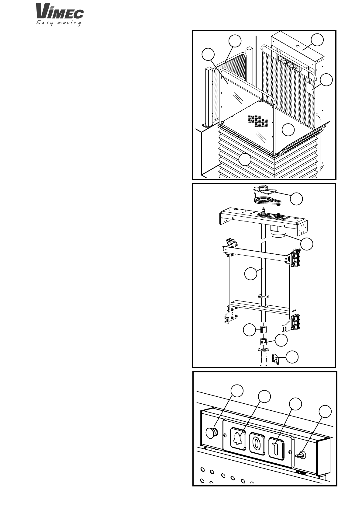
FIG.5
7.3) Ensure that the load is stable.
7.4) Check that there are no foreign bodies underneath
the platform.
7.5) Check that the platform is not working in a
hazard¬ous environment (dust, salt, flammable or
explosive substances).
7.6) Controls at the floors
The control panel on the gate or the rear of the unit
contains the following devices (Fig. 5):
- Control board master key-switch (Fig. 5/a).
- Call button (Fig. 5/b).
7512001

9
a
a
a
7511001
FIG.6
FIG.7
7.8) Use
While the platform lift is in motion the
wheel¬chair’s brakes must be engaged and if it is
electric it must be switched off.
Floor controls:
The controls must be kept pressed throughout the
transit and cut out the lift if released. The floor locks
and the on-board control panel are only operational if
the key has been inserted.
- Insert the key (Fig. 6/a) on the control panel at the
floor and turn it to “1”.
WARNING: Even if the unit is used by more than
one person, only one key must be used.
- Press the call button (Fig. 5/b) and wait for the lock
to open.
If the platform is not at the floor, call it, keep the call
button depressed until the platform reaches the floor,
where it will stop and the gates will open automatically.
If the platform is at the floor, press the but¬ton and the
gates will unlock automatically, granting access to the
platform. The gates are fitted with a sprung closing
system.
On-board controls:
- Insert and turn the key on the on-board control panel.
- Select the floor required.
The up/down button must be held down until the
des¬tination floor is reached. The travel direction can
be changed at any moment. If the button is released,
the platform stops immediately. Once the destination
floor is reached, the platform stops and the gates unlock
automatically.
- Turn the key to 0 (off) and remove it.
- Red emergency stop button.
This button, provided on the control panel on the lift
only, stops the lift immediately regardless of its travel
direction.
To restore the lift to operating mode, turn the stop button
clockwise through 45°.
- Alarm
The alarm buzzer is activated by pressing the ALARM
button on the platform control board.
7.9) Operating Precautions
- The platform must be started and stopped following
the instructions provided in this manual.
- Keep the special keys for opening the gate locks and
main electrical panel in emergencies out of reach of
children or unauthorised persons.
- Always keep the documentation supplied with the unit
(manual, electrical diagrams, warranty) in a safe place.
7512001

10
b
a
a
b
a
c
7511001
Only use the emergency gate opening keys (Fig. 9/a)
when really necessary.
- The platform lift may only be used by a person
stand¬ing or in a wheelchair, with or without attendant.
All other uses are forbidden.
7.10) Recovering the passenger in an emergency
Skill level required TO: Trained operator with
spe¬cific skill.
Recovery of the passenger is necessary in the event of
a lift malfunction or simply a power blackout.
WARNING: Before starting the recovery
proce¬dure, it is COMPULSORY to turn off the power
supply to the lift using the differential security breaker
installed in a box with padlock fixture on the outside of
the panel (to be installed by the customer).
This ensures that the lift cannot be moved accidentally.
Ensure that the gate at the floor is locked.
- Remove the cap that accesses the brake block lever
(Fig. 8/c).
- Remove the cap from the casing to access the hand-
operation mechanism (Fig. 8/a).
- Insert the handwheel provided into the hole in the
casing and fit it on the square drive pin.
- Use the integral lever to keep the motor brake relea-
sed (Fig. 8/b).
- Turn the handwheel to move the platform to the floor.
If the lift is lowered, turning the handwheel requires
less effort.
- At the destination floor, remove the handwheel and
replace the cap.
- To open the gates at the floor by hand, use the trian-
gular key (Fig. 9/a).
FIG.8
FIG.9
7512001

11
a
7511001
WARNING: The lock must only be released with
the key when the platform is at the destina¬tion floor.
Close the gate and call the after-sales service.
8) SAFETY SYSTEMS
a) Safety nut screw
This is a second nut screw which only comes into
op¬eration if the main one is no longer engaged with the
lifting worm screw. If the safety nut screw is engaged,
a electrical failure detection system will prevent the
platform from being used until it is repaired.
b) Locks
Use of the platform is only enabled with the correct lock
status; the unit cannot be used if the gates are open or
the locks have been tampered with.
c) Flap
The platform is fitted with a flap (Fig. 10/a) which has
the dual function of acting as an access ramp at the
floors (when lowered) and holding the wheelchair in
place while the lift is in motion. The flap automatically
moves to the safety position once the platform has risen
a few centimetres above the bottom floor.
The flap only opens at the bottom floor.
8.1) Other Safety Devices
a) Limit switches and limit stops
The limit switches stop the lift automatically in the
embarkation and disembarkation positions when it
reaches the floors.
b) Anti-shearing/anti-crushing guard
The platform is always fitted with a bellows guard on
the open sides.
c) Power Supply
The unit is supplied at 230 V VAC single-phase (50
Hz), while the auxiliary circuit and buzzer are supplied
at 24 VDC.
d) Controls
All the controls are of hold-to-run type (the lift stops as
soon as the finger is removed from the button).
The control boards at the floors are enabled by a
remov¬able key. The platform is not accessible until
the gates have been opened (no-one can use the unit
unless the key is inserted).
FIG.10
e) Operation by hand
The lift can always be raised/lowered by hand to bring
the passenger to the floor in the event of a system failure
or power blackout. (See point 7.10).
f) Emergency stop button
There is a red emergency STOP button on board the
platform. When pressed, the emergency STOP button
cuts out all lift movements and triggers the alarm sy-
stem.
To restore the lift to operating mode, turn the STOP
button clockwise through 45°.
WARNING: Check operation of the emer-
gency STOP button every month. If the STOP button
does not cut out all lift movements, DO NOT USE
the lift!!
Call in an authorised VIMEC technician at once.
g) Movement cut-out in the event of obstacles
The platform is fitted with a sensor which automatically
cuts out downward movement in the event of obstacles
interfering with the moving parts underneath it.
7512001

12
7511001
9) MAINTENANCE
Although the lift has of course undergone rigorous testing, VIMEC advices you to have it inspected regularly by
technicians. In order to ensure that it provides the best service in complete safety, it must be inspected regularly
by our specialist engineers, who will carry out all the operations described below.
9.1) Parts requiring regular inspection
WARNING: Before performing servicing work on the electrical parts, the power supply to the system
must be cut off by means of the “Motive power line” and “Siren” master switch.
Skill level required: SO Skilled operator authorised by VIMEC.
UNIT PARTS TO BE INSPECTED
EVERY
6
MONTS
EVERY
12
MONTS
ON
INSTALLA-
TION
SAFETY DEVICES Check that the sensors stop the lift in the required
posi¬tions at the floors.
Check that the gates are properly interlocked by their
respective locks.
Check that the over-run microswitches are functioning
correctly.
MECHANICAL
LIFTING SYSTEM
COMPONENTS
Check that the lifting structure, bushes, pins, rollers, screw
and nut screw do not show signs of wear, deterioration, or
excessive play on the couplings.
Check that there is no noticeable rust on the load-bearing
structures. Check all components, and particularly the
welded parts, for structural damage.
Check the greasing of the bushing screw and bearing.
Q
MICROSWITCHES Check operation of all safety microswitches.
Check operation of all the controls (control panel – floor
control panel – portable control panel if any).
LOCKS
Check that the locks are functioning correctly. The lift
must only operate with the gates properly closed and
the lock (bolt) shot.
CONTROLS
Check that the lift operates correctly with a load of 1.1
times the permitted payload.
TESTING WITH
LOAD
Check that the device is operating correctly.
ANTI-SHEARING /
ANTI-CRUSHING
BELLOWS GUARD
Check that the devices for hand-operation of the lift are in
good working order.
HAND RAISING /
LOWERING
SYSTEM
Check the tightness of the metal fasteners of the main
components.
BOLTED
CONNECTIONS
Q
QQ
QQ
QQ
QQ
QQ
QQ
Q
QQ
QQ
QQ
QQ
QQ
Check the nut distance.
NUT WEAR Q
7512001

13
x
x
x
x
x
x
x
x
x
x
x
x
x
a
7511001
9.2) Check and replacement of nuts
The two upper and lower nuts coupled to the lead screw
and placed in the column, during the machine operation
the wear is proportionally to the number of cycles and
to the load applied to the platform (people weight).
Therefore, it is necessary to replace the nuts after a
certain number of cycles.
The thread wear of the nuts brings them gradually
closer.
The distance between the two nuts must not be lower
than a certain limit value marked next to the slot (Fig.
11/a).
The initial value – measured during the machine as-
sembly – is also marked next to the slot (Fig. 11/a).
Then it is necessary to measure the distance between
the two nuts with a gauge, and such value must range
between the initial value (higher figure) and the limit
value (lower figure).
If the distance measured with the gauge is lower than
the limit value, the nuts must be replaced.
The following operations must be carried out to measure
the distance between the bushes:
- Remove the column guard.
- Measure the “X” distance between the two nuts (Fig.
13) with a long-clip gauge (see Fig. 12).
- Reassemble the casings and tighten all screws!
Restore the same conditions as before checking.
This check shall be carried out every 6 months
together with all the other periodical maintenance
checks.
FIG.11
FIG.13
FIG.12
7512001

14
7511001
9.3) Troubleshooting
Skill level required: O - trained operator
Problem Possible causes Possible remedies
The platform does not move Emergency STOP pressed Turn the button
in either direction clockwise through 45°
Overload cutout tripped Press the reset button
Differential circuit-breaker Call a VIMEC authorised
tripped technician
Gates and locks Close the gates properly
Safety gear switch Replace drive bushing
The platform does not respond Obstacles underneath the Remove the obstacles
to the “down” command platform
The platform does not respond Gates and locks Close the gates properly
to the “floor call” command
The platform does not respond Platform flap failing to rise
to the “up” command
10) ELECTRICAL WIRING DIAGRAMS
The electrical wiring diagrams are in the folder supplied
with the lift.
11) VIBRATION – AIRBORNE NOISE LEVELS
a) Vibration
The lift causes vibration in the passenger’s body with
the following characteristics:
- low frequency, very low acceleration;
- short exposure cycles for the transported person.
This parameter is therefore insignificant for safety
purposes.
b) Airborne noise: less than 70 dBA
12) GUIDANCE ON DISPOSING OF LIFT PARTS
AND SUBSTANCES
a) Disposing of rubber, plastics and packaging
material.
Place in clean containers and consign to disposal cen-
tres authorised under the relevant regulations.
7512001

15
7511001
GENERAL CONTENTS
1) Lift supply package Page 16
2) Place of installation Page 16
3) Transport Page 16
4) Installation instructions Page 16
5) Final testing Page 28
6) Operating checks and adjustments Page 28
INSTALLATION INSTRUCTIONS
7512001

16
a
a
a
b
c
7511001
1. LIFT SUPPLY PACKAGE
Machine with 1100/1600 mm stroke
- Complete platform
- Preassembled column
- Upper floor gate complete with controls
- Panelling
- Remote call column (OPT)
Machine with stroke greater than 1600 mm
- Complete platform
- Decomposed column
- Upper floor gate complete with controls
- Panelling
- Remote call column (OPT)
2. PLACE OF INSTALLATION
The lift may be installed INDOORS or OUTDOORS.
3. TRANSPORT
3.1) Handling
The lift, disassembled and on a pallet, must be handled
with the aid of suitable lifting equipment with rated load
at least 250 kg (Fig. 1).
Follow the instructions provided in chap. 4
of the assembly manual with regard to the correct
procedures for lifting and positioning the unit.
3.2) Storage
- Store the unit in a dry place
- Protect from dust with PVC sheeting.
FIG.1
FIG.2
4. INSTALLATION INSTRUCTIONS
- Check that the lift and shaft dimensions are as stated
on the installation drawings.
- Check that the mains voltage specifications correspond
to those stated on the lift’s nameplate.
- Check that raceways have been provided for the power
supply cables and that a water drainage pit has been
constructed if necessary.
- Check that the base plinth on which the lift is to rest
is level.
- Place the lift in the intended position, with the distances
from the wall shown in the installation diagrams.
4.1 Wall column assembly for a machine with a
stroke under 1600 mm
- Use the eyebolts to remove the column from the
packaging and from the crate (Fig.1/a) and remove
any front casings (Fig. 1/b-1/c).
250 kg
7512001

17
b
a
a
b
7511001
FIG.3
FIG.4
- Use lifting equipment and slings to move the column
to the wall in a vertical position.
WARNING:
Use a spirit level to check that it is vertical (Fig. 2/a).
- Use plugs to fix the column to the wall by the base
connection (Fig. 3/a) and then to the head connection
or vice versa (Fig. 3/b).
NOTE: Mark on the wall the positions of the holes to
be made before setting the column next to the wall,
thus avoiding dust contamination of the mechanical
organs.
- Using the L brackets supplied (Fig. 4/b) with adjustment
slots, fix the remaining connections (Fig. 4/a).
7512001

18
FIG.6
FIG.7
= =
XX
XX
XX
FIG.8
ab
7511001
4.2 Wall assembly of the column for a machine with
a stroke above 1600 mm
Assemble the connections as follows:
With chemical or mechanical plugs:
- Fix the basic connection to the wall.
- Fix all the other intermediary connections making sure
that they are perfectly plumb and aligned with the first
ones that were mounted (Fig. 5). If anything is out of
plumb, adjust it before tightening the wall plugs - (Fig.
6). Proceed with mounting the guide tracks:
N.B: The “T” tracks have a groove at one end; make
sure that the lower ones appear this way in the upper
part (Fig. 8).
- Mount the guides starting from the lower connection
(Fig. 7/a).
- Mount the remaining guide sections joining the plates
to be bolted - Fig. 8.
- Check the orthogonality of the guides (Fig. 9) before
tightening all the clamps on the connections.
- Also make spot checks of the distance between the
guides measured from the outside, which must be 900
± 0.5 mm.
- Take the head connection to the top of the guides and
use the 4 screws to fix it to the guides (Fig. 7/b).
FIG.5
7512001

19
a
FIG.9
FIG.11
a
b
FIG.10
a
7511001
- Block the head connection in the wall, checking first
if it is perpendicular to the guides. Use the “L” brackets
(Fig. 10/a) for wall fixing and adjust them if necessary.
The head connection is already equipped with a motor
(Fig. 11/a), and electric panel (Fig. 11/b).
7512001

20
FIG.12
FIG.13
a
FIG.14
a
b
a
7511001
- Mount the trolley on the column by raising a guide (Fig.
14/a) in order to insert it easily (Fig. 14/b).
Once the trolley is inserted, reposition the raised guide
and tighten all the bolts.
- Screw the “C” guides to the column (Fig. 13/a).
- Fix the side casings by placing the spacers (Fig. 12/a)
between the casing and high and low connection. Lastly
tighten with the screws provided.
7512001
Table of contents
Other vimec Lifting System manuals
Popular Lifting System manuals by other brands

morse
morse 400A-96SS-117 Operator's manual

REID LIFTING
REID LIFTING PORTA-BASE Assembly & Operation guide

morse
morse 525-N-114 Operator's manual

Terex
Terex Z3413-9461 Service and repair manual

BHM Medical
BHM Medical OXFORD VOYAGER PORTABLE user manual

Chicago Electric
Chicago Electric 47591 Assemble and operating instructions