Vimpex hydrosense HSHWI-100 User manual

INSTALLATION INSTRUCTIONS
Hydrosense Conventional Water Detection System
Document Part No. 3500012 REV03
Page | 1 of 27
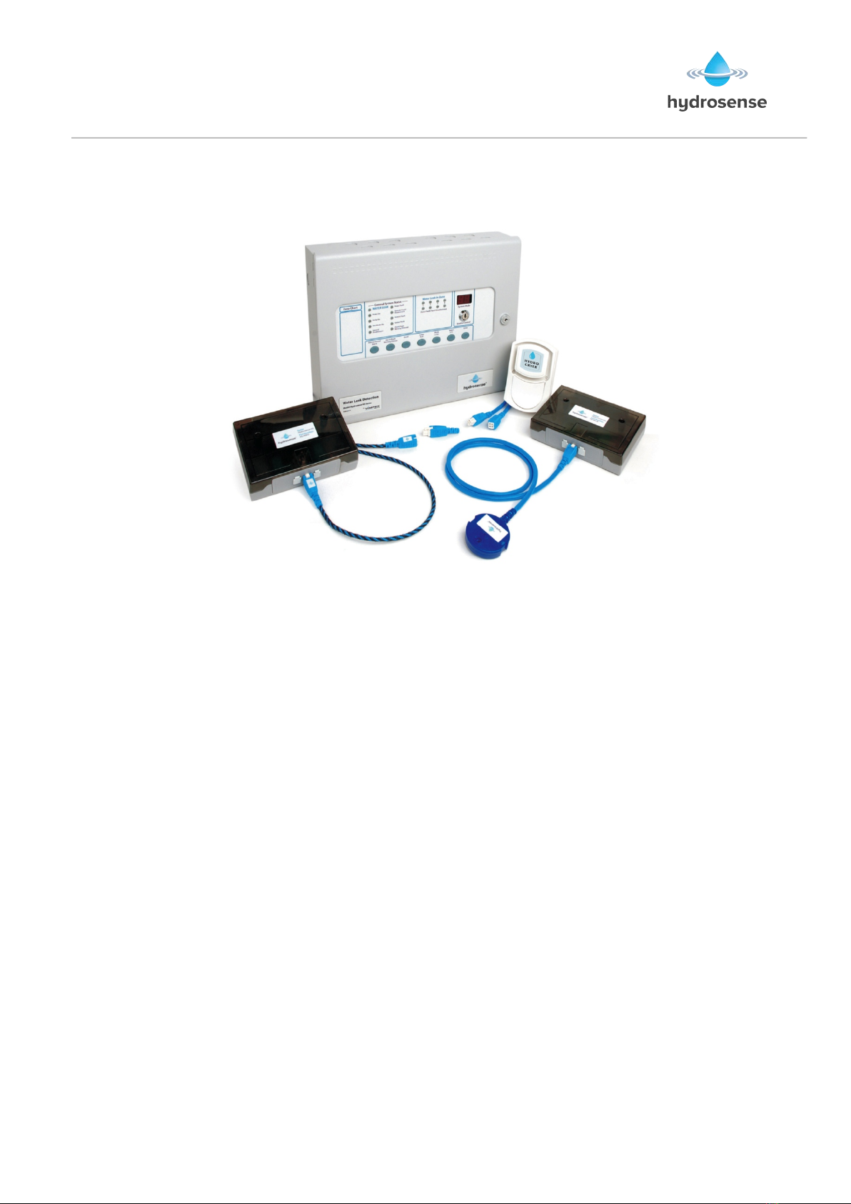
Overview'of'the'Hydrosense'Water'Detection'System'..............................................'2!
Detection'Components'.........................................................................................................'3!
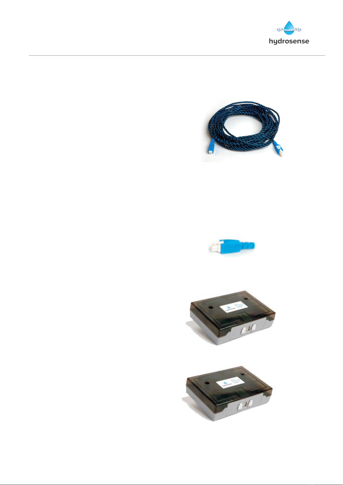
Linear!Detection-!Hydrowire!Cable!.........................................................................................................!3!
Linear!Detection!EOL!.....................................................................................................................................!3!
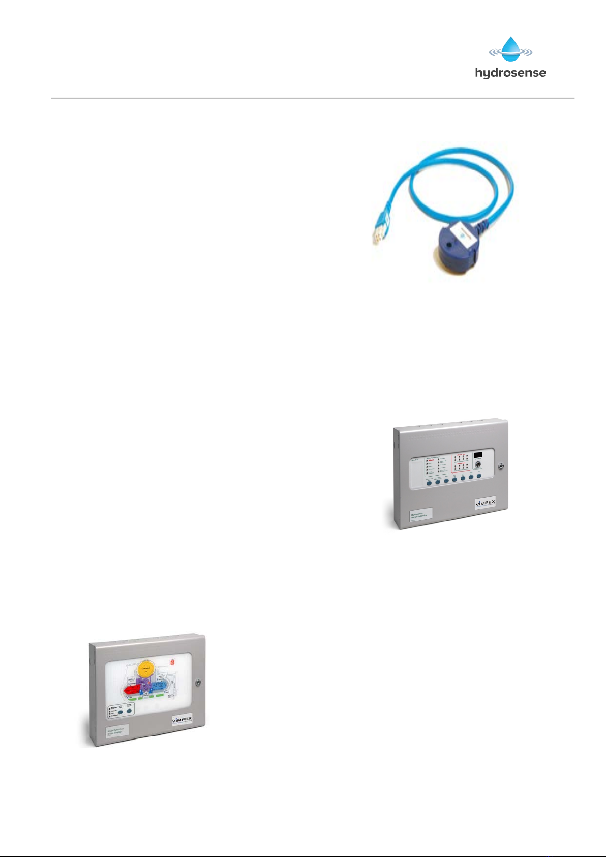
Linear!Detection!Connection!Interface!...................................................................................................!3!
Floor!Probe!Junction!Box!..............................................................................................................................!3!
Point!Detection!Floor!Probe!........................................................................................................................!4!
Control'and'Indicating'Equipment'of'a'Hydrosense'System'...................................'4!
Control!Panel!(2!to!8!Zones)!.......................................................................................................................!4!
Hydrosense!Mimic!Panels!............................................................................................................................!4!
System!components:!.......................................................................................................................................!5!
System!Options!.................................................................................................................................................!5!
Design'&'Planning'..................................................................................................................'5!
Design!Notes!......................................................................................................................................................!5!
Design!Guidelines!............................................................................................................................................!6!
Hydrosense!Floor!Probe:!..............................................................................................................................!6!
Hydrowire!Cable:!.............................................................................................................................................!6!
System!Installation!Notes!.............................................................................................................................!6!
Panel'Installation'...................................................................................................................'7!
Safety!.....................................................................................................................................................................!7!
Panel!Mounting!.................................................................................................................................................!7!
Removing!the!front!facia!...............................................................................................................................!8!
Control!relays!.................................................................................................................................................!12!
Access!level!2!configuration!options!....................................................................................................!13!
Access!level!3!configuration!options!....................................................................................................!14!
Internal!Switches!..........................................................................................................................................!16!
Watchdog!Reset!switch!(W/Dog!Reset)!..............................................................................................!16!
Processor!Reset!.............................................................................................................................................!16!
Internal!Indicators!........................................................................................................................................!17!
Hydrowire'Installation'and'Commissioning'...............................................................'18!
Hydrowire!Installation!HSHWI-100!.....................................................................................................!18!
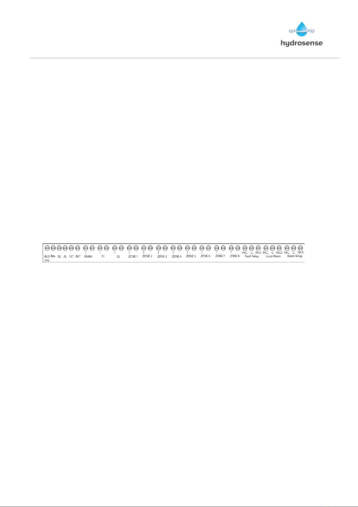
Hydrowire'Wiring'................................................................................................................'19!
Hydrowire!Remote!Lamp!Connection!.................................................................................................!19!
Hydrowire!Commissioning!–!HSHWC-100!........................................................................................!20!
Hydrowire!Layout!.........................................................................................................................................!21!
Floor'Probes'Installation'and'Commissioning'...........................................................'22!
Floor!Probe!Installation!HSFPI!-100!.....................................................................................................!22!
Floor!Probe!Wiring!.......................................................................................................................................!23!
Floor!Probe!Remote!Lamp!Connection!...............................................................................................!23!
Floor!Probe!Testing!.....................................................................................................................................!24!
Probe!Layout!...................................................................................................................................................!25!
Hydrosense'Commissioning'Record'..............................................................................'26!
www.acornfiresecurity.com

INSTALLATION INSTRUCTIONS
Hydrosense Conventional Water Detection System
Document Part No. 3500012 REV03
Page | 2 of 27
Overview of the Hydrosense Water Detection System
The Hydrosense water detection system is designed to detect the intrusion of water in
concealed areas or any place where water penetration must be identified so that corrective
action can be taken immediately.
It will continuously monitor the potential hazards 24 hours a day and has the facility for 24
hours battery standby in the event of power failures.
Any water penetration detected will be signalled to a control panel that can give audible and
visual alarms.
The detection system comprises of three basic components, water detection cable, localised
probes and a control panel.
Water leak detection systems can be divided into two basic categories:
(a) Linear Detection
(b) Point Detection
The Hydrosense supports both types on the system
www.acornfiresecurity.com

INSTALLATION INSTRUCTIONS
Hydrosense Conventional Water Detection System
Document Part No. 3500012 REV03
Page | 3 of 27
Detection Components
Linear Detection- Hydrowire Cable
Where floor areas, ducts and
suspended ceilings need to be
protected this is usually best achieved
by installing lengths of Hydrowire.
Hydrowire is a highly conductive cable
extremely sensitive to moisture. It is
available in 5 metre lengths (HYDW-05)
or 10 metre lengths (HYDW-10).
Each length of Hydrowire is terminated with a male and female 4 way plug to enable them
to be plugged together up to maximum zone length of 50 metres and terminated with an
EOL. It is connected to the panel through the Connection Interface. As soon as the cable
detects moisture this will trigger an alarm. For the cable to measure water on the surface
then it is recommended that the cable is fixed down with Hydrosense fixing clips (HY-
FXSA)
Linear Detection EOL
Each Hydrowire is terminated by an End of
Line Device (HS-HWCI-EOL), which
enables it to be continuously monitored for
defects.
Linear Detection Connection Interface
Each Zone of linear detection cable is
plugged-in to the Connection Interface
module (HS-HWCI) that allows
connection to the control panel using
standard 1.5mm2 2-core cable HYLCB.
Floor Probe Junction Box
Each floor probe is simply plugged-
in to the Junction Box (HS-WLJB)
that allows connection to the control
panel using standard 1.5mm2 2-
core cable HYLCB
www.acornfiresecurity.com

INSTALLATION INSTRUCTIONS
Hydrosense Conventional Water Detection System
Document Part No. 3500012 REV03
Page | 4 of 27
Point Detection Floor Probe
Where a requirement exists for more localised
detection, such as HVAC plant, drip trays, elevator
shafts and storage areas a floor probe (HS-WLDP) can
be installed.
As with the cable the detection of moisture triggers an
alarm and is also monitored by the line fault circuit of
the control panel. Additionally the probe has an LED
indicator on top to identify exactly which probe has
been activated. Up to 20 detectors can be used in each
zone. The probe is simply plugged into the system
using the Junction Box.
Probe is fitted with a 1m cable.
If the distance from the junction box to where the probe needs to be mounted is more than 1m
then additional Extension leads are available in 1m (HY-ZB01), 3m (HY-ZB03) and 10m (HY-
ZB10) lengths.
Control and Indicating Equipment of a Hydrosense System
Control Panel (2 to 8 Zones)
HSCP Series – This panel is available in 2, 4 and 8 zone
configurations. These are fully programmable and allow the
addition of Ancillary PCBs, repeater panels and a Mimic
Display.
Ancillary PCBs provide a means to extend Alarm, Fault,
coincidence and Zonal alarm volt free contacts to locations
remote from the control panel via a 2-core data bus
(RS485).
Hydrosense Mimic Panels
The Hydrosense Mimic Display uses flexible fibre optic guides to illuminate areas on a floor
plan. This provides a clear, geographical indication of the alarm activation enabling a speedy
identification of the source and location of the alarm.
This unique system dispenses completely with wiring and
enables indicators to be moved, removed or added without the
need for any wiring.
It can only be used with the HSCP range of panels.
www.acornfiresecurity.com

INSTALLATION INSTRUCTIONS
Hydrosense Conventional Water Detection System
Document Part No. 3500012 REV03
Page | 5 of 27
System components:
Hydrowire (5 metre Length) HYDW-05
Hydrowire (10 metre Length) HYDW-10
End of Line Plug HS-HWCI-EOL
Hydrowire Connection Box HS-HWCI
Zone Extender (1 metre length) HY-ZB01
Zone Extender (3 metre length) HY-ZB03
Zone Extender (10 metre length) HY-ZB10
Leader Cable (100m lengths) HYLCB
Hydrowire / Leader Cable Fixing Clips HY-FXSA
Batteries Y7-12
System Options
Floor Mounted Probe HS-WLDP
Probe Junction Box HS-WLJB
Remote Indicator Unit HY-WLRI-F
Remote Indicator with Surface Box HY-WLRI-S
Voice Sounder HSVS
White Sounder (Multi Tone) 892A4A0
Banshee Excel Lite - Combined
white sounder and blue strobe 8581800
Design & Planning
Design Notes
!Water finds its own level so careful consideration must be given to slopes and dips in the
area to be protected.
!Can the cable be installed to avoid doorways and traffic.
!Floor probes can be used to protect wells, cavities or hollows.
!Is the site occupied? If so, will the site require just visible alarms or will there be a need
for conventional or voice enhanced sounders?
!Is a remote signalling device required?
!How is the cable to be fixed to the floor? Are other services going to interfere with it?
!Check with the building owner or manager for future plans or designs that may alter the
requirements or siting of the equipment.
!Will the system require expansion? Give consideration to the possible addition of extra
zones.
www.acornfiresecurity.com

INSTALLATION INSTRUCTIONS
Hydrosense Conventional Water Detection System
Document Part No. 3500012 REV03
Page | 6 of 27
!Maximum length of Hydrosense cable should be kept to 50 metres
!Maximum number of detectors per zone should not exceed 20.
!Only one remote indicator to each Hydrowire Connection Interface or Junction Box.
Design Guidelines
Hydrosense Floor Probe:
Maximum recommended coverage: - 20 sq.m per detector
Maximum detectors per zone - 20
Maximum distance between probes for perimeter detection- 3 metres
Sensor height above finished floor - Fixed
Leader cable (HYLCB) - 1.5mm2 2-core cable
Hydrowire Cable:
Maximum recommended length per zone - 50 metres
Recommended pitch between cable for area protection - 2 metres
Minimum bend radius - 150mm
Note: Do not mix probes and Hydrowire on the same zone
System Installation Notes
1. Check design with the kit and components in hand to check that all materials are on site.
Check the BOM.
2. Store Hydrowire lengths carefully in a dry area.
3. Prepare the installation area. Remove any furniture or equipment that may obstruct
installation. Make sure the area is clean and free from debris.
4. Install the Hydrowire in accordance with the installation procedure HSHWI-100
5. Commission the Hydrowire in accordance with the test procedure HSHWC-100
6. Install and test any floor probes in accordance with the appropriate test procedure
HSFPI-100
7. Test the complete system
8. Commission
9. Train the owner / operator
www.acornfiresecurity.com

INSTALLATION INSTRUCTIONS
Hydrosense Conventional Water Detection System
Document Part No. 3500012 REV03
Page | 7 of 27
Panel Installation
Safety
Suppliers of articles for use at work are required under section 6 of the Health and Safety at
Work act 1974 to ensure as reasonably as is practical that the article will be safe and without
risk to health when properly used.
An article is not regarded as properly used if it is used ‘without regard to any relevant
information or advice’ relating to its use made available by the supplier.
This product should be installed, commissioned and maintained by trained service personnel
in accordance with the following:
(i) IEE regulations for electrical equipment in buildings
(ii) Codes of practice
(iii) Statutory requirements
(iv) Any instructions specifically advised by the manufacturer
According to the provisions of the Act you are therefore requested to take such steps as are
necessary to ensure that you make any appropriate information about this product available
to anyone concerned with its use.
The control panel is designed to be operated from either 110V or 230V 50Hz mains supplies
depending upon model and is of class 1 construction. As such it must be connected to a
protective earthing conductor in the fixed wiring of the installation and a readily accessible
double pole disconnect device meeting the requirements of EN60950/IEC950 which
disconnects live and neutral simultaneously shall be incorporated in the fixed wiring. Switch
disconnect devices such as MK Sentry 63A or similar are suitable for this.
Failure to ensure that all conductive accessible parts of this equipment are
adequately bonded to the protective earth will render the equipment unsafe.
The control panel is designed for indoor use only and at temperatures between -50C (+/-
30C) and +400C (+/- 20C) and with a maximum relative humidity of 95%.
The IP rating for the enclosure is IP30.
Operation outside of these limits may render the equipment unsafe.
Panel Mounting
The control panel should be mounted on a dry, flat surface, at eye height to the display and
in a level position such that the enclosure is not distorted.
Screws or bolts of a minimum of 5mm diameter must be used to mount the enclosure in all
three mounting positions.
The panel can be semi or deep recessed using the bezel kit (HYCP-Bezel)
www.acornfiresecurity.com

INSTALLATION INSTRUCTIONS
Hydrosense Conventional Water Detection System
Document Part No. 3500012 REV03
Page | 8 of 27
It should be positioned in an accessible place as agreed with the end user.
Suitable fixings should be used at all fixing points such that the control panel is securely
mounted and is not liable to move once fixed.
The control panel should not be mounted in another enclosure or near sources of excessive
heat.
Cables should be connected using suitable cable glands fitted to the knockouts provided. If
additional cable entry points are required, all swarf and debris caused by drilling of additional
cable entries must be cleared before power is applied to the panel.
Figure 1
G
PE4
E4
5mm DIAMETER SCREWS
FIX TO FLAT SURFACE USING
SUITABLE WALL PLUGS
SIDE VIEW FRONT VIEW
Sufficient room should be available to the left of the panel to allow the front door to be
opened as per diagram below;
Removing the front facia
Open the cabinet with the supplied key, before the fascia can be removed it will be
necessary to unplug the three way terminal block on the left hand side of the PCB. The
fascia of the control panel is held in place by countersunk screws. Undo the two screws and
www.acornfiresecurity.com

INSTALLATION INSTRUCTIONS
Hydrosense Conventional Water Detection System
Document Part No. 3500012 REV03
Page | 9 of 27
lift the fascia gently away from the box towards you. With the fascia removed there is much
more room inside the panel for making off and dressing cables. When cabling work is
complete the fascia can be re-fitted with the two countersunk screws and the red,
green/yellow and black wires re-connected to the three way terminal block
NOTE: It is most important that the polarity of the red and black wires are observed as
wrong connection of these will damage the control panel.
Connecting to the circuit board
All connections for field wiring are to a single row of terminals along the top of the circuit
board. The connections for the power cables are to a pluggable terminal block, which may
be pulled off of the board to remove the plate/PCB assembly. Remove this pluggable
terminal only with mains power off. For Zone connections twin PVC cable with conductors of
.75mm to be used and plastic or metal cable glands can be used for all connections to the
panel.
The resistance of any core of any cable must not exceed 25 ohms.
Wiring should enter the enclosure at the top of the panel using the knockouts provided and
be formed tidily to the appropriate terminals leaving enough wire to ensure that there is no
strain on the PCB. Terminals are capable of accepting wires of up to 2.5mm
Figure 2
Terminal designations
Wiring must not go across the front of the circuit board plate or between the plate and the
circuit board. If cable entries need to be in positions other than at the knockouts provided,
wiring must be fed behind and well away from the surface of the circuit board. The space at
the bottom of the enclosure is occupied by the standby batteries so this must be borne in
mind when considering cable entries.
Remote Inputs
Some functions of the control panel can be controlled externally from the panel if required.
Operation of these inputs should be restricted to access level 2 control. These are
abbreviated at the terminals block as follows:
a) Remote 0V supply - ROV d) Fault – FLT
b) Silence Alarm – SIL e) Reset – RST
c) Sound Alarm – AL
To activate these inputs, the remote 0 Volt (R0V) supply must be connected to the input via
a normally open switch or contact and via a resistance of no greater than 100 ohms.
All of the remote control inputs are non-latching.
www.acornfiresecurity.com

INSTALLATION INSTRUCTIONS
Hydrosense Conventional Water Detection System
Document Part No. 3500012 REV03
Page | 10 of 27
Figure 3
RS 485 Bus
Bus connected devices are connected via a 2 core cable to the terminals marked RS485 +
and – on the main control panel PCB. Up to 14 devices may be connected and each device
has terminals for the incoming cables and outgoing cables. All except the last device
connected to the cable must have the jumper links J2 removed.
Set the devices address using the DIP switch, ensure no two devices share the same
address.
NOTE: Each RS 485 device will need power applied as well as the RS 485 for the device to
operate.
Figure 4
RS 485 Repeater Panels
Connect the RS485 bus and power to each repeater panel. Up to 7 repeater panels may be
connected and each board has terminals for the incoming cables and outgoing cables. All
except the last RS485 device must have the jumper links J2 removed. Turn on the Enable
Control key-switch and set the Write Enable switch to on then briefly press the
PROCESSOR RESET button on the control panel. Wait for a few seconds and the main
panel will show the addresses of the repeaters that were found on the display for instance r1
indicates that a repeater at address 1 has been found.
Turn the write enable switch of, then on again and then press the ENTER button to accept
each repeater that has been found. When all repeaters have been added, set the control
panel Write Enable switch to off.
Press the Watchdog reset switch on the main panel.
www.acornfiresecurity.com

INSTALLATION INSTRUCTIONS
Hydrosense Conventional Water Detection System
Document Part No. 3500012 REV03
Page | 11 of 27
All repeaters are now configured and the control panel will report a fault if any repeaters that
have been accepted become faulty or go off line.
Ancillary Boards
Connect the RS485 bus and power to each Ancillary board. Up to 7 Ancillary boards may be
connected and each board has terminals for the incoming cables and outgoing cables. All
except the last RS485 device must have the jumper links J2 removed.
Set the ancillary board address using the DIP switch (SW2); ensure no two ancillary boards
share the same address.
Apply power to main panel and all ancillary boards then turn on the enable key-switch and
set the write enable slide switch to on, briefly press the PROCESSOR RESET button on the
main panel, wait for a few seconds and the main panel will show the addresses of the
ancillary boards that were found on the display for instance o1 indicates that an ancillary
board at address 1 has been found.
Press the ENTER button to accept each ancillary board that has been found.
The control panel will report a fault if any ancillary boards that have been accepted become
faulty or go off line.
Sounder circuit wiring
All sounders must be of the polarised type. If non-polarised sounders are used the control
panel will permanently show a fault condition.
Sounder circuits are monitored for open and short circuit faults by placing a 10K end of line
monitoring resistor across the last device on the circuit.
Sounder circuits must be wired as a single, radial circuit with no spurs or T junctions to
enable the monitoring circuit to work correctly.
A maximum of 1.6 Amps is available for powering sounders with a maximum load of 0.41
Amps on any one circuit.
Figure 5
www.acornfiresecurity.com

INSTALLATION INSTRUCTIONS
Hydrosense Conventional Water Detection System
Document Part No. 3500012 REV03
Page | 12 of 27
Detection zone wiring
The detection zones provide a nominal 24V DC to power the Hydrosense devices.
The wiring is monitored for open and short circuit fault conditions by removing the 6K8 end
of line monitoring resistors that are supplied fitted to the control panels’ terminals and
placing it in the last Hydrosense Probe junction box or discarded if Hydrowire Connection
Interface is wired to the zone circuit. Detection zone circuits must be wired as a single, radial
circuit with no spurs or T junctions to enable the monitoring circuit to work correctly.
Control relays
Volt free changeover relay contacts are provided for local control and signalling if required.
These contacts are rated for switching signalling circuits only and the maximum 30VDC
1Amp should not be exceeded under any circumstances.
Typically, the Aux 24V output of the control panel is switched through these relays and used
to control other systems.
Fault relay
The fault relay is normally energised and will de-energise upon any fault condition including
total loss of power.
Local Alarm relay
The local fire relay will energise upon activation of a alarm condition on any of the zones or
pressing of the sound alarm button on the front panel. The relay will remain activated until
the alarm is silenced or the panel is reset. This relay will not operate upon activation of the
remote AL input or when an alarm condition is triggered on a zone that is in test mode. This
makes the Local fire relay suitable for inter panel signalling without the panels latching each
other.
Alarm relay
The alarm relay will energise upon activation of an alarm condition on any of the zones. The
relay will remain activated until the control panel is reset. This relay will also operate upon
activation of the remote AL input and the sound alarm button.
www.acornfiresecurity.com

INSTALLATION INSTRUCTIONS
Hydrosense Conventional Water Detection System
Document Part No. 3500012 REV03
Page | 13 of 27
Access level 2 configuration options
Turn enable keyswitch to get to access level 2.
OPERATION
Press Mode button until the required function as detailed below appears in the 7 segment
displays.
For Zonal tests or Disablements, press the Select button to scroll to the required zone
number then press enter. The “select” dot at the bottom of the display will flash to indicate a
test or disablement is active.
For sounder disablements and other functions, press the Select button until the required
function is displayed then press enter to activate that function. The “select” dot will flash to
confirm the setting as above.
[ t1 - 8] Test Zone 1 – 8 (total number of zones will depend upon panel)
[ d1 - 8] Disable Zone 1 – 8 (total number of zones will depend upon panel)
[ db] Disable Sounders
[ Ad] Activate Alarm Delays
[t1 - 8] Test zone
Selecting [t1] through to [t8] puts respective zone into test mode. Zones that are in test
mode shall automatically reset 3 seconds after they have operated. The Test Mode On and
zonal fault/test disablement indicators shall illuminate while any zone is in test mode.
[d1 – 8] Disable zone
Selecting [t1] through to [t8] disables the respective zone. Disabled zones shall not report
alarm or fault conditions. The General Disablement and zonal fault/test disablement
indicators shall illuminate while any zone is disabled.
[db] Disable Sounders
Selecting [db] will disable sounder outputs. The General Disablement and Sounder fault/
Disablement indicators shall illuminate whilst the sounders are disabled.
[Ad] Activate delays
Selecting [Ad] shall make delays configured by access level 3 options C00 to C09 active.
www.acornfiresecurity.com

INSTALLATION INSTRUCTIONS
Hydrosense Conventional Water Detection System
Document Part No. 3500012 REV03
Page | 14 of 27
Access level 3 configuration options
The Hydrosense control panel has many configuration options, which can be set at the time
of commissioning to suit the requirements of the installation. These options are normally set
once and will rarely need to change. The configuration options are only available at access
level 3, which is accessed by operating the Access level 3 switch as shown in Figure 6.
Figure 6
Configuration options are simple to enter using the codes in Table 1 below. When the
control panel is at Access Level 3, the sub-text of the Mode and Select buttons is used to
enter a number using hundreds, tens and units. When the required code number is
displayed (Figure 7), pressing the ENTER button will cause the dot on the units, seven
segment display to flash. This indicates that a configuration option has been set. To review
which configuration options have been set previously, simply scroll through numbers 1 to 99,
A1 to A8 and those with a flashing dot indicate which options have been set.
Figure 7
Access level 3 – Write Enable switch location
www.acornfiresecurity.com

INSTALLATION INSTRUCTIONS
Hydrosense Conventional Water Detection System
Document Part No. 3500012 REV03
Page | 15 of 27
Table 1
Code
FUNCTION
COMMENTS
UXX
CONFIGURATION UPDATE COUNT
Number incremented each time access level 3 config
changed
C00
SOUNDER DELAY TIME = 30 SECONDS
Introduces a time delay before sounders operate.
C01
SOUNDER DELAY TIME = 1 MINUTE
C02
SOUNDER DELAY TIME = 2 MINUTES
C03
SOUNDER DELAY TIME = 3 MINUTES
C04
SOUNDER DELAY TIME = 4 MINUTES
C05
SOUNDER DELAY TIME = 5 MINUTES
C06
SOUNDER DELAY TIME = 6 MINUTES
C07
SOUNDER DELAY TIME = 7 MINUTES
C08
SOUNDER DELAY TIME = 8 MINUTES
C09
SOUNDER DELAY TIME = 9 MINUTES
C10
COMMON ALARM MODE
All sounders operate upon any alarm condition.
C11
2 STAGE MODE
Continuous sounders in alarm zone, others pulsed.
C12
ZONAL MODE
Only sounders connected to zone in alarm operate.
C21
DISABLE BUZZER
Buzzer will not operate in alarm condition.
C22
DISABLE FAULT OUTPUT
Fault relay will only operate under total power loss.
C23
DISABLE EARTH FAULT MONITORING
Earth fault conditions will show a fault condition.
C24
PULSE R0V OUTPUT
0V pulses when alarm triggered.
C27
REMOVE AUX 24V ON SYSTEM RESET
24V supply switches off for 5s when panel reset
C28
INDICATE CALL POINT ACTIVATION
C29
DO NOT RE-SOUND ALARMS FROM ANOTHER ZONE
Silenced sounders do not re-sound with further zone
activations.
C31
ZONE 1 ALARM FROM DETECTOR DELAYED
Sounder outputs will be delayed by time set at options
0-9 when selected zone(s) triggered by Hydrowire or
Floor Probe only.
C32
ZONE 2 ALARM FROM DETECTOR DELAYED
C33
ZONE 3 ALARM FROM DETECTOR DELAYED
C34
ZONE 4 ALARM FROM DETECTOR DELAYED
C35
ZONE 5 ALARM FROM DETECTOR DELAYED
C36
ZONE 6 ALARM FROM DETECTOR DELAYED
C37
ZONE 7 ALARM FROM DETECTOR DELAYED
C38
ZONE 8 ALARM FROM DETECTOR DELAYED
C41
ZONE 1 ALARM FROM CALL POINT DELAYED
Sounder outputs will be delayed by time set at options
0-9 when selected zone(s) triggered by call point only
C42
ZONE 2 ALARM FROM CALL POINT DELAYED
C43
ZONE 3 ALARM FROM CALL POINT DELAYED
C44
ZONE 4 ALARM FROM CALL POINT DELAYED
C45
ZONE 5 ALARM FROM CALL POINT DELAYED
C46
ZONE 6 ALARM FROM CALL POINT DELAYED
C47
ZONE 7 ALARM FROM CALL POINT DELAYED
C48
ZONE 8 ALARM FROM CALL POINT DELAYED
C71
ZONE 1 SHORT CIRCUIT INDICATES ALARM
Changes the trigger threshold of the zone so that the
control panel can be used on older systems that uses
short circuit to trigger the alarm
C72
ZONE 2 SHORT CIRCUIT INDICATES ALARM
C73
ZONE 3 SHORT CIRCUIT INDICATES ALARM
C74
ZONE 4 SHORT CIRCUIT INDICATES ALARM
C75
ZONE 5 SHORT CIRCUIT INDICATES ALARM
C76
ZONE 6 SHORT CIRCUIT INDICATES ALARM
C77
ZONE 7 SHORT CIRCUIT INDICATES ALARM
C78
ZONE 8 SHORT CIRCUIT INDICATES ALARM
C81
ZONE 1 NON-LATCHING
Renders the zone self-resetting so that it can be used
to receive signals from other systems and will reset
when the input is removed.
Note: It can take up to 20 seconds for zone to reset
itself when sounders are operating.
C82
ZONE 2 NON-LATCHING
C83
ZONE 3 NON-LATCHING
C84
ZONE 4 NON-LATCHING
C85
ZONE 5 NON-LATCHING
C86
ZONE 6 NON-LATCHING
C87
ZONE 7 NON-LATCHING
C88
ZONE 8 NON-LATCHING
C91
ZONE 1 NON- SOUNDER MODE
Prevents the zone from operating the two common
sounder outputs.
C92
ZONE 2 NON- SOUNDER MODE
C93
ZONE 3 NON- SOUNDER MODE
www.acornfiresecurity.com

INSTALLATION INSTRUCTIONS
Hydrosense Conventional Water Detection System
Document Part No. 3500012 REV03
Page | 16 of 27
C94
ZONE 4 NON- SOUNDER MODE
C95
ZONE 5 NON- SOUNDER MODE
C96
ZONE 6 NON- SOUNDER MODE
C97
ZONE 7 NON- SOUNDER MODE
C98
ZONE 8 NON- SOUNDER MODE
A1
ZONE 1 30 SECOND INPUT DELAY
Zone needs to be triggered for 30 seconds
continuously before an alarm is generated,
programmable for each zone.
(Prevents spurious alarms)
A2
ZONE 2 30 SECOND INPUT DELAY
A3
ZONE 3 30 SECOND INPUT DELAY
A4
ZONE 4 30 SECOND INPUT DELAY
A5
ZONE 5 30 SECOND INPUT DELAY
A6
ZONE 6 30 SECOND INPUT DELAY
A7
ZONE 7 30 SECOND INPUT DELAY
A8
ZONE 8 30 SECOND INPUT DELAY
AD
ACTIVATE ALARM DELAY
DO NOT set option codes that are not listed in the above table, setting of unlisted options
may have unintended and serious consequences.
Once the required configuration options have been set, the Access level 3 switch must be
returned to its normal position. The General fault indicator will remain lit if the Access level 3
switch is not turned off.
Internal Switches
Watchdog Reset switch (W/Dog Reset)
If for any reason the microprocessor in the control panel fails to carry out its operation
correctly it will attempt to restart itself. This process is called a “watchdog” and the control
panel must record and indicate these events.
If a watchdog event occurs, the control panel will show the FAULT and SYSTEM FAULT
LEDs on the front panel, the CPU fault LED inside the panel and the buzzer will sound. This
fault can only be cleared by pressing the Watchdog Reset button on the PCB inside the
control panel. This is a serious failure and the control panel buzzer will continue to sound
until the watchdog activation is reset.
Processor Reset
Once started, the microprocessor controlling the panel should continue to run the panel
continuously without interruption. If the microprocessor fails to run, it can be reset by
operating the Processor Reset button on the PCB.
This should not normally be necessary but should be done as a matter of course if the
system is behaving abnormally. The system should resume normal operation within a couple
of seconds of pressing the Processor Reset button.
Write Enable
Changes to the configuration as listed in table above require that the changes be stored in
the control panel memory. To enable the memory to be written to it is necessary to operate
the Write Enable slide switch.
www.acornfiresecurity.com

INSTALLATION INSTRUCTIONS
Hydrosense Conventional Water Detection System
Document Part No. 3500012 REV03
Page | 17 of 27
Internal Indicators
Mains fail
Indicates that the 230V AC supply is not present and the system is running on standby
batteries. If there is not a power cut, check the panels mains fuse.
Batt Fail
Indicates that the standby battery has become disconnected or that the charging circuit of
the control panel has failed. Check that both batteries are connected and linked together.
Test battery. Disconnect battery and ensure that 28 Volts can be measured on battery
charger leads.
CPU Fault
Indicates that the central processor unit has failed to correctly execute code and has been
re-started by the system watchdog. The Watchdog Reset switch must be pressed to clear
the CPU fault condition.
Press Watchdog Reset. If system does not return to normal then the panel is probably
damaged and needs the circuit board replacing.
Aux 24V Fault
The Aux 24V and R0V terminals provide a 500 milliamp, 24V DC power supply for power fire
alarm ancillary equipment. This LED indicates that fuse protecting the R0V output has
operated and the rating of this output has been exceeded. The fuse is a self-resetting type
and the supply will resume when the fault condition is removed.
Batt Low
Illuminates when the system is running on batteries and the battery voltage is between 21.5
V and 20.5 V (the minimum battery voltage).
Comms Fault
Indicates that communication has been lost with a repeater panel or Ancillary board. Check
for comms fault at all repeaters and ancillary boards to identify the source of the problem.
Earth Fault
Indicates that part of the system wiring is connected to earth. Remove all system wiring and
re-connect cables one at a time until the earth fault returns. This will indicate which cable the
earth fault is present on.
Sys Fuse Fault
Indicates that the total power rating of the power supply has been exceeded and that the
system fuse has come into operation. Remove and review all loads and re-connect one at a
time until over rated circuit trips fuse to identify troublesome circuit.
S1 and S2 fault
Indicates a short or open circuit on sounder outputs. Remove wiring and refit end of line
resistors. Check sounder circuit wiring.
www.acornfiresecurity.com

INSTALLATION INSTRUCTIONS
Hydrosense Conventional Water Detection System
Document Part No. 3500012 REV03
Page | 18 of 27
Hydrowire Installation and Commissioning
Hydrowire Installation HSHWI-100
Mount the Connection Interface to the area where the start of the Hydrowire is to be
mounted. Wire the Connection Interface back to the Hydrosense Control Panel as shown in
Hydrosense Wiring section.
1. Connect the lengths of Hydrowire to be used in the zone and terminate with an EOL
(HS-HWCI-EOL). Plug the Hydrowire into the Connection Box (HS-HWCI). Power up
Control panel and Check that no fault or alarm is reported on the connected zone.
2. Remove the end of line plug and check that a Fault is reported.
3. Remove power from the Control Panel. Disconnect the Hydrowire and store ready for
installation.
4. Ensure that the installation area is clean and free from water, dust and debris.
5. Plan detection route and mark floor and install clips (HY-FXSA) to the area to be
protected so that the distance between any two Hydrowires is no more than 2 metres.
(For localised protection of sources of potential water leakage, such as air conditioning
and water filled radiators, the distance between Hydrowires may be greater).
6. Plug the Hydrowire cable into the Connection Interface, then lay cable to the first clip
ensuring cable not taught, fit into clips and then push clips down to retain the cable. At
the end of the Hydrowire cable fit the EOL (HS-HWCI-EOL).
7. The Hydrowire cable should be installed so that it remains in contact with the floor for as
much of its length as is possible. Great care must be taken when using other fixing
clips. Although the cable is quite sturdy is can be damaged by crushing or excessive
bending. A bend radius of 150mm is recommended as a minimum.
8. The product label should be left such that it is clearly visible.
Note:Hydrowire should not come into contact with surface temperatures greater than 70oC.
Lengths of greater than 50 metres are not permissible from the Connection Interface, this
distance includes Hydrowire and any Zone Extenders fitted.
Connection Interface
HS-HWCI
End of Line Plug
HS-HWCI-EOL
Hydrowire
HYDW-05
HYDW-10
www.acornfiresecurity.com

INSTALLATION INSTRUCTIONS
Hydrosense Conventional Water Detection System
Document Part No. 3500012 REV03
Page | 19 of 27
Hydrowire Wiring
The HS-HWCI Connection Interface allows the Hydrowire to be plugged in and provides the
installer the option of connecting a Remote Indicator.
The Zone In + and – terminals inside the Connection Interface must be connected via a
1.5mm2 2-core cable (HYLCB) to the Z+ and Z- terminals at the control panel.
Figure 8
The end of line (EOL) resistor at the control panel can be discarded.
It is advisable to leave the lid off the control panel until all testing is complete.
NOTE: The Connection Interfaces cannot be daisy chained together, only one Connection
Interface can be connected per zone.
Hydrowire Remote Lamp Connection
In some installations, particularly in floor voids, it is desirable to identify the area in which
water has been detected with a remote indicator unit (HY-WLRI-F) mounted above the void.
This can be achieved by wiring a HY-WLRI-F remote lamp unit to the –ve and +ve of the RIL
terminals in the HS-HWCI Connection Interface.
NOTE:Only one remote lamp unit can be connected to each Connection Interface.
www.acornfiresecurity.com
This manual suits for next models
2
Table of contents
Other Vimpex Industrial Equipment manuals
Popular Industrial Equipment manuals by other brands

Mitsubishi Electric
Mitsubishi Electric CNC MELDASMAGIC64 Connection manual

SEW-Eurodrive
SEW-Eurodrive MOVITRAC LTP Series operating instructions

ABB
ABB Dodge Quantis BU383 manual

Rottler
Rottler VR9 Operation and maintenance manual

SCHUNK
SCHUNK PGH Series Assembly and operating manual

Rittal
Rittal SV 9677.000 Assembly and operating instructions