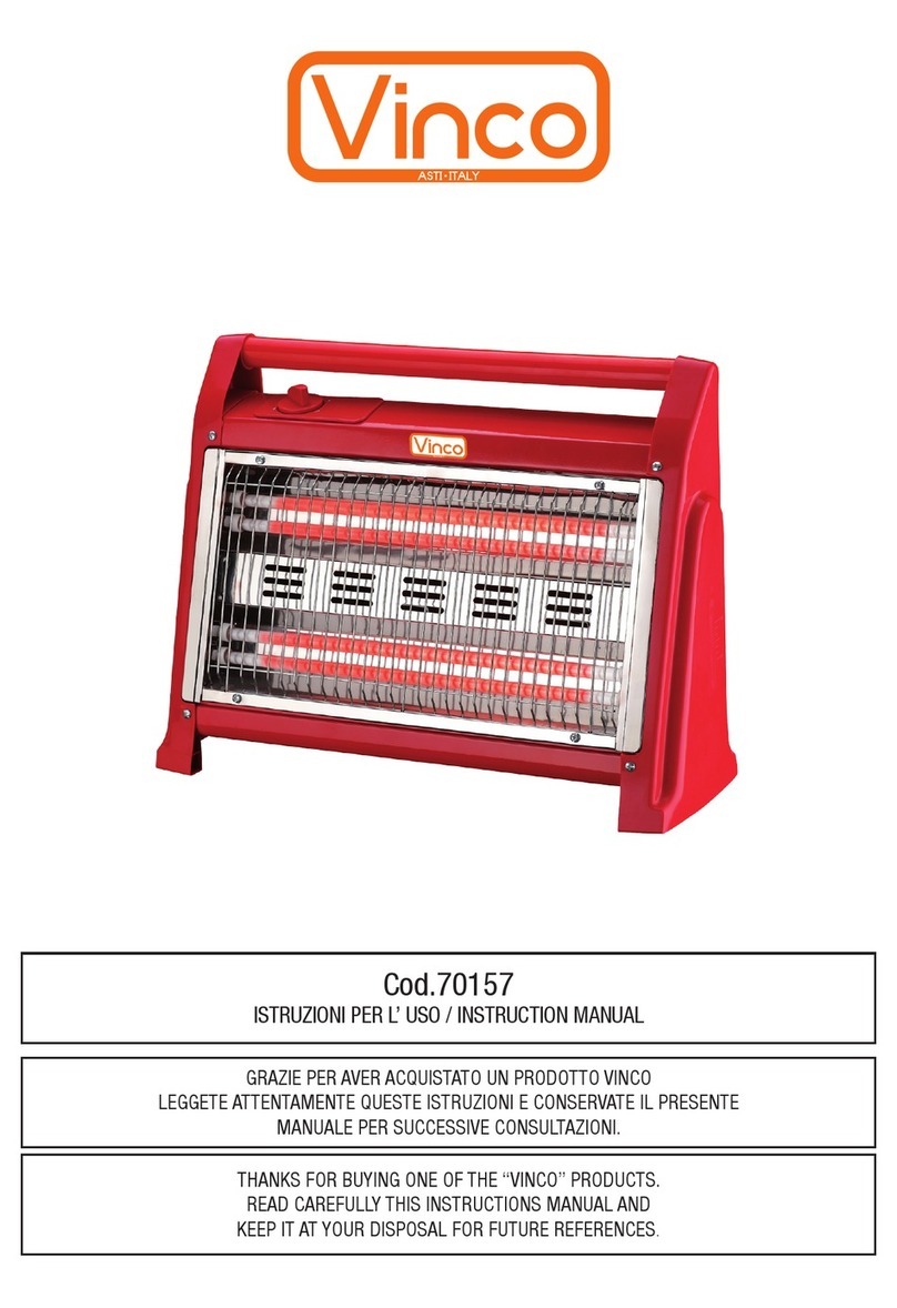
Vinco DL01A User manual

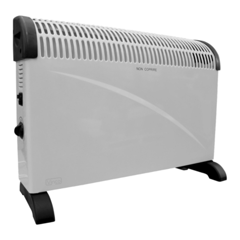
TERMOCONVETTORE/CONVECTOR HEATER
MANUALE D’ISTRUZIONE/INSTRUCTION MANUAL
CODICE: 70503/70504/70505
MODELLO: DL01A - DL01B - CH-Y01FT
GRAZIE PER AVER ACQUISTATO UN PRODOTTO VINCO
LEGGETE ATTENTAMENTE QUESTE ISTRUZIONI E CONSERVATE IL PRESENTE
MANUALE PER SUCCESSIVE CONSULTAZIONI.
THANKS FOR BUYING ONE OF THE “VINCO” PRODUCTS.
READ CAREFULLY THIS INSTRUCTIONS MANUAL AND
KEEP IT AT YOUR DISPOSAL FOR FUTURE REFERENCES.

2
ITALIANO
ATTENZIONE
1.Questo apparecchio dovrà essere collegato ad una presa di corrente approvata dalle norme di
sicurezza degli impianti elettrici di tipo civile. L’impianto elettrico dovrà essere dedicato al voltaggio
nominale dell’apparecchio e dovrà essere dotato di cavo di messa a terra.
2.L’apparecchio dovrà essere utilizzato soltanto per lo scopo cui esso è preposto, e cioè come stufa
per il riscaldamento domestico. Qualsiasi altra applicazione è da considerarsi pericolosa.
3.Il produttore non risponderà di danni provocati dall’uso improprio di questo apparecchio.
4.Posizionare la stufa su una supercie piatta e regolare.
5.Non collocare il termoconvettore in sale da bagno e in prossimità di docce o piscine. Il cavo di
alimentazione non deve venire a contatto con le superci roventi della stufa.
6.Il termoconvettore deve essere posizionato in verticale rispetto al pavimento. Non azionare l’appa
-
recchio nelle vicinanze di tendaggi, materiali combustibili, mobilio, ecc
7.Per evitare il rischio di surriscaldamento, non coprire l’ apparecchio durante l’uso. In caso di danni
o anomalie nel cavo, rivolgersi immediatamente ad un centro di assistenza approvato dal produtto-
re.
8.Non collegare il cavo di alimentazione a prolunghe o spine triple. Non strattonare o danneggiare
in alcun modo il cavo di alimentazione. Prima di qualsiasi operazione di manutenzione, scollegare
la spina dalla presa di corrente elettrica.
MODALITA’ D’USO
Quando il termoconvettore viene messo in funzione per la prima volta oppure dopo un lungo tempo
di inutilizzo potrebbe generare odori dovuti al riscaldamento dei componenti. Tale fenomeno scom-
parirà dopo qualche tempo di utilizzo
Posizionare in luogo adatto tenuto conto delle precedenti istruzioni.
Inserire il cavo di alimentazione nella presa di corrente. Vericare che non siano collegati altri appa
-
recchi alla stessa presa di corrente.
Girare l’interruttore termostatico in senso orario no alla massima temperatura.
Agire sull’interruttore situato sul pannello laterale e selezionare la capacità riscaldante (750 / 1250 /
2000 W).
Girare l’interruttore termostatico in senso antiorario no al “click” di disinserimento e posizionarlo
nuovamente al di sopra del “click” o alla temperatura di riscaldamento desiderata. A questo punto
il termoconvettore rimarrà in funzione no al raggiungimento della temperatura ambiente program-
mata dal termostato. Scegliere fra le tre possibilità riscaldanti a seconda della velocità di riscalda-
mento desiderata.
SUPPLEMENTO DI ISTRUZIONI PER IL COD.70504 e 70505
Questi modelli sono dotati di ventilazione forzata. Il ventilatore viene comandato da un interruttore
posto sul pannello a lato del convettore. L’interruttore di comando è riconoscibile dal simbolo del
ventilatore (vedi gura “Pannello di controllo”). Il ventilatore viene azionato quando il termostato e gli
interruttori di comando degli elementi riscaldanti sono in posizione “ON” in modo da mandare aria
calda nell’ambiente. Durante la stagione estiva il ventilatore può essere utilizzato per mandare aria
fresca nell’ambiente posizionando gli interruttori di comando degli elementi riscaldanti in posizione
“OFF”.
SUPPLEMENTO DI ISTRUZIONI PER IL MODELLO COD: 70505
Questo modello è dotato della funzione di programmazione di funzionamento a mezzo di un
“TIMER” posto sul pannello laterale del convettore. Il “TIMER” può essere programmato per 24
ore, è dotato di 96 segmenti posti sulla circonferenza esterna e ogni segmento corrisponde ad una
frazione di tempo di 15 minuti ciascuno. Utilizzando il “TIMER” è possibile preselezionare la durata

3
ITALIANO
del funzionamento del convettore nell’arco delle 24 ore.
FUNZIONAMENTO DEL TIMER
Nella parte centrale del “TIMER” è posto un interruttore a scorrimento a 3 posizioni.
Con l’interruttore nella posizione centrale con il simbolo dell’orologio il convettore verrà messo in
funzione o si spegnerà a seconda della programmazione dei segmenti esterni.(vedi di seguito)
Con l’interruttore nella posizione con il simbolo “I”, il “TIMER” continua a funzionare e continua ad
arrivare corrente al convettore per permettere il funzionamento per il tempo desiderato.
Con l’interruttore nella posizione “0”, il “TIMER” continua a funzionare ma non arriva corrente al
convettore.
PROGRAMMAZIONE DEL TEMPO DI FUNZIONAMENTO
Assicurarsi che l’interruttore a scorrimento posto sul “TIMER” sia nella posizione centrale in corri-
spondenza del simbolo dell’orologio.
Posizionare l’anello rotante del “TIMER” sul numero (da 0 a 24) corrispondente all’ora attuale facen
-
do coincidere la “FRECCIA INDICATRICE” con in numero stesso.
Selezionare l’ora di partenza del funzionamento del convettore estraendo il segmento della circon-
ferenza esterna corrispondente all’ora di avvio desiderata ed un secondo segmento per program-
mare lo spegnimento. Questa programmazione permette di far funzionare il convettore nei giorni
successivi negli stessi periodi di tempi selezionati. Afnché questo avvenga, il convettore deve
sempre essere collegato alla presa di corrente ed il termostato e gli interruttori di comando delle
unità riscaldanti in posizione “ON”. Se viene richiesto un utilizzo continuo del convettore portare
l’interruttore scorrevole del “TIMER” in posizione “I”. Se si vuole ritornare alla funzione di program-
mazione del tempo di funzionamento portare l’interruttore scorrevole sulla posizione con il simbolo
dell’orologio.
MONTAGGIO A MURO
Nell’imballo del termoconvettore vi sono tasselli e supporti da utilizzare per il ssaggio a muro.
Qualora si desideri ssare il convettore al muro non devono essere montati i piedi di sostegno e
devono essere osservate alcune prescrizioni.
•Non montare di fronte a prese di corrente.
•Non montare in prossimità di tendaggi, di tappeti o di moquettes.
•Vericare che il usso d’aria calda non sia ostruito da tessuti o oggetti vari.
•Non montare in vani molto piccoli che non permettono una buona circolazione d’aria.
•Praticare due fori nel muro diametro 8mm ad una altezza minima di 400mm dal pavimento e con
•un interasse di 486 mm. Utilizzare i tasselli forniti per ssare il convettore al muro e le staffe in
•plastica per sostenere e per distanziare il convettore dal muro.
DIPOSITIVO DI SICUREZZA
Questo apparecchio è dotato di un dispositivo di sicurezza che disabilita l’alimentazione della stufa
nel caso essa si ribalti accidentalmente. Il dispositivo si trova al di sotto della base dell’apparecchio.
MANUTENZIONE
1.Questo apparecchio richiede esclusivamente la pulizia delle supercie esterna.
2.Dopo l’uso e prima della pulizia, scollegare la spina dalla presa e attendere che la stufa si raffred
-
di.
3.Per la pulizia delle superci esterne, utilizzare esclusivamente un panno inumidito. Non usare
solventi.

4
ENGLISH
CAUTION
1.Remove the packing and make sure that the appliance is intact .In case of doubt do not use the
appliance and contact our after-sales service. Do not leave packaging materials like bags and staples
within reach of children.
2.Before switching on appliance check if the electrical voltage and frequency of the circuit correspond
to those indicated on the appliance.
3.The appliance has to be connected to a circuit according to the rules in force concerning the civil
plant .The plant has to be related to the nominal power of the appliance and has to be provided with
an earth-wire.
4.The manufacturer is not responsible for any eventual damages caused by improper or faulty use.
5.The use of every electrical appliance calls for the awareness of some basic rules such as
6.When the appliance is not in use switch it off and unplug it. Make harmless the parts of the appli-
ance, which could be handled hazardously by children for playing.
7.Do not use this heater in the immediate surroundings of both, a shower or a swimming pool.
8.Do not put the cable on the appliance when it is still warm.
9.Do not use the appliance near liquids or inammable matters.
10.Do not locate the heater below a socket outlet.
11.Do not use this heater with a programmer, timer or any other device that switches the heater on
automatically, since a re risk exists if heater is covered or displaced.
12.Do not cover the appliance when it is running to avoid overheating risks.
13.In case the power cord is damaged send it to the nearest after-sale service recommended by the
manufacturer for the replacement.
14.Children .old people and disabled people are not often aware of the dangers. Which can derive
from improper use of the appliance .The appliance should never be used without an adult supervision.
15.Do not connect the appliance to extension cords or multiple outlets.
16.Do not damage and do not kink the power cord. Before cleaning the appliance or carrying out any
maintenance switch off the whole system.
17.If the appliance is out of work switch it off without tampering it .If any repair is required please
contact only the after–sale centers approved by the manufacturer and ask for original spare parts.
Otherwise safety of the appliance can be compromised.
ASSEMBLY OF THE HEATER
Before using the heater, the feet (supplied separately in the carton), must be tted to the unit. These
are to be attached to the base of the heater using the 4 self-tapping screws provided, taking care to
ensure that they are located correctly in the bottom ends of the heater side moldings
OPERATION
NOTE:- It is normal when the heaters are turned on for the rst time or when
they are turned on after having not been used for a long period of time the
heaters may emit some smell and fumes. This will disappear when the heater
has been on a short while.
Convector heater with thermostat 70503
Choose a suitable location for the heater, taking into account the safety
instructions above.
Insert the plug of the heater into a suitable socket.
Turn the thermostat knob fully in a clockwise direction to the maximum setting.
Turn on the heating elements by means of the rocker switches on the side panel. When the heating
elements are on the switches will illuminate. For maximum heat output both switches should be on.
When the desired room temperature has been reached, the thermostat knob should be turned slowly
anti-clockwise until the thermostat is heard to click off and the lights on the element switches are seen
to go out. After this the heater will keep the air temperature in the room at the set temperature by
switching on and off automatically.
In it’s minimum (fully anti-clockwise) position, the thermostat provides a frost guard position. In this

5
ENGLISH
position (depending on the size of the room) the heater will maintain the temperature above freezing.
CONVECTOR HEATER WITH THERMOSTAT AND FAN 70504
All the above instructions for model CH-01 STAND (above) also apply to model CH-01 TURBO.
Model CH-01 TURBO also incorporates an internal fan, which can be switched on independently of
the heating elements.
Fan Operation: -This is operated by means of the switch with the fan symbol along side it. The fan will
only operate with the thermostat in the “on” position and can be used when the heating elements are
“on” to blow warm air into the room. In warm conditions the fan can be used with the heating elements
“off” to blow cool air into the room.
CONVECTOR HEATER WITH THERMOSTAT AND TIMER 70505
All the above instructions for model CH-01 STAND (above) also apply to model CH-01 TIMER.
This model is also tted with a 24hr timer which has 96 segments around its circumference, each seg-
ment being equivalent to 15 minutes of time. With the aid of this timer it is possible to preset the time
and duration of the period(s) that it is desired the heater will operate, in any 24hr period.
Timer Operation
The centre of the timer has a 3 position slide switch.
In the central position (denoted by the clock symbol) the timer will switch the heater on and off at times
set by the segments, (see setting the timer, below).
The position denoted by the “I”, is a timer override position. The timer will continue to run but power
will be fed continuously to the heater. This enables the heater to be on all the time if required.
In the position denoted by the “O”, the timer continues to run but no power is fed to the heater.
Setting the Timer
Ensure the slide switch on the timer is at the mid position next to the clock symbol.
Rotate the outer ring of the timer in a clockwise direction until the current time is lined up with the ar-
row pointer, i.e. if the time the timer is being set is 8 pm, rotate the outer ring until the number 20 is in
line with the arrow pointer.
Set the time the heater is required to run by pulling the segments around the outer ring forward ap-
propriate to the running period(s) required.
When set, the heater will operate each day during the times programmed. Note, the heater must
always be plugged into a power socket, the element switches must be in the on position and the ther-
mostat must be suitably set to ensure the heater will come on.
If the heater is required to run continuously the slide switch on the timer should be set to the “I” posi-
tion.
If it is subsequently required to revert back to timer operation, the slide switch on the timer should be
set to the central (clock) position.
Note:- When using in timer mode, due consideration should be given to the fact that the heater may
come on whilst unattended.
WALL MOUNTING
The heater is supplied with 4 off each xing brackets, screws and plastic wall plugs to enable it to be
mounted onto a wall if required.
If it is decided to mount the heater on the wall, the feet should not be tted. The position must be
chosen carefully. It must not be in front of or below a power socket. It must not be below a shelf,
curtains or any other obstruction. Also refer to the safety instructions overleaf.
Having decided on the location of the heater it is necessary to drill 2 xing holes 8mm diameter by
43mm deep at 486mm centres on a horizontal line at a minimum height of 400mm from the oor. Al-
lowance must be made for any oor coverings, carpet etc and if any skirting boards are present, the
xing holes must be a minimum of 400mm above the top edge of the skirting board. Using the plastic
plugs and xing screws provided, attach 2 of the xing brackets to the wall. The other pair of xing
brackets must be attached to the base of the heater using the feet retaining screws so that the brack-
ets project out at the rear of the heater and space the bottom edge away from the wall.
If required, these brackets may also be secured to the wall using the remaining xing screws and
plastic wall plugs. If this option is chosen it is suggested that the heater is hung on the upper brackets

6
ENGLISH
and the hole positions for the lower brackets is then marked on the wall, prior to drilling the holes
for attachment purposes.
SAFETY DEVICE
This appliance is provided with one safety device, the safety device disconnects the appliance
when the heater is tilted or when is tipped by means of a switch situated in the lower part of the
heater.
MAINTENANCE
The appliance needs only an external regular cleaning.
After use and before cleaning always unplug the appliance and wait till the item is cool
Clean the grilles from dust.
Do not clean the painted parts with emery our or solvents and use only a moistened cloth.

IT Dichiarazione di conformità CE SK Prehláŝenie o zhodě ES BA/HR EG – izjava o konformnosti
FR Declaration de conformité CE PL Deklaracja zgodności WE RO Declaraţie de conformitate CE
GB EC delaration of conformity SI ES izjava o skladnosti DE EG - Konformitätseklärung
CZ Prohláŝeni o shodě EU HU CE-megfelőségi nyilatkozat
DE Produkttyp GB Product PL Produktu BA/HR Proizvoda
70503 / DL01A
70504 / DL01B
70505 / CH-Y01FT
IT Prodotto CZ Produktu SI Proizvoda RO Produsului
FR Produit SK Produktu HU Termek típusa
IT Direttive CE SK Aplikovatel’né smernice EU BA/HA EG – smjernice
FR Directives CE applicables PL Dyrektywy WE RO Directive UE applicabile
GB Applicable EC directives SI Uporabljene ES smernice DE Anwendbare EG-Richtlinien
CZ Směrnice EU
HU
EU Műszaki Irányelvek
2006/95/EC (LVD) - 2004/108/EC (EMC) - 2002/95/EC (RoHS) - 2002/96/EC (Raee)
IT Norme armonizzate applicat SK Použité harmonizované normy
EN 12601:2001
EN 55012/A1:2005
EN60335-2-2-2003
EN6223:2008
EN60335:1:2002
FR Normes armonisées applicable PL Zastosowano zharmonizowane normy
GB Applicable harmonized standards SI Uporabljani usklajeni normativi
CZ Aplikované harmonizačni normy
HU
Alkalmazott harmonizált szabványok
DE Angwandte harmonisierte normen
BA
HA
Primijenjene harmonizirajuće norme
RO Norme armonizzate aplicabile
VINCO s.r.l. - C.so Aleri n°177 - 14100 Asti - Italia
DE Hiermiterklärenwir,dassdernachfolgendbeschriebeneArtikelaufgrundseinerKonzipierungundBauartsowie
indervonVincoSRLinVerkehrgebrachtenAusführungdeneinschlägigengrundlegendenSicherheits-undGesundheitsanforde-
rungenderEG-Richtlinienentspricht.
IT Conlapresentedichiariamochel’articolodiseguitodescritto,inbaseallasuaconcezioneecostruzioneedalla
messaincircolazionedapartedellaVincoSRLèconformeairequisitifondamentalidisicurezzaesalutedelledirettiveCE.
FR Aveclaprésentenousdeclaronsquel’articledécritci-aprèsrepondenmatièredeconceptionetdeconstruction
ainsiquedanssonmodèlecommercialiséparlaVincoSRLauxesigencesfondamentalesdesécuritéetsanitairesetauxdirectives
communitairesapplicable.
GB Weherewithdeclarethatthefollowingproductcomplieswiththeappropriatebasicsafetyandhealthrequirements
oftheECdirectivesbasedonitsdesignandtype,asbroughtintocirculationbyVincoSRL.
CZ Timtoprohlašujemeženásledovnépopsanezbožísvoukoncepciakonstrukcirovněžiprovedením,jenžbylodánodo
prodejespolečnostiVincoSRL,odpovidápřislušnýmzákladnímbezpečnostnímazdravotnímpožadavkůmsměrnicEU.
PL Niniejszymdeklarujemiiżniżejokreślonyartykul,wformiewprowadzonejnarynekprzezVincoSRL,spelniazewzględuna
projectIconstrucjępodstawowewymaganiabezpieczeństwapracyorazochronyzdrowianarzucaneprzezdyrektywyWE.
SK Týmtoprehlasujemeženasledovnepopisovanýtovarnazákladesvojhonávrhuakonštruckcie,akoajprevedenia
uvedenéhospoločnost’ouVincoSRLdoprevádzky,inzdravstvenimzahtevam,kisovskladnostizEUsmernicami.
SI StemizjavljamomidajeopisaniproizvodnaosnovinjegovenasnoveinvrstekonstrukcijekottudipriVincoSRLv
prodajospuščenaizvebdaodgovarjatemelijnimvarnostniminzdravstvenimzahtevam,kisovskladnostizEUsmernicami.
HU
EzennelnyilatkozunkhogyakövetkezőkbenleírtárucikkkoncepciójábanéskivitelimódjábanvaliantazVinco
SRLáltalforgalombahozottkivitelébenmegfelelazEUrávonatkozóalapvetőbiztonsági-esegészségvédelmielőirásainak.
BA/HR
Ovimizjavljujemodauslijedećemopisaniproizvodnaosnovunjegovogkoncipiranjainačinagradnjekaoi
izlaganjaizdanogodVincoSRLodgovarajasmin,osnovnimsigurnosnimizdravstvenimzahtjevimaEGsmjernica.
RO Noideclaramdeproprieraspunderecaarticoluldescrismaijos,pebazaconcepţieişitipuluisauconstructivsale,
precumşialexecuţiilorpuseîncirculaţiedeVincoSRL,seconformeazacerinţelorpentrusecuritateamunciişisanataţiiale
directivelorUEînmaterie.
Astili,25giugno2015
L’Amministratore
LidioConti
7
ITALIANO

8
ITALIANO


RoHS
MADE IN CHINA
Importato da Vinco S.r.l.
Corso Aleri, 177 – 14100 Asti (AT) ITALY
TEL.0141.351284
CENTRO RICAMBI E ASSISTENZA:
Viale Giordana, 7/bis
10024 Moncalieri (TO) - ITALIA
e-mail: [email protected]
This manual suits for next models
5
Table of contents
Languages:
Other Vinco Heater manuals
Popular Heater manuals by other brands

DEVOLA
DEVOLA Platinum DVSH3000WHS instruction manual

Winterwarm
Winterwarm DXA75 installation manual

Perel
Perel EHD1 user manual

Stover
Stover SRE 712 datasheet

Joannes
Joannes VENUS BA MS 24- 34 Instructions for use, installation and maintenance

S&P
S&P HEC-3000 Installation manual and operating instructions