Vira ViraVent SV-F Series User manual

USER MANUAL
ENGLISH LANGUAGE

2 English User Manuel - 1.0
TABLE OF CONTENTS
1. Preface 2
2. Introduction 3
3. Technical Specifications 5
4. Safety 6
5. Installation And Commissioning 6
6. Preventive Maintenance 8
7. Installations 9
8. Product Dimensions 11
9. Hydraulic Balance Tank 14
10. Pressure Drop 15
1. PREFACE
1.1. About The Device
This Viratech product improves the quality of
your complete installation.
• For an overview of the product, refer to
section 2.1.
• For the intended use, refer to section 2.3.
is Vira product is designed and manufactured
according to the Sound Engineering Practice
as stated in the Pressure Equipment Directive
(2014/68/EU).
is manual applies to product types starting
with the codes shown below:
SV
Code pt
SB ViraBalance
... Co
F
K
V
Wn
M
V
F langed
Magnet
Co e
HH�gh-Flow
TDemountable
• 0
•5
•0
•0
•5
•0
•0
•0
•0
1.2. Symbols
Throughout the instructions the following symbols
are used:
Note
Warn�ng (r�sk of �njury) or caut�on (r�sk of
damage)
R�sk of burns

3EnglishUser Manuel - 1.0
1
2
3
4
*
*
*
5
a
h
gi
e
bcd
f
1. Automatic air vent / manual air vent
2. Lifting lugs
3. Scum valve
a. Flange
b. Welded ends
c. Victaulic connection
d. Fixed bottom
e. Demountable bottom
2.2. Overview Of The Product Variations
4. Main body
5. Safety plug
* Product variation. Refer to section 2.2.
f. Drain valve
g. Rotatable dry pocket (with magnet and drain valve)
h. Separated vertical connection
i. Unified vertical connection
2. INTRODUCTION
2.1. Overview Of The Unit

4 English User Manuel - 1.0
2.3. Intended Use
• ViraVent: the unit (fully) automatically
removes all available bubbles and microbubbles
from the water and water/glycol mixtures.
• ViraClean: the unit (fully) automatically
removes (magnetic) dirt that has a higher
specific weight than the system uid from the
water and water/glycol mixtures.
• ViraPlus: the unit (fully) automatically
removes air, gasses, and (magnetic) dirt from
water and water/glycol mixtures.
• ViraFix: the unit hydraulically balances
and separates the primary and secondary ow in
the installation, in combination with the (fully)
automatic removal of air, gasses, and (magnetic)
dirt from water and water/glycol mixtures.
• ViraBalance : the unit hydraulically
balance the primary and secondary ow in the
installation.
2.4. Operating Conditions
The unit is suitable for use in systems filled
with water or mixtures of water and glycol up to
40%. The unit can be used in combination with
chemicals / inhibitors approved according to
local directives. Please check that the materials
in the unit are compatible with the materials and
uid used in your system. For more information
contact your supplier. Operation in combination
with other uids may result in irreparable
damage.
2.5. Scope Of Delivery
• 1x Unit
• 1x Quick reference guide*
• 1x Drain valve for the dry pocket
* Each Quick reference guide has a QR-scan code
with a direct link to this user manual.
2.6. Identification Sticker
Example:
Example:
A. Company Logo
B. Article Number
C. Fluid
D. Working Temperature
E. Working Pressure
F. Connection
G. Serial Number
H. Design & Manufacturing
I. Barcode Number
J. Purjor Angle
K. International Standard
L. Square Code
M. Website
A
B
J
K
L
M
C
D
E
F
G
H
I
WARNING
The unit is not suitable for demineralised water,
and cannot be used for drinking water, and
dangerous or ammable substances.
The unit should be used within the limits of the
technical specifications as given in chapter 3. In
case of doubt, always contact the supplier.
The unit is not suited for outdoor use.

5EnglishUser Manuel - 1.0
3. TECHNICAL SPECIFICATIONS
3.1. Operating Characteristics
3.2. Quality Control Specifications
NOTE
These are the specifications of the quality control at Vira.
3.2.1. Leak Test Specifications
3.2.2. Functional Test Of The Automatic Air Vent
3.2.3. Standards
Item All types
Work�ng pressure [bar-g] 0 - 10
Work�ng temperature [°C] 0 - 110
Nom�nal flow veloc�ty [m/s] 1.5
Max�mum flow veloc�ty of h�gh-
flow speed un�ts [m/s]
3.0
Flange type of flanged un�ts PN16 (DIN2633) (EN1092)
Item All types
Test pressure [bar-g] >15
Water & A�r
Test med�um
240Test t�me [sec.]
Approval criterion No leakage
Item
Valve opening test Full bore venting
All types (except for SD - SB ...)
Valve closing test Pos�t�ve valve closure
Item All types
ev�tcer�Dtnemp�uqEerusserPno�tcurtsnoC 2014/68/EU - Sound Eng�neer�ng Pract�ce
Qual�ty, safety and env�ronmental
aspects
NEN-EN-ISO 9001
NEN-EN-ISO 14001
NEN-EN-ISO 45001
4. SAFETY
4.1. Safety Instructions
WARNING
• Installation and maintenance may only be carried out by a qualified installer.
• When working on the unit, always ensure there is no pressure in the unit, let it cool down and remove
the water from the unit. This is not applicable when draining dirt from the unit.

6 English User Manuel - 1.0
5.2. Install the unit
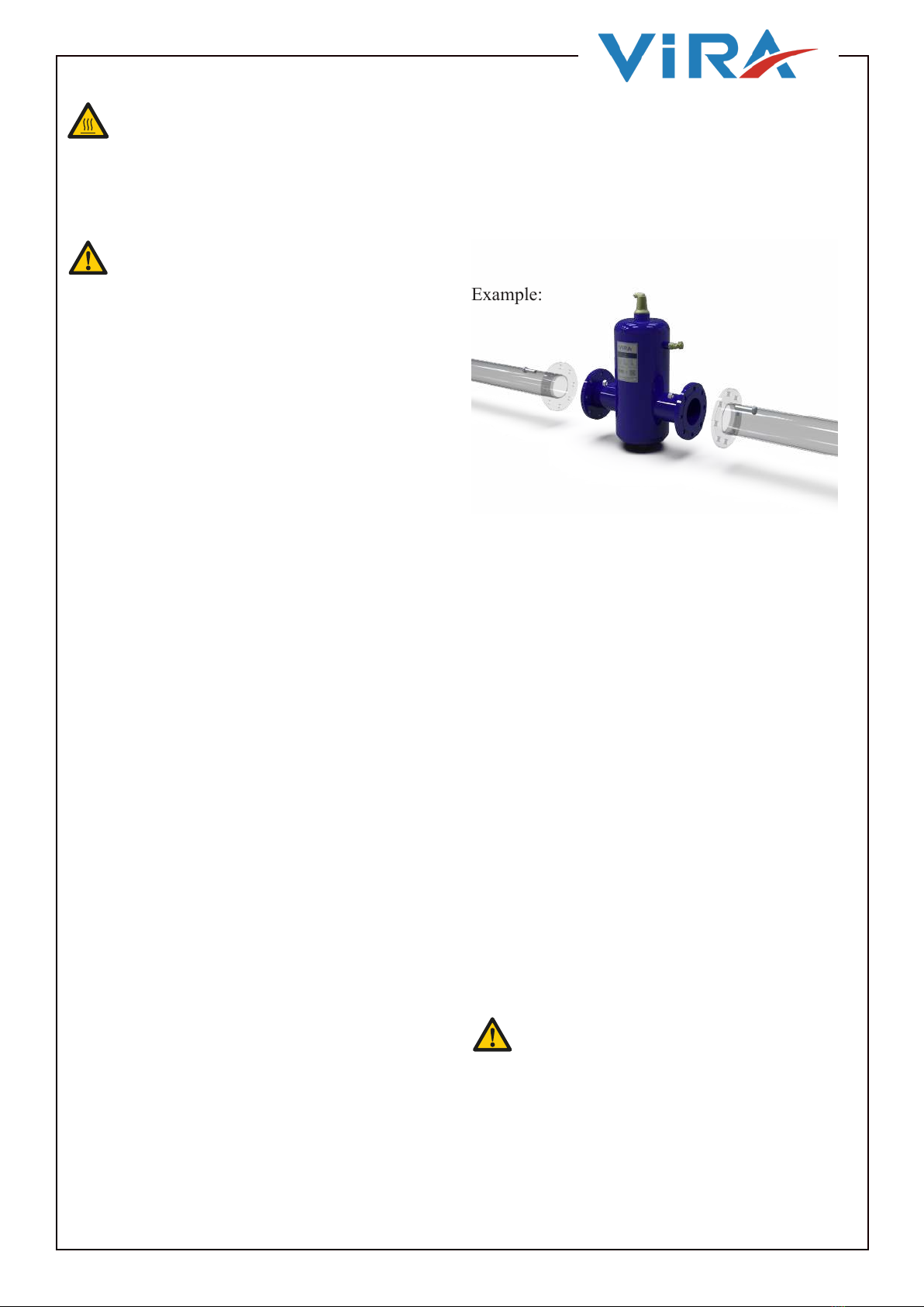
5.2.1. Mount The Unit
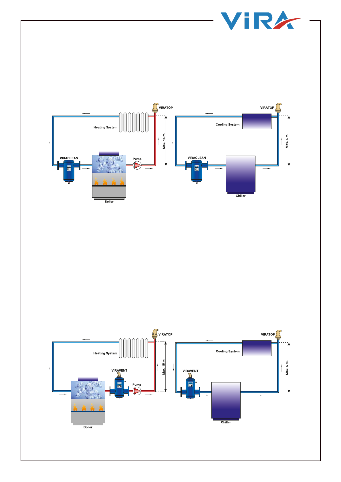
Example:
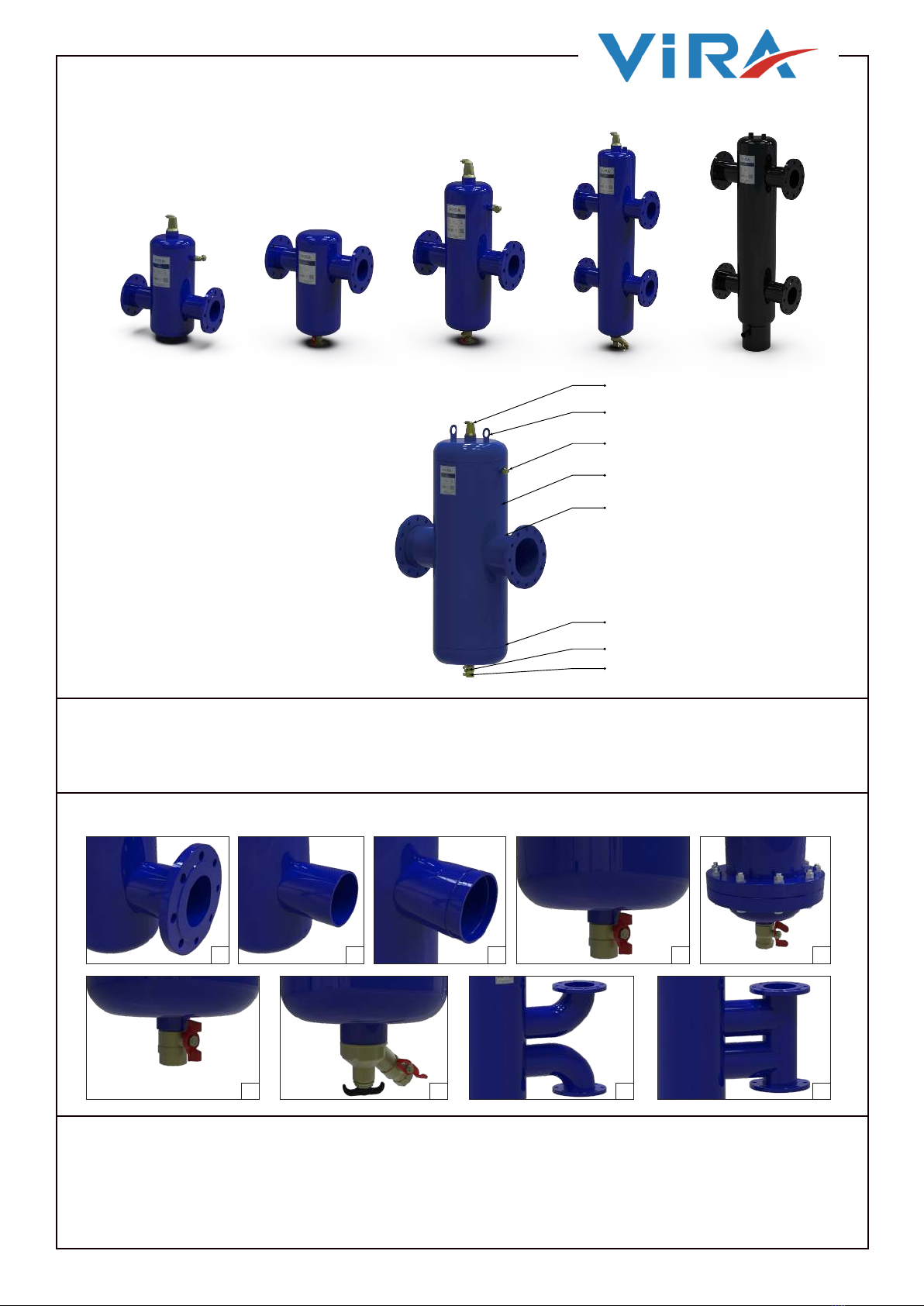
• The scum valve and the manual air valve are
designed to blow o and let in large quantities of air
during the filling and emptying of the installation and
to remove oating dirt.
5. INSTALLATION AND COMMISSIONING
5.1. Installation Conditions
• Install the unit in a frost-free, well-ventilated
place.
• Install the unit in accordance with the local
guidelines and rules.
• Install the unit stress free and with the body in
vertical position.
• Do not use the unit as a support for pipework.
• It is not allowed to weld the unit to the pipework
or other external items unless the unit is specifically
designed to be welded into the pipework.
• It is not allowed to modify the unit.
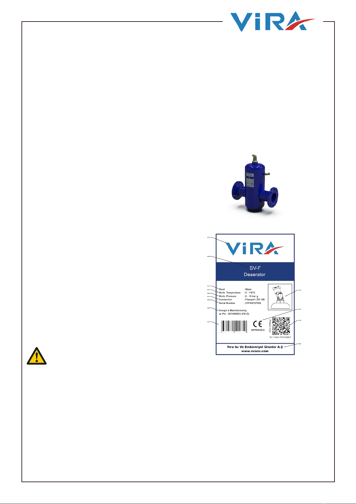
• Apply the separately supplied product labels if
the labels on the product are not visible; for instance
after the unit has been insulated.
• The lifting lugs may only be used during the
installation.
• The unit operates independent of the ow
direction.
• Do not obstruct the automatic air vent (if
available) and make sure that the automatic air vent is
always easily accessible.
• A tube can be fitted to the air vent (1/2” female
thread on the outlet) to lead away the released
(smelly) air. Excessive dirt particles or foam forming
might cause a temporary leakage of
the automatic air vent.
• If a drain pipe is fitted, make sure that this pipe
is fitted stress and vibration free to the drain valve.
Preferably, a exible pipe or pipe parts should be
used (e.g. a hose).
• Do not obstruct the vent valve and keep all valves
accessible.
5.3. Commissioning
CAUTION
If a cap R½ was installed on the automatic air
vent for the system test, make sure that cap
R½ is removed before the commissioning of
the system.
WARNING
Do not touch the unit or the pipework when the
system is in operation. The surfaces may be hot
and touching them may cause burns.
CAUTION
• Do not use the scum valve or drain valve for
(re)filling.
• Always install the unit body vertically, with
the automatic air vent (if available) on top and
the dry pocket or drain valve (if available) at the
bottom.
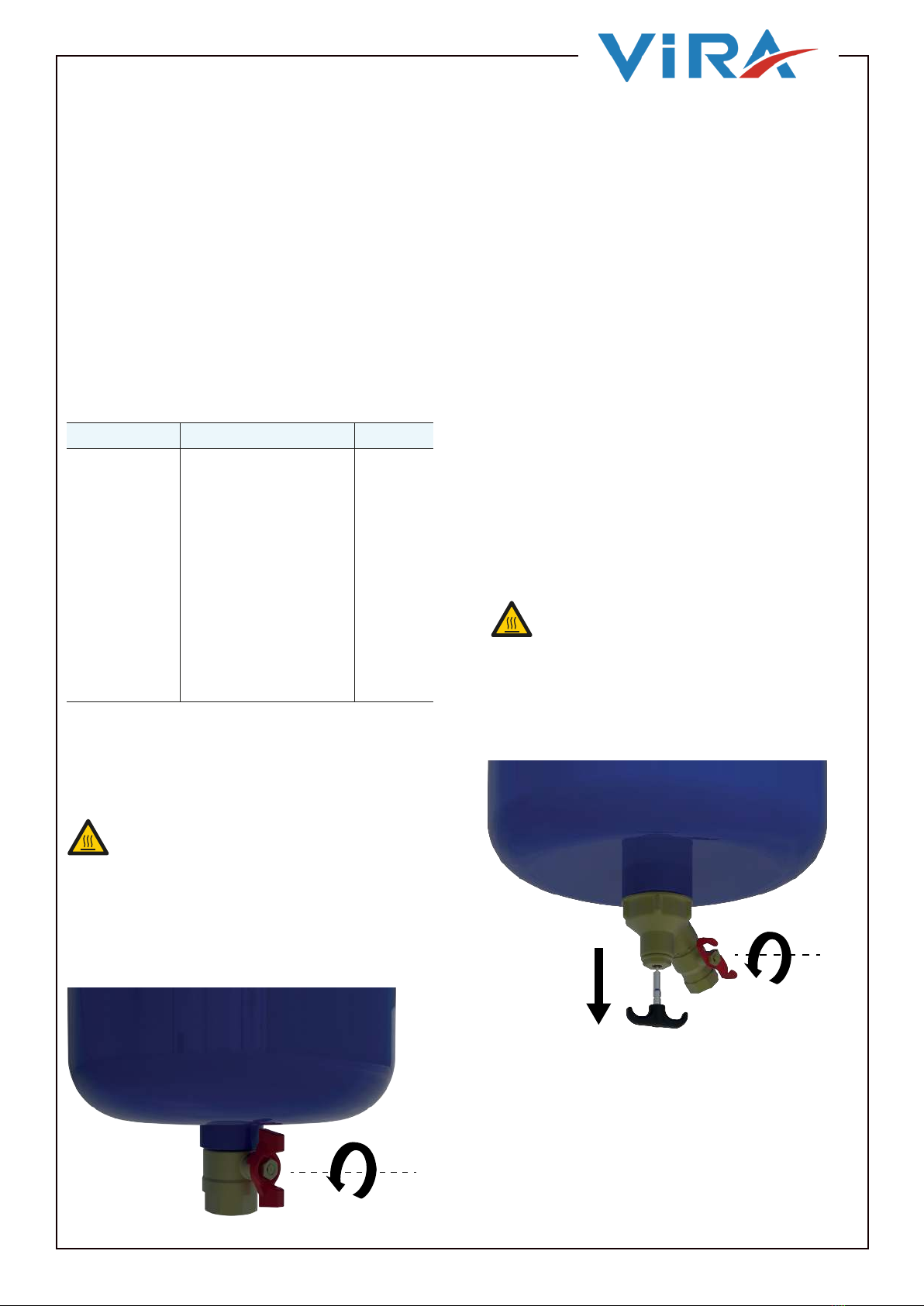
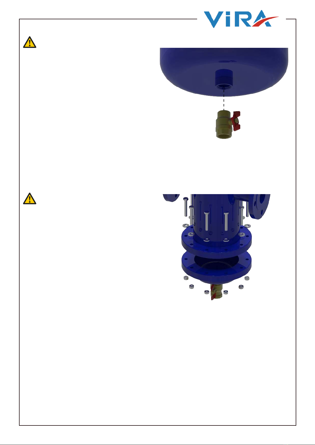
5.2.2. Install The Drain Valve (Not For SV / SVH
Units)
NOTE
For units with a drain valve and / or magnetic dirt
separator: Make sure that there is enough space to
operate the valve. In case there is not enough space
and the unit has a rotatable dirt separator, rotate the
dry pocket.
• Attach the pipework to the to the unit. Make
sure that the unit is installed stress free.
NOTE
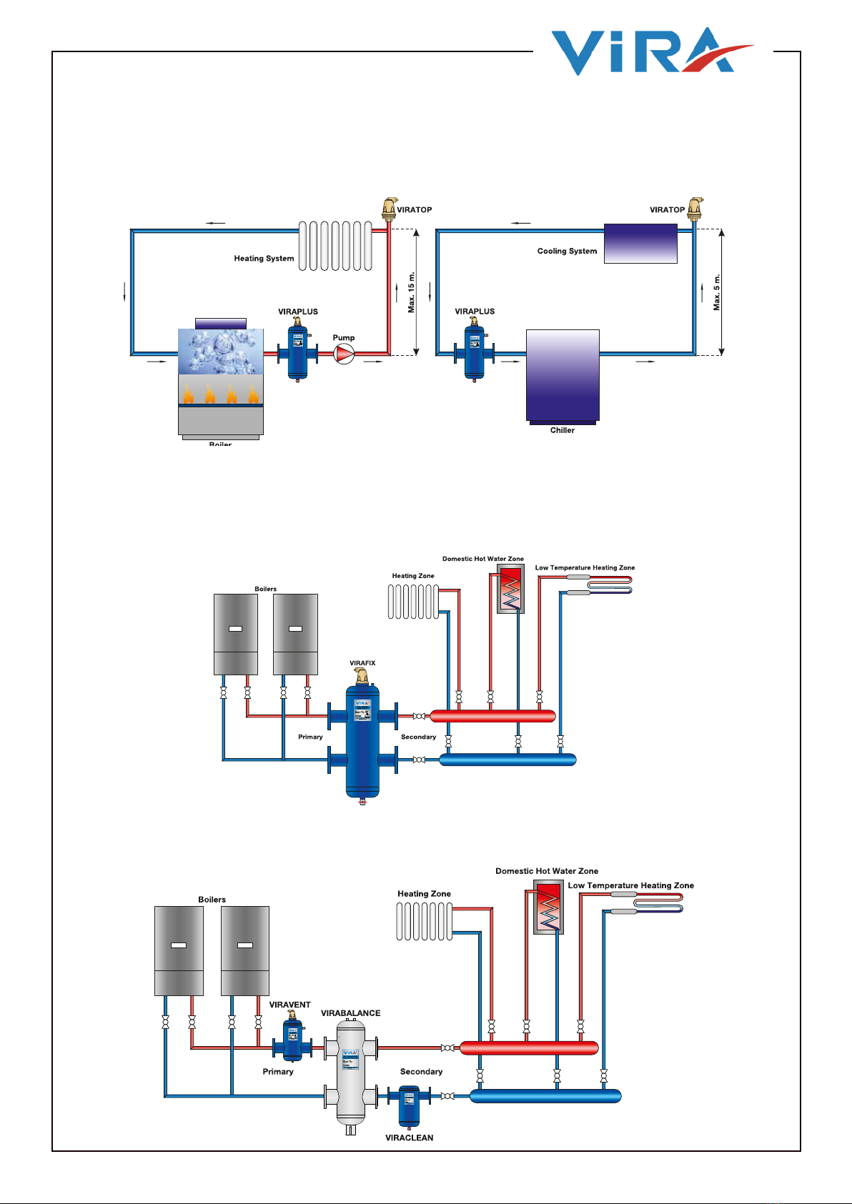
For ViraFix and ViraBalance (SCX and SB) : Make
sure that the warmest water enters the unit at the
top anges. The coldest water should enter the unit
at the lower anges. This is necessary to prevent
unwanted mixing of warm and cold water.
• Tighten the fasteners to the correct torque value
of the pipework.

7EnglishUser Manuel - 1.0
The system must be commissioned and running to
verify if the unit works properly.
At the first use, the automatic air vent (if
applicable) might temporarily drip a bit of moist,
but that is not a problem.
When the system is running, do the checks as
follows:
• Leak check
6. PREVENTIVE MAINTENANCE
6.1. Maintenance Schedule For
SXC..M/SD..M/SC..M.
TaskInterval Sect�on
Dra�n the d�rt
from the un�t
The f�rst month after
�nstallat�on and after
that on a regular bas�s,
dependent on the
amount of d�rt �n the
system:
•Normal amount of
d�rt: every 6
months
•Heavy amount of
d�rt: every 1 or 2
months
6.2
6.2. Drain The Dirt From The Unit
6.2.1. Drain The Dirt From The Unit
(For Units With A Standard Drain Valve)
WARNING
• The main body and the piping may be hot.
• Hot water or steam may escape during the
procedure.
1. Remove the safety plug.
2. Connect a hose to the drain valve. Make
sure that the hose is connected to a drain or leads
to a suitable place to collect the drained dirt.
NOTE
For the screw thread size, refer to section 3.4.
3. Gradually open the drain valve fully until
the dirt is drained out. An indication is when
clear water comes out of the unit.
NOTE
Restrict the amount of water that gets drained o.
4. Close the drain valve.
5. Disconnect the hose from the drain valve.
6. Install the safety plug.
7. Check the system pressure. If it is necessary,
refill the system.
WARNING
• The main body and the piping may be hot.
• Hot water or steam may escape during the
procedure.
6.2.2. Drain The Dirt From The Unit
(For Units Magnetic Dirt Separator)
1. Remove the safety plug.
2. Pull down the magnet’s rope
3. Connect a hose to the drain valve. Make sure
that the hose is connected to a drain.
4. Move the magnet through the unit.
• Gradually pull down the magnet in the dry
pocket.

8 English User Manuel - 1.0
6.3.3. Remove The Demountable Bottom /
Demountable Top
6.3.2. Remove The Drain Valve
6.3.1. Prepare The Unit For Cleaning Or
Replacement
1. Remove the pressure from the unit.
2. Let the unit cool down.
3. Support the bottom and ViraTube bundle with
appropiate supports, hoisting or lifting devices.
1. Drain the unit.
2. Remove the drain valve.
1. Remove the fasteners.
2. Remove the demountable bottom /
demountable top.
3. Make sure that the bottom is supported and
cannot fall.
CAUTION
Do not use force.
CAUTION
• Make sure that there is no pressure in the unit.
• Make sure that the unit is cooled down.
• Make sure that the unit is drained prior to
opening the unit.
• Do not use corrosive chemicals.
• Make sure that the unit is correctly supported.
- The ViraTube is supported by the
bottom of the separator.
- The ViraTube bundle may tumble over.
- In some cases the ViraTube bundle may
be aected by corrosion or fouling, which
may reduce the mechanical strength.
- ViraTube bundles and bottoms of the
separator may be considerably heavier due
to clogging dirt.
• Gradually let the handle return to the original
position.
• Repeat the steps one or two times for the best
result.
5. Gradually open the drain valve for a short period.
NOTE
Restrict the amount of water that gets drained o.
6. Close the drain valve.
7. Disconnect the hose from the drain valve.
8. Install the safety plug.
9. Check the system pressure. If it is necessary,
refill the system.
6.3. Clean Or Replace The ViraTube
Bundle (Only For SC/SCH And SD/SDH)

9EnglishUser Manuel - 1.0
7. INSTALLATIONS
7.1. Viraclean
Dirt Separator should always be installed before equipment (ie. boilers, ehillers, eontroll valves, pumps,
ete.) That needs proteetion from dirt, sludge, ete. In heating systems this should be in the return. In
ehilled water systems the unit must be loeated in the return elose to the ehiller.
7.2. Viravent
Viravent unit must be installed at the hottest part of the system far optimum performance. The static head
must not exceed 15m far heating system and 5m far cooling system.
The eiciency of the unit will be reduced if;
• The static head is exceeded.
• The maximum ow velocity of 3m/s is exceeded.
In heating systems the deaerator should be in the ow, preferably at the highest temperature (next to the
heat source) and low pressure if possible. Viravent, Deaerator should be installed after the boiler and on
the pump suction side, as these are the points where the formation of micro bubbles is greatest. in chilled
water systems the unit must be located in the return close to the ehiller.

10 English User Manuel - 1.0
7.3. Viraplus
Viraplus is a combination of deaerator and dirt separator which removes circulating air and micro
bubbles also dirt eectively. in heating systems the Viraplus should be in the ow and installed after the
boiler. In chilled water systems the unit must be located in the return close to the ehiller.
7.4. Virafix
lnstallation of a hydrualic separator in a heating system provides proper mixing, when ow in the boiler
circuit is dierent from ow in the distribution circuit. Also Virafix is a combination of deaerator, dirt
separator and hydrualic separator which removes circulating air and micro bubles also dirt eectively.
7.5. Virabalance
lnstallation of a hydrualic balance tank in a heating system provides proper mixing, when ow in the
boilercircuit from ow in the distribution circuit.

11EnglishUser Manuel - 1.0
8. PRODUCT DIMENSIONS
SD-F / SD-K / SD-V / SD-D
H
OD
L
h
H
OD
LF
h
ConnectionDN
ConnectionOD(mm)
L(mm)
LF(mm)
H(mm)
h(mm)
Max.Flow(L/s)
Max.Flowm3/h
Max.Flow(kPa)
FlangedWeight
WeldedWeight
H(mm)
h(mm)
Max.Flow(L/s)
Max.Flowm3/h
Max.Flow(kPa)
FlangedWeight
WeldedWeight
SD 50 168,3 330 350 373 260 3,3 12 3 16 12 521 368 5,8 21 11,8 22 18
SD 65 168,3 330 350 373 260 6,3 22,5 2,7 17 12 521 368 10 36 11,6 23 18
SD 80 219,1 450 470 509 360 8,3 30 2,9 27 21 700 545 15 54 12,4 28 22
SD 100 219,1 455 475 509 360 12,5 45 3,7 29 22 700 490 23,3 84 14,6 30 23
SD 125 323,9 605 635 700 454 20,8 75 4,2 52 44 970 710 36,7 132 16,8 58 50
SD 150 323,9 605 635 700 454 31,3 112,5 4,9 54 46 970 710 52,8 190 19,4 60 52
SD 200 400 735 775 940 640 52,1 187,5 5,8 70 55 1220 970 94,2 339 23,1 110 95
SD 250 500 860 890 1138 823 83,3 300 6,9 120 90 1580 1250 146,9 529 27,7 145 115
SD 300 600 975 1005 1458 1093 114,6 412,5 7,7 190 150 1935 1555 211,9 763 31 220 180
SD 350 700 1098 1128 1630 1242 143,8 517,5 260 210 2400 1860 288,3 1038 320 270
SD 400 800 1194 1228 1853 1415 188,3 678 343 285 2400 1860 376,7 1356 390 330
SD 450 900 1300 1330 2094 1588 238,3 858 400 330 2700 2100 476,7 1716 570 490
SD 500 1000 1400 1430 2384 1829 294,2 1059 530 440 3000 2330 588,6 2119 690 605
SD 600 1200 1600 1630 2764 2099 423,8 1525,5 650 540 3570 2780 847,8 3052 850 740
Standart;Nom.1,5m/s Hi‐Flow;Nom.3m/s
Nom.=1,5m/s Max.=3m/s

12 English User Manuel - 1.0
ConnectionDN
ConnectionOD(mm)
L(mm)
LF(mm)
H(mm)
h(mm)
Max.Flow(L/s)
Max.Flowm3/h
Max.Flow(kPa)
FlangedWeight
WeldedWeight
H(mm)
h(mm)
Max.Flow(L/s)
Max.Flowm3/h
Max.Flow(kPa)
FlangedWeight
WeldedWeight
SV 50 168,3 330 350 477 132 3,3 12 3 16 12 650 150 5,8 21 11,8 25 18
SV 65 168,3 330 350 477 132 6,3 22,5 2,7 17 12 650 150 10 36 11,6 26 18
SV 80 219,1 450 470 614 177 8,3 30 2,9 27 21 730 200 15 54 12,4 28 22
SV 100 219,1 455 475 614 177 12,5 45 3,7 29 22 730 200 23,3 84 14,6 30 23
SV 125 323,9 605 635 804 267 20,8 75 4,2 52 44 1066,5 250 36,7 132 16,8 58 50
SV 150 323,9 605 635 804 267 31,3 112,5 4,9 54 46 1066,5 250 52,8 190 19,4 60 52
SV 200 400 735 775 1004 287 52,1 187,5 5,8 70 55 1316,5 300 94,2 339 23,1 110 95
SV 250 500 860 890 1242 344 83,3 300 6,9 120 90 1676,5 360 146,9 529 27,7 145 115
SV 300 600 975 1005 1562 383 114,6 412,5 7,7 190 150 2031,5 410 211,9 763 31 220 180
SV 350 700 1098 1128 1926 416 143,8 517,5 260 210 2429,5 543 288,3 1038 320 270
SV 400 800 1194 1228 2149 456 188,3 678 343 285 2706,5 609 376,7 1356 390 330
SV 450 900 1300 1330 2390 524 238,3 858 400 330 2997,5 650 476,7 1716 570 490
SV 500 1000 1400 1430 2660 573 294,2 1059 530 440 3219,5 703 588,6 2119 690 605
SV 600 1200 1600 1630 3060 683 423,8 1525,5 650 540 3869,5 820 847,8 3052 850 740
Nom.=1,5m/s Max.=3m/s
Standart;Nom.1,5m/s Hi‐Flow;Nom.3m/s
ConnectionDN
ConnectionOD(mm)
L(mm)
LF(mm)
H(mm)
h(mm)
Max.Flow(L/s)
Max.Flowm3/h
Max.Flow(kPa)
FlangedWeight
WeldedWeight
H(mm)
h(mm)
Max.Flow(L/s)
Max.Flowm3/h
Max.Flow(kPa)
FlangedWeight
WeldedWeight
SC 50 168,3 330 350 639,5 268 3,3 12 3 19 15 880 370 5,8 21 11,8 27 20
SC 65 168,3 330 350 639,5 268 6,3 22,5 2,7 20 15 880 370 10 36 11,6 28 20
SC 80 219,1 450 470 798,5 345 8,3 30 2,9 30 24 1110 480 15 54 12,4 34 28
SC 100 219,1 455 475 798,5 345 12,5 45 3,7 32 25 1110 480 23,3 84 14,6 35 28
SC 125 323,9 605 635 1073,5 479,5 20,8 75 4,2 60 52 1540 700 36,7 132 16,8 75 67
SC 150 323,9 605 635 1073,5 480 31,3 112,5 4,9 62 54 1540 700 52,8 190 19,4 77 69
SC 200 400 735 775 1313,5 614,5 52,1 187,5 5,8 80 65 1960 920 94,2 339 23,1 120 105
SC 250 500 860 890 1581,5 812 83,3 300 6,9 136 106 2650 1250 146,9 529 27,7 184 154
SC 300 600 975 1005 1911,5 1118 114,6 412,5 7,7 216 176 3160 1510 211,9 763 31 316 276
SC 350 700 1098 1128 2709,0 1553 143,8 517,5 390 340 3570 1580 288,3 1038 440 390
SC 400 800 1194 1228 3030,0 1691 188,3 678 450 392 3900 1790 376,7 1356 520 460
SC 450 900 1300 1330 3334,0 1877 238,3 858 570 500 4330 2000 476,7 1716 630 550
SC 500 1000 1400 1430 3641,0 2065 294,2 1059 650 560 4800 2230 588,6 2119 850 765
SC 600 1200 1600 1630 4240,0 2438 423,8 1525,5 800 690 5690 2680 847,8 3052 1100 990
Standart;Nom.1,5m/s Hi‐Flow;Nom.3m/s
Nom.=1,5m/s Max.=3m/s
H
OD
L
h
H
OD
LF
h
H
OD
L
h
H
OD
LF
h
SV-F / SV-K / SV-V / SV-D
SC-F / SC-K / SC-V / SC-D

13EnglishUser Manuel - 1.0
ConnectionDN
ConnectionOD(mm)
L(mm)
LF(mm)
H(mm)
h(mm)
he(mm)
Max.Flow(L/s)
Max.Flowm3/h
Max.Flow(kPa)
FlangedWeight
WeldedWeight
SB 50 168,3 210 210 562 109 343 3,3 12 3 10 10
SB 65 168,3 330 350 862 179 505 6,3 22,5 2,7 30 18
SB 80 219,1 450 470 1242 357 657 8,3 30 2,9 43 30
SB 100 219,1 455 475 1242 357 657 12,5 45 3,7 45 31
SB 125 323,9 615 635 1535 423 819 20,8 75 4,2 72 52
SB 150 323,9 615 635 1793 478 972 31,3 112,5 4,9 120 80
SB 200 400 745 775 2197 554 1219 52,1 187,5 5,8 210 150
SB 250 500 860 890 2694 650 1523 83,3 300 6,9 350 270
SB 300 600 975 1005 3300 900 1800 114,6 412,5 7,7 420 315
SB 350 700 1098 1128 3914 1000 2103 143,8 517,5 580 460
SB 400 800 1194 1226 4320 1100 2404 188,3 678 620 496
SB 450 900 1300 1330 4830 1200 2700 238,3 858 950 786
SB 500 1000 1400 1430 5330 1300 3000 294,2 1059 1350 1165
SB 600 1200 1600 1630 6300 1500 3600 423,8 1525,5 1800 1620
Nom.=1,5m/s
Standart;Nom.1,5m/s
ConnectionDN
ConnectionOD(mm)
L(mm)
LF(mm)
H(mm)
h(mm)
he(mm)
Max.Flow(L/s)
Max.Flowm3/h
Max.Flow(kPa)
FlangedWeight
WeldedWeight
SCX 50 168,3 330 350 811,5 247,5 240 3,3 12 3 25 17
SCX 65 168,3 330 350 926,5 272,5 305 6,3 22,5 2,7 36 28
SCX 80 219,1 450 470 981,5 272,5 360 8,3 30 2,9 45 33
SCX 100 219,1 455 475 1231 345,1 464,8 12,5 45 3,7 56 38
SCX 125 323,9 615 635 1532 448 559,5 20,8 75 4,2 94 77
SCX 150 323,9 615 635 1832 543 669,5 31,3 112,5 4,9 106 84
SCX 200 400 745 775 2336 695 869,5 52,1 187,5 5,8 158 117
SCX 250 500 860 890 2886 860 1099,5 83,3 300 6,9 279 216
SCX 300 600 975 1005 3402 1020 1295,5 114,6 412,5 7,7 390 310
SCX 350 700 1098 1128 3970 1130 1420 143,8 517,5 490 400
SCX 400 800 1194 1226 4470 1280 1620 188,3 678 570 460
SCX 450 900 1300 1330 4860 1365 1830 238,3 858 660 520
SCX 500 1000 1400 1430 5400 1540 2030 294,2 1059 890 715
SCX 600 1200 1600 1630 6395 1825 2445 423,8 1525,5 1080 890
Standart;Nom.1,5m/s
Nom.=1,5m/s
H
OD
LF
L
h
he
H
OD
LF
L
he
h
SB-F / SB-K / SB-V / SB-D
SCX-F / SCX-K / SCX-V / SCX-D

14 English User Manuel - 1.0
Primary Flow Eqaul to Secondery Flow
When the system ow is equal to the secondary ow, all the
primary water is directed to the zones and all the return water
goes back to the heat source. The temperature of the zone
water is the same as that supplied by the heat source and the
return water temperature to the heat source equals the return
water temperature from the zones.ln this situation, supply and
demand are equal. Q primary = Q secondary
The Primary Flow Rate Less Then Secondary Flow Rate
When the system ow is equal to the secondary ow, all the
primary water is directed to the zones and all the return water
goes back to the heat source. The temperature of the zone
water is the same as that supplied by the heat source and the
return water temperature to the heat source equals the return
water temperature from the zones.ln this situation, supply and
demand are equal. Q primary = Q secondary
The Primary Flow Rate Greater Then Secondary Flow Rate
When the primary ow rate is greater than the secondary ow
rate, the supply temperature from the heat source will be the
temperature of the water to the zone. The return water to the
heat source will be a mix of the heat source water and zone
return water. in this situation, the power of the boiler will be
modulated downwards. Q primary > Q secondary
9. HYDRAULIC BALANCE TANK
9.1. How Works Hydraulic Balance Tank
Three operating situation can occur if a hydraulic balance tank is installed in a heating system.

15EnglishUser Manuel - 1.0
10. PRESSURE DROP
Resistance graph to ow various diameters of Smartvent Air and Dirt Separators as below.
Example:
When the water ow is 70 m3/h pressure drop far the DN 150 Smartvent Air and Dirt Separators :
1. From the ‘Flow’ axis at 70 m3/h at the point A, move vertically to the “Smartvent Dimension” DN 150
curve at point B.
2. Move left from point B to meet the “Pressure Drop” axis at point C, for this example Pressure Drop
will be 1 kPa.
PRESSURE DROP CHART
Diameter of Air & Diri Separator (DN)
Pressure Drop (kPa)
Flow (m3/h)

CONTACT US Tel : +90 212 549 57 70
Fax : +90 212 549 58 48
Email : [email protected]
Webside : www.viraisi.com
Address : İOSB, Metal İş Sanayi Sitesi 11. Blok No: 37/39
Başakşehir - İstanbul / Turkey
This manual suits for next models
15
Table of contents
Other Vira Industrial Equipment manuals
Popular Industrial Equipment manuals by other brands

PHD
PHD GRS Series REPAIR PROCEDURES

Work Area Protection
Work Area Protection SMART CUSHION INNOVATIONS SCI70GM Design & Installation Manual

Festo
Festo CP Factory Original operating instructions

Kollmorgen
Kollmorgen AKD2G-S Series Product safety guide

ABB
ABB HT842179 Operation manual

3M
3M Liqui-Cel EXF-10x28 Series Assembly and disassembly instructions