Viribus atb-e024-bk User manual
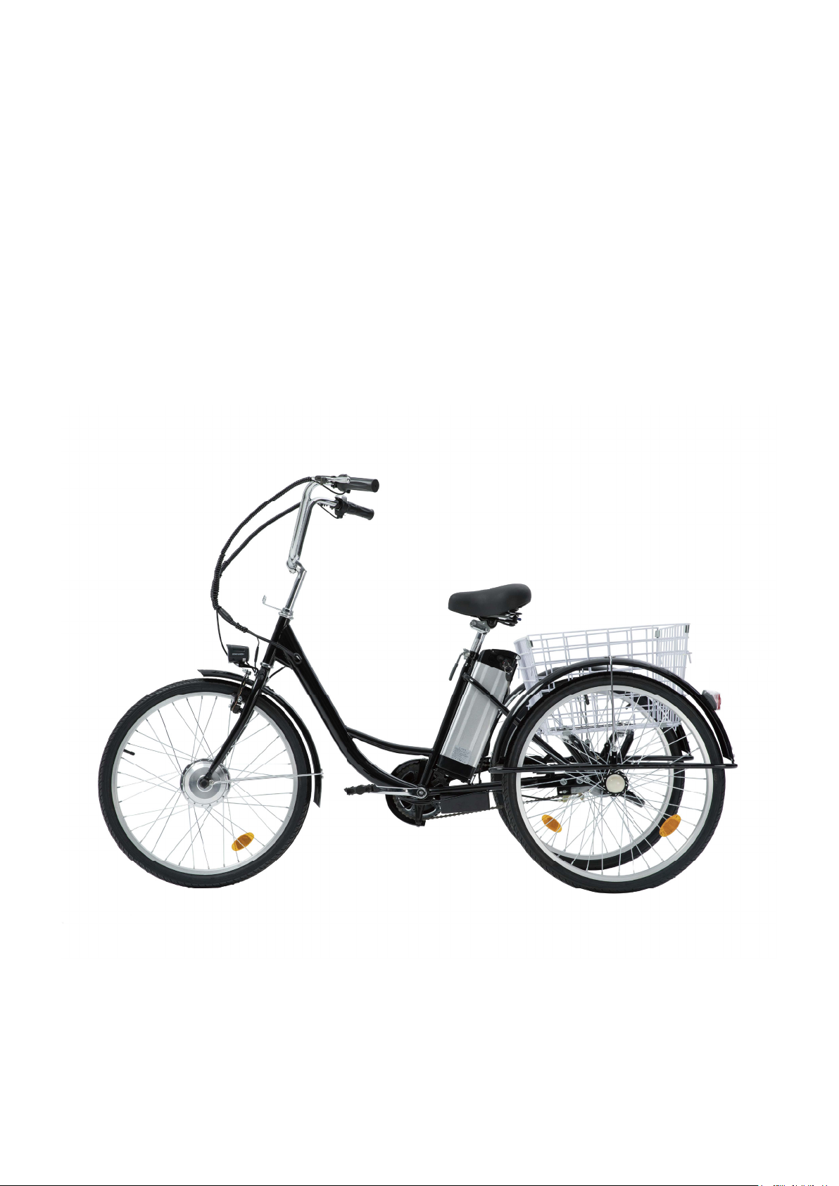
Electric Tricycle
User Manual
Read Carefully Before Use
Keep for Future Reference
V20220810

CONTENTS
Safety Information.............................................................................................. 1
Specications ..................................................................................................... 2
Package List........................................................................................................ 2
Assembly............................................................................................................. 5
1. Rear and Main Frames................................................................................... 5
2. Handlebars ..................................................................................................... 6
3. Rear Wheels................................................................................................... 7
4. Front Wheel.................................................................................................... 8
5. Chain .............................................................................................................. 9
6. Chain Guard ................................................................................................. 10
7. Seat .............................................................................................................. 10
8. Pedals............................................................................................................11
9. Rear Reectors..............................................................................................11
10. Rear Fenders, Supports, and Stays ............................................................. 12
11. Front Brake, Fender, Light, and Stay............................................................ 14
12. Rear Brake ................................................................................................... 15
13. Basket........................................................................................................... 15
14. Spoke Reectors .......................................................................................... 16
15. Battery .......................................................................................................... 16
Operation........................................................................................................... 17
Maintenance...................................................................................................... 18
Contact Information ......................................................................................... 18

1
Safety Information
• Install and adjust this tricycle ONLY in accordance with these instructions. Read them
completely prior to installation and use. Contact customer service if any point is unclear.
• ALWAYS obey all applicable local and national laws and regulations while riding. Do not ride
this tricycle in any area prohibited to electric bicycles or tricycles. Always wear your helmet
and other required protective gear. Always maintain your reectors and other required safety
equipment.
• Check whether the brakes function well using the brake levers before riding. Even after
power is cut to the motorized wheel, the inertia of the tricycle will often require active braking
power.
• ALWAYS ensure all fasteners and components are intact and securely tightened before and
after every use.
• DO NOT ride this tricycle if any part is damaged or malfunctions. Repair or replace worn and
broken parts before further use.
• Pay attention to the remaining power before setting out and during use. Recharge your
battery as needed to ensure it never runs out of power at a moment where you are taken by
surprise.
• DO NOT allow children or persons unfamiliar with these instructions to operate this tricycle
without strict supervision.
• DO NOT wear loose footwear or clothing that may become caught in the wheels or any other
moving parts.
• It is recommended that you not ride your tricycle fast until you are fully familiar with your new
electric tricycle and its controls.
• ALWAYS be alert for people, animals, or any obstacles that may appear in front of you
while riding your tricycle. Be aware that pedestrians and drivers may not expect the speed
or responsiveness of your tricycle. Adjust your behavior accordingly. It is advisable to install
warning devices to draw their attention, but always be ready to turn safely out of their way if
needed. Do not focus on the LCD display for extended periods of time while riding.
• We do not recommend that you ride your tricycle at night or in an environment with poor
visibility. If you have an emergency that makes it necessary to do so, keep your light on and
limit your speed appropriately.
• DO NOT get the battery, its charger, or its power cord wet or operate them with wet hands.
• NEVER use the pedal assist system (PAS) in any situation, road condition, or terrain where
doing so might impair your control of your tricycle.
• After each use and before any cleaning, servicing, or storage, DO NOT leave the key at “ON”
and it is strongly recommended to disconnect the power plug from the battery’s socket and
remove the battery from this tricycle to avoid any unintentional touch on the throttle, causing
the tricycle to run and bringing about accidents.
Warning!
2
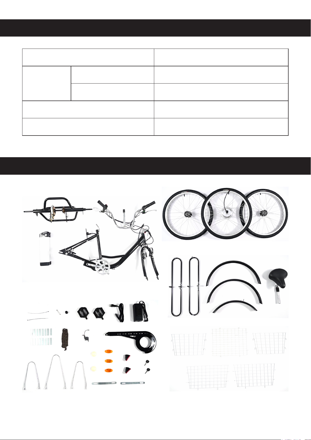
Package List
Specications
11112222
4444
55555555
99
8888
7777
6666
3333
10101010
11111111 12121212 13131313 14141414
15151515 16161616
17171717 16161818 19191919
20202020
21212121 2121212122222222
25252525 26262626
27272727
28282828
23232323 24242424
Motor Power 250W
Battery
Type 36V Lithium
Waterproof Rating IP64
Wheel Diameter 24 in. (60.9 cm)
Max. Speed 15.5 mph (25 km/h)

3
Down Tube
Seat Tube
Crank Arm
Throttle Handle
Head Tube
Front Fork
1111
2222
4444
5555
99
8888
7777
6666
3333
10101010
13131313 14141414
17171717
16161818
19191919
20202020
21212121
22222222
25252525
28282828
23232323
24242424
Emergency Stop Button
LCD Display
Item Name Qty.
1 Rear Frame 1
2 Handlebars 1
3 Battery 1
4 Main Frame 1
5 Rear Wheels 2
6 Motorized Front Wheel 1
7 Rear Fender Supports 2
8 Rear Fenders 2
9 Front Fender 1
10 Seat with Post 1
11 Zip Ties 2
12 Spring 1
13 Front Wheel Cap 1
14 Pedals 2
LCD Display
Power Button
Horn Button
Front Light Button

4
Item Name Qty.
15 Power Cord 1
16 Charger 1
17 Connecting Pieces 16
18 Chain 1
19 Front Light 1
20 Chain Guard 1
21 Rear Fender Stays 2
22 Front Fender Stay 1
23 Rear Wheel Caps 2
24 Spoke Reectors 3
25 Rear Reectors 2
26 Keys 2
27 Connecting Slats 2
28 Basket Sides 5
29 Brake Cable Caps 2
For your convenience, all bolts, nuts, and washers are pre-installed where they will be needed.
During assembly, simply remove the fasteners as needed and keep them nearby. Reinstall them
to connect each part as you go and tighten them securely for a safe and satisfactory experience.
For best results, prepare and use the following tools as needed:
• 10mm Wrench • 13mm Wrench
• 15mm Wrench • 17mm Wrench
• 18mm Wrench • 22mm Wrench
• 5mm Hex Wrench • 6mm Hex Wrench
• Phillips Screwdriver • Pliers
5
Assembly
To see these instructions in video form, go to our YouTube channel Viribus Bikes and search
for “Fixed Gear Electric Tricycle”.
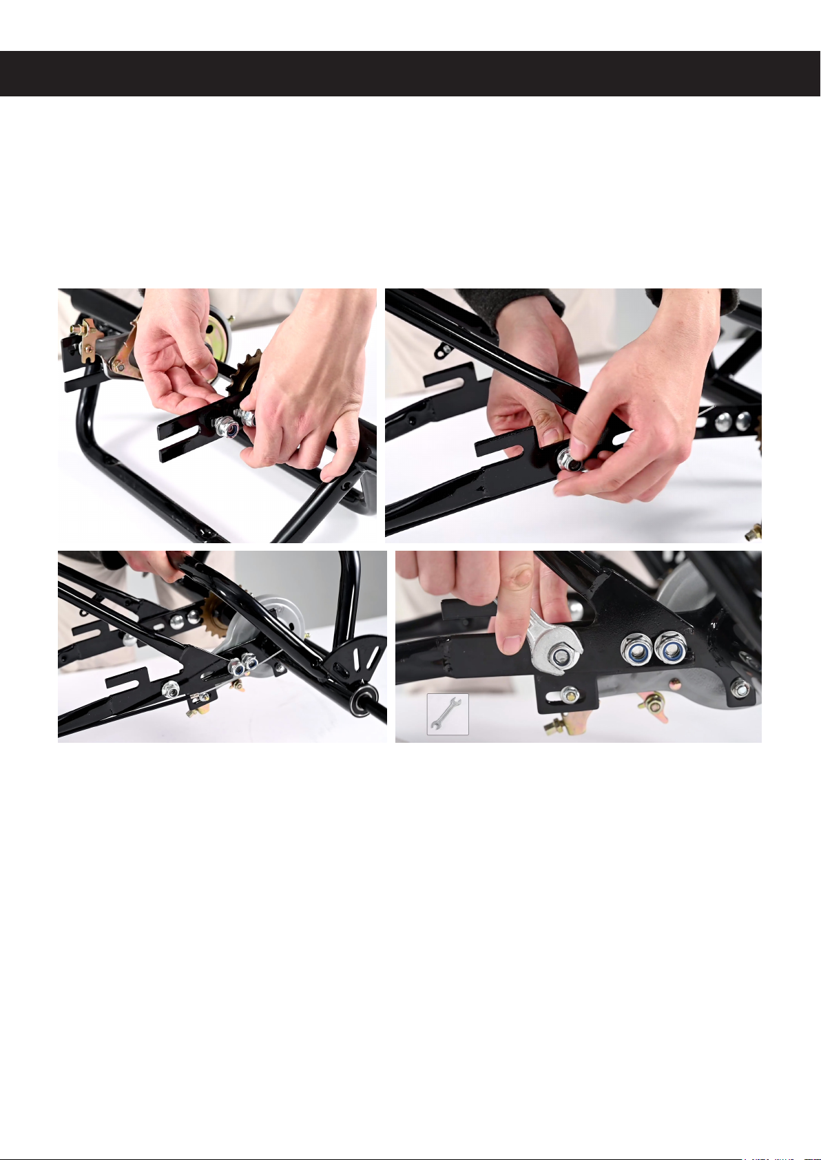
1. Connecting the Rear and Main Frames
1. Place the rear frame (1) and main frame (4) vertically on a rm level surface.
2. Loosen the 6 sets of M10 nuts and bolts on both sides of the frames, leaving slots between
the washers and the frames.
3. Align the slots of the frames with each other, sliding the rear frame onto the main frame as
shown. For best results, start with either side and repeat for the other side.
4. Partially tighten these nuts and bolts with your 17mm wrench. (Fully tighten them later after
chain installation.)

6
2. Installing the Handlebars
1. Remove the protective cover underneath the stem of the handlebars (2).
2. Loosen the M8 bolt on the top of the stem with your 6mm hex wrench.
3. Slide the stem into the head tube of the main frame, retightening this bolt.
4. Lift the handlebars to an appropriate position, tightening the M8 bolt on the front with your
6mm hex wrench.
5. Connect the blue cables from the main frame to the throttle on the right handlebar.
6. Connect the red brake cables from the correct handlebars to the correct brakes. (Left to the
front brake and right to the rear brake in the United States.)
7. Bind these cables using the zip ties (11).

7
3. Installing the Rear Wheels
Note: The two rear wheels (5) ARE dierent and should NOT be mixed up. The wheel with the
O-shaped slot goes with the O-shaped hub on the rear axle while the wheel with the D-shaped
slot goes with the D-shaped hub.
1. Remove the M14 nut and 2 washers from the O-shaped hub. Place them nearby.
2. Slide the spacer back into place on the O-shaped hub, if needed.
3. Insert the wheel with the O-shaped slot onto the O-shaped hub.
4. Replace the washers and nut, tightening the nut with your 22mm wrench.
5. Remove the M14 nut and 2 washers from the D-shaped hub. Place them nearby.
6. Insert the wheel with the D-shaped slot onto the D-shaped hub.
7. Replace the washers and nut, tightening the nut with your 22mm wrench.
8. Attach the rear wheel caps (23) to both wheel hubs, pressing hard until they are locked in
place.

8
4. Installing the Front Wheel
1. Loosen the M12 nuts on both sides of the motorized front wheel (6).
2. Press and disconnect the V-shaped front brake on the main frame’s front fork.
3. Fit the front wheel into the front fork, keeping the motor cable on the right.
4. Retighten the nuts with your 18mm wrench.
5. Connect the wiring between the motor and the main frame.
6. Cover the nut on the right with the attached cap.
7. Attach the front wheel cap (13) to the nut on the left, pressing it hard until it is locked in place.
Table of contents


