Virtuox VPOD User manual

VPOD-H Product Features:
• FDA Approved
• Data storage and transmission to VirtuOx
Laboratory for Oxygen Qualification
• Data storage and transmission to VirtuOx
O.E. Office Edition for Non Qualification
• USB interface for data transfer
• 72 hours of data storage
• High Resolution Pulse Oximetry
(Records at 1 second intervals)
• Three display modes
• Special design for sleep monitoring
• LCD Displays SpO2, SpO2 waveform & Pulse Rate
• Low power consumption, uses 2 AAA battery
• Battery low indicator
• 3 year warranty
Call Toll-Free 877-337-7111 • https://www.virtuox.net
No cost software + low cost oximeters =
The industry’s most cost effective way to qualify oxygen patients!
The VirtuOx Total Solution

Vpod Instruction Manual
1
Copyright
Our company owns all rights of this unpublished work and intends to maintain it as a confidential work.
We may also seek to maintain this work as an unpublished copyright. This publication is to be used
solely for the purpose of reference or operation of our software system. No part of this work can be
disseminated for other purposes.
In the event of inadvertent or deliberate publication, we intend to enforce its right to this work under
copyright laws as a published work. Those having access to this work may not copy, use, or disclose
the information in this work unless expressly authorized by our company.
All information contained in this publication is believed to be correct. We shall not be liable for errors
contained herein nor for incidental or consequential damages in connection with the furnishing,
performance, or use of this material. The information this publication refers to is protected by
copyrights or patents and does not convey any license under the patent rights of our company, nor the
rights of others. We do not assume any liability arising out of any infringements of patents or other
rights of third parties.
Contents of this manual are subject to changes without prior notice.
All rights reserved.
Version: V1.0I12
Issue Date: 3rd of August, 2009
Content
CHAPTER 1 INTRODUCTION................. 2
1.1
B
RIEF
I
NTRODUCTION
.......................... 2
1.2
S
AFETY
I
NFORMATION
......................... 2
1.3
E
QUIPMENT SYMBOL
............................ 3
1.4
E
LECTROMAGNETISM INTERFERENCE
. 4
1.5
E
QUIPMENT CLASSIFICATION
............... 4
1.6
I
NTENDED
U
SE
..................................... 4
1.7
P
RODUCT FEATURES
........................... 4
1.8
A
CCESSORY
......................................... 4
CHAPTER 2 BASIC OPERATION .......... 5
2.1
O
UTER
V
IEW
........................................ 5
2.2
R
EAR
P
ANEL
........................................ 5
2.3
C
ONNECT THE SENSOR
........................ 6
CHAPTER 3 SETUP BEFORE OPERATION 6
3.1
P
OWER ON THE OXIMETER
................... 6
3.2
E
NTER
“S
ETTING MODE
”.................... 6
CHAPTER 4 TAKE A MEASUREMENT. 7
4.1
M
ONITORING
........................................ 7
4.2
M
ODE SWITCH
...................................... 7
4.3
F
ACTORS THAT MAY AFFECT THE MEASUREMENT
7
4.4
D
ISPLAY MODE
..................................... 8
CHAPTER 5 OTHER INFORMATION .... 8
5.1
A
LARM
................................................. 8
5.2
A
BOUT THE BUTTON
............................ 8
5.3
D
ATA REPLAY AND TRANSMISSION
...... 9
5.4
M
AINTENANCE
..................................... 9
5.5
T
ROUBLESHOOTING
............................. 9
APPENDIX A SPECIFICATIONS........ 12
APPENDIX B............................................. 12
GUIDANCE AND MANUFACTURER'S DECLARATION - ELECTROMAGNETIC IMMUNITY 13

Vpod Instruction Manual
2
Chapter 1 Introduction
1.1 Brief Introduction
Thank you for purchasing the handheld pulse oximeter. The device is designed to measure SpO
2
and
PR, delivering visual and audio alarm, sensor off alarm. Please read this manual carefully before using
it.
Notice: The illustrations used in this manual may differ slightly from the appearance of the actual
product.
Measurement principle
The principle of pulse oximetry is based on the red and infrared (IR) light absorption of oxygenated
and deoxygenated hemoglobin present in the circulating blood. Oxygenated hemoglobin absorbs
more IR and allows more red light to pass through. Deoxygenated hemoglobin conversely absorbs
more red light and allows IR light to pass through. The detector probe is placed on the finger. The
probe contains two light emitting diodes (LED’s), one in the visible red spectrum. The beams of light
from this probe pass through the tissues and some light is absorbed by the blood and soft tissues
depending on hemoglobin concentration. The amount of light absorption at each light frequency is
dependent on the degree of oxygenation of hemoglobin within the tissues.
The microprocessor can select out the absorbance of the pulsatile fraction of blood, i.e. that due to
arterial blood, from constant absorbance due to non-pulsatile venous or capillary blood and other
tissue pigments
Basis of Operation
1. Red and Infrared-ray Emitter Diode
2. Red and Infrared-ray Receptor Diode
1.2 Safety Information
Conception of Warning, Precaution and Notice
Warning - Indicates a potential hazard or unsafe practice that, if not avoided, will result in
death or serious injury.
Precaution - Reminds the user to pay close attention to device operation, failure of which
may cause abnormal function of the instrument.
Notice - Informs the user of other important information by suggestion, requirement and
supplement.
Warnings
Please read this manual carefully before using this device. The user must check that the equipment
functions safely and ensure that it is in proper working condition before being used.
To avoid explosion hazard, do not use the oximeter in the presence of flammable anesthetics,
vapors or liquids.
Do not open the equipment housings; electric shock hazard may exist. All servicing and future
upgrades must be carried out by the personnel trained and authorized by our company only.
Do not use the pulse oximeter in an MRI or CT environment.
The pulse oximeter is specified for use by medical professionals only.
Prolonged use of the probe/sensor or the patient’s condition may require changing the sensor site
periodically. Change the sensor site and check skin integrity, circulatory status, and correct
alignment at least every 4 hours. Prolonged use may cause blisters, skin deterioration, and
discomfort.
Sensor malfunction may cause inaccurate data, possibly resulting in patient injury or death. Pay
close attention to the sensor and inspect it often.

Vpod Instruction Manual
3
When connecting this oximeter to any instrument, verify proper operation before clinical use. Refer
to the instrument’s user manual for full instructions. The equipment connected to the pulse
oximeter’s data interface must be certified according to the respective IEC standards, i.e., IEC950
for data processing equipment or IEC 601-1 for medical electrical equipment. All combinations of
equipment must be in compliance with IEC601-1-1 systems requirements.
The physiological data and alarm messages displayed on the equipment are for reference only and
cannot be directly used for diagnostic interpretation.
Worn-out data cables may also cause inaccurate data, so if the data is used as a reference to treat a
patient, pay special attention to data cable and check it more frequently.
When using the equipment with electrosurgical units (ESU), make sure the patient is safe.
Do not come into contact with the patient during defibrillation. Otherwise serious injury or death
could result.
Single-use accessories should never be reused.
Precautions
Autoclaving, ethylene oxide sterilizing, or immersing the sensors in liquid may cause inaccurate
readings.
The operator must be thoroughly familiar with the information in this manual before using the device.
Unplug the sensor from the oximeter before cleaning or disinfecting it.
If liquid is accidentally spilled on the unit, clean and dry thoroughly before reuse.
Do not try to use the SpO
2
and NIBP measurement on the same arm at the same time. This could
potentially affect measurement accuracy.
Notices
Operation of this device in an electromagnetic field may influence its accuracy.
SpO
2
measurements may be influenced by high ambient light, especially sunlight. Shield the sensor
area if necessary.
Dyes introduced into the bloodstream, such as methylene blue, indocyanine green, indigo carmine,
and fluorescein, may influence the accuracy of the SpO
2
reading.
Any condition that restricts blood flow, such as use of a blood pressure cuff or extremes in systemic
vascular resistance, may cause a failure to determine accurate pulse rate and SpO
2
readings.
Remove fingernail polish or artificial fingernails before applying SpO
2
sensors. Fingernail polish or
artificial fingernails may cause inaccurate SpO
2
readings.
Optical cross-talk can occur when two or more sensors are located in adjoining areas. It can be
eliminated by covering each site with opaque material. Optical cross-talk may adversely affect the
accuracy of the SpO
2
readings.
Obstructions or dirt on the sensor’s red light or detector may cause a sensor failure. Make sure there
are no obstructions and the sensor is clean.
For routine equipment maintenance, please refer to the service procedures at the associated section
as indicated in the manual.
As to the other concerns for attention, please carefully look through the specific chapter in this
instruction.
1.3 Equipment symbol
Symbols
Definition
Attention !Refer to the
relevant the prompt. Read
the operator’s manual
carefully before using the
oximeter.
Type BF applied part
Date of Manufacture

Vpod Instruction Manual
4
Manufacturer’s information.
Low power indicator
IPX1 Protected against dripping
water
1.4 Electromagnetism interference
This oximeter is designed and tested in compliance with the EMC standard, complying with the
international standard for the EMC of the electronic medical device - IEC 60601-1-2. However,
because of the proliferation of radio frequency transmitting equipment and other sources of electrical
noise in the health-care and home environments (e.g. cellular phones, mobile two-way radios,
electrical appliances) it is possible that high levels of such interference due to close proximity or
strength of a source, may result in disruption of performance of this device.
This apparatus complies with the IEC 60601-1-2 international standard. The requirements of this
international standard are: CISPR11, GROP1, and CLASS B.
1.5 Equipment classification
Classification according to IEC-60601
According to the type of protection against
Electrical shock: Internal electrical power source equipment
According to the degree of protection
against Electrical shock: Type B equipment
According to the degree of protection
against harmful ingress of water. Ordinary equipment(enclosed equipment without
protection against ingress of water)
According to the methods of sterilization
or disinfection Non-sterilizable: Use of Liquid surface disinfectants
only.
According to the mode of operation: Continuous operation
Equipment not suitable for use in the presence of a flammable anesthetic mixture air or with
oxygen or nitrous oxide.
1.6 Intended Use
The purpose and function of the handheld pulse oximeter is to indicate measure and display the
functional oxygen saturation of arterial hemoglobin (SpO
2
) and pulse rate for adults and pediatric
patients in hospital, ambulatory, home, and EMS (emergency medical service) environments. The
pulse oximeter is intended for spot-checking these levels and not indicated for continuous monitoring.
It can assist the clinician diagnostically by quickly displaying the patient’s SpO
2
% and pulse rate and
can additionally store 72 hours of data.
1.7 Product features
Compact, lightweight design and simple operation
Color OLED with adjustable backlight displays SpO
2
, pulse rate and pulse bar
Up to 10 patient ID and 72-hour record storage, visual & audio alarm, low battery alarm
Data transfer to PC for storage or printing
Convenient 2 AA size alkaline batteries
Suitable for adult and pediatric patient
1.8 Accessory
Standard accessories:
Operator’s manual
VPROBE V_SOFT Finger sensor: compatible with The VPOD
Two AA-Size Alkaline batteries
Subscription to Virtuox
Optional accessories:
1. Finger sensor for adult
2. SpO
2
sensor for pediatric and infant
3. Software license
4. Data cable for transmission to Virtuox
5. 2 year extended warranty
Confirm that the items listed are packed with the pulse oximeter. If any item on this list is missing or
damaged, contact your distributor. Contact the carrier immediately if the shipping carton is damaged.

Vpod Instruction Manual
5
CHAPTER 2 BASIC OPERATION
2.1 Outer View
Fig.1
Description of Fig.1:
::
:
1— Double-functional socket:for oximeter probe and data transfer cable.
— Oximeter probe socket: Connect the probe with the oximeter before taking a measurement.
— Data cable socket: Connect the oximeter with PC by a data cable for transferring data recorded
to Virtuox software.
2— The function button: short press the button to change the display mode on the measurement
screen; And on the normal screen, extended press the button for about 4 seconds to change the
setting items.
3— The POWER on/off button
Note:If no press on any button for 30 seconds, the oximiter will power off automatically.
4— The Setting button: Press this button repeatedly to increase the parameter under adjustment by
one decrement.
5— Display screen, displays date and time, SpO
2
data, PR data, error information etc.
2.2 Rear Panel
Fig.2
Install the batteries
The oximeter can be powered by 2 AA-Size alkaline batteries (which will typically provide 50 hours of
continuous operation), or by the optional rechargeable battery pack.
When battery power is lower than 2.7±0.1V, the sign
will flicker in its display area. Replace the
battery (or rechargeable batteries) as soon as possible. The installation steps are shown as Fig. 2.3.
Be sure to insert the batteries in the correct polarity, as indicated by polarity marking (+ and -)

Vpod Instruction Manual
6
inside the battery compartment.
Fig. 3
Cautions!
Be sure to install batteries with correct polarities.
Only use the approved batteries.
Do not use batteries not specified for this unit.
Do not dispose of batteries in fire.
If battery fluid gets on your skin or clothing, rinse with plenty of clean water immediately.
Remove the batteries from this unit when you are not going to use it for a long period of time
(approximately one month).
Do not use batteries of a different type together.
Do not use new and used batteries together.
Dispose of batteries in accordance with the local ordinances and regulations.
2.3 Connect the sensor
Connect the oximeter sensor to the top of the oximeter as shown in Fig. 4. Ensure that the sensor is
firmly plugged in.
Fig. 4
Notice:
The connector is also applied to upload data to Virtuox software for managing data.
CHAPTER 3 Setup before Operation
3.1 Power on the oximeter
Short press the Power button to power the oximeter on.
Notice: To maintain the highest degree of accuracy, it is recommended that the finger and the
oximeter sensor/probe should be kept as still as possible.
3.2 Enter “Setting mode”
Press the function button for about 4 second (extended press), the oximeter will enter into “Setting
mode” and you will find a parameter item which include its title and value on the top right corner of the
display (refer to Fig.5).
After entering the setting mode from the normal screen, continually press Function button, the current
parameter item will be changed sequentially in the following order:
Br(brightness) -->ID(patient’s ID) -->Y(year) -->M(month) -->D(date) -->H(hour) -->m(minute)
-->S(second) --Br(brightness)-->...
Fig.5
Notice: When setting date and time, please don’t insert finger.
b) Save and exit from “Setting mode”
①Under the “Setting mode”, press “function key (left key)” to select the desired parameter item.
②Then press “Setting key (right key)” to adjust the value.
Each time when you press the “Setting key (right key)”, current parameter value will be added by 1 unit
sequentially.
Double press the “Setting key (right key)” and the current parameter setting will be added by 10 units
sequentially. All use circular logic.
③Press “function key (left key)” to select the next desired parameter item. Then redo step ②to
adjust the value. You can continually redo step ①to ②until no parameter’s setting need to be
changed.
④To finish setup, fleetly press both left and right keys together to confirm. Then the modifications

Vpod Instruction Manual
7
under the “Setting mode” will be saved, at the same time, the system will exit from “Setting mode”.
Notices:
1. To confirm the modification, the act of pressing both buttons simultaneously must be fleet. Do not
press them for long time.
2. When setting date and time, please don’t insert finger.
Cancel and exit from “Setting mode”
Under the Setting mode, double-press the Function button, the modification under “Setting mode” will
be cancelled and simultaneously, the system will exit from “Setting mode”.
If there is no operation under Setting mode” for more than 30 seconds, the system will exit from
“Setting mode” automatically.
CHAPTER 4 Take a measurement
4.1 Monitoring
SpO
2
measuring is a non-invasive technique used to measure the amount of oxygenated hemoglobin
and pulse rate by measuring the absorption of selected wavelengths of light. The light emitted by a red
and infrared light-emitting diodes passes through the tissue and is converted into electrical signals by
a photodiode.
After finishing the settings contained in chapter 3, plug your finger into the sensor shown as the
following picture:
Fig 6 placement of the sensor
Select the suitable sensor in terms of type and dimension.
Clip the sensor to the rational position of the patient finger. And ensure that the patient’s nail
surface is facing upward.
Plug sensor into SpO
2
port on top panel of pulse oximeter.
Notice: To maintain the highest degree of accuracy, it is recommended that the finger and the
oximeter sensor/probe are kept as still as possible.
4.2 Mode switch
After turning on the oximeter, each time the function button is pressed, the oximeter will switch to
another display mode, shown as Fig.7.
4.3 Factors that may affect the measurement
During operation, the accuracy of oximeter readings can be affected by the following factors:
4.3.1 Instrument performance depends on the pulsatile character of the artery. The measurement
would not be considered reliable and accurate if the following conditions are present during
measurement:
Shock or cardiac arrest
Temperature of the digit
After the administration of a cardiovascular drug
Anemia
Evidence of ventilation-perfusion mismatch
4.3.2 Instrument performance depends on the wavelength absorption for oxyhemoglobin and
deoxyhemoglobin. If there are substances absorbing the same wavelength, this would induce false or
low SpO
2
values. The following may affect these values:
carboxyhemoglobin
methemoglobin
methylene blue
Indigo carmine
4.3.3 Extremely high illumination could affect the SpO
2
measurement. Use a semi-translucent or
opaque cover to shield the sensor.
4.3.4 Other factors
a) High-frequency electrosurgical interference from external devices, including defibrillators.
b) Placement of a sensor on an extremity that currently has installed a blood pressure cuff, arterial
catheter, or intravascular line;
c) The patient has hypotension, severe vasoconstriction, severe anemia, or hypothermia;
d) An arterial occlusion proximal to the sensor.
Warnings
Use only SpO
2
sensors provided by manufacturer. Other SpO
2
sensors may cause improper
performance.
Do not use an SpO
2
sensor with exposed optical components.
Excessive patient movement may cause inaccurate measurements.
Tissue damage can be caused by incorrect operation or misusing sensor; for example, by

Vpod Instruction Manual
8
wrapping the sensor too tight. Inspect the sensor site to ensure the skin’s integrity and the
adhesion position of the sensor is correct. More frequent inspection should be taken if necessary.
Loss of pulse signal can occur in any of the following situations:
a) The sensor is too tight;
b) There is excessive illumination from light sources such as a surgical lamp, a bilirubin lamp, or
sunlight;
c) A blood pressure cuff is inflated on the same extremity as the one to which an SpO
2
sensor is
attached.
4.4 Display mode
The handheld pulse oximeter uses an OLED display for a readout. It can display the SpO
2
and pulse
rate (PR) value, as well as a pulse column and SpO
2
waveform.
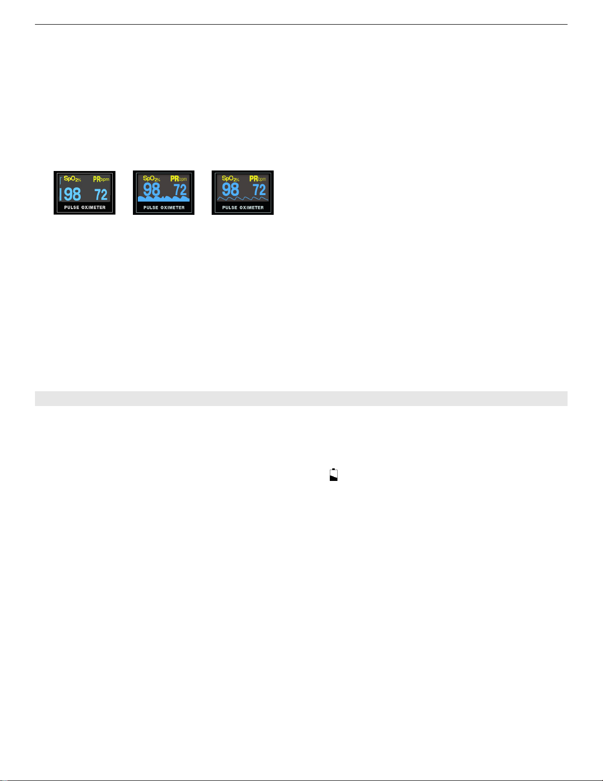
There are three display modes shown in Fig 7. The first figure is pulse column display mode. The
second figure is the waveform mode. The third figure is line waveform mode indicating SpO
2
% trend.
(1) (2) (3)
Fig.7 Three display modes
SpO
2
:Percent oxygen saturation value displayed above is 98%
PR: Pulse rate value displayed is 72 bpm
Fig.7(1) Pulse column: This is used for signal identification and quality indication during motion
and low signal to noise situations. The bar rises and falls with the pulse, its height indicating
signal quality. When the bar is very low, the SpO
2
and pulse rate values may be suspect.
Fig.7(2) Filling-up SpO
2
plethysmogram wave: SpO
2
plethysmogram measurement is
employed to determine the oxygen saturation of hemoglobin in the arterial blood. If , for example,
98% hemoglobin molecules in the red blood cells of the arterial blood combine with oxygen, then
the blood has a SpO
2
oxygen saturation of 98%. The SpO
2
numeric on the Oximeter will read
98%, refer to Fig.7.(2). The SpO
2
numeric shows the percentage of hemoglobin molecules which
have combined with oxygen molecules to form oxyhemoglobin. The SpO
2
plethysmogram
measurement can also provide a plethysmogram wave. During this mode, the PR tone is dumb.
Fig.7(3) SpO
2
plethysmogram wave
PR tone modulation: Beeps in sync with the patient’s pulse, even under most challenging
patient motion conditions.
CHAPTER 5 Other information
5.1 Alarm
Alarm: Technical alarm and physiological alarm.
Technical alarm: finger out, probe off, power low and error code.
In the situation that the finger is not inserted correctly or the connection state of the probe is not good
results in failure of measurement, “Finger out” or ”Sensor off” may be displayed on the normal screen.
When battery power is lower than 2.7±0.1V, the sign will flicker in its display area. Replace the
batteries as soon as possible.
In the failure state, the oximeter will display error codes, and will automatically power off if the error
code display lasts for more than 8 seconds. For the details and definitions on error, please refer to
chapter 4.2.
Physiological alarm: SpO
2
and PR
If the measured SpO
2
and/or PR value is beyond the default limit, alarm will be activated, and the
corresponding value will flash with audio alarm “didi—didi….” .
By default:
SpO
2
: The upper limit: 100%
The lower limit: 90%
PR: The upper limit: 100bpm
The lower limit: 60bpm
Note: during the alarm is issued, long press the functional button, you can silence the alarm for 30
seconds.
5.2 About the button
1) Definition of button
There are three buttons in the oximeter: Power button, Function button and Setting button.
Power button: This acts as a Power On switch when the unit is in an Off condition.
Function Button: When the unit is On, it acts as a Function button.
Setting button: Located at the right of the oximeter, it has no function when the power is off. When
the unit is On, it acts as a Setting button.
2) Definition of Button Press
There are three ways to press the button:
Short Press: press the button quickly, the duration time should no more than 1 second.
Double press: Two-time continuous press, the time between the two press actions should be no more
than 0.5 second.

Vpod Instruction Manual
9
Extended press: Press the button for more than 1.5 seconds.
Long press: Press the button for more than 2 seconds.
5.3 Data replay and transmission
The oximeter can record SpO
2
and PR value for more than 72 hours, but the oximeter itself has no
data replay function. You can transmit the history data to a PC using “Virtuox” software and a special
data cable. As for detailed setup and operation, please refer to the “Virtuox” website.
www.virtuox.net
Note: Virtuox can be obtained at no charge with the purchase of this device. Please contact Virtuox
customer service to set up an account. 877-337-7111
5.4 Maintenance
It is very important for user to perform daily maintenance of oximeter and parts in order to maintain its
function and appearance. Disinfection procedures may be performed with the use of the below
mentioned cleaner/disinfectants. Failure to perform these procedures may result in invalidating the
warranty. Local disinfection protocols will apply.
Please take out battery before cleaning the oximeter.
The external surface of the oximeter can be cleaned by wiping with a damp cloth. Do not submerge
the oximeter in any solution at any time. To do so will void the warranty
Use the following permitted solutions:
Ammonia (diluted)
Glutaraldehyde
10% Bleach solution
Mild soapy water (diluted).
Do not use the following cleaners:
○Any kind of scrubbing or scouring solution
○Acetone
○Alcohol-based cleaners
Probe cleaning and disinfecting
1. Clean or disinfect the sensor before each use.
2. Unplug the sensor from the oximeter before cleaning and/or disinfecting.
3. Clean the external sensor surfaces and patient contact surfaces with a soft cloth moistened
with water or a mild detergent solution.
4. To disinfect the sensor, wipe the surfaces with a disinfecting solution. Isopropyl alcohol is
recommended
5. Do not immerse the sensor in any solution. To do so will void the warranty.
6. Do not sterilize the sensor by irradiation, steam autoclaving or ethylene oxide
Battery maintenance
Remove the batteries if you will not be using the oximeter for a long time.
Charge the batteries (Ni-MH) fully prior to storage.
Please charge over 14 hours at first time, or will reduce the battery life.
5.5 Troubleshooting
a) Error Definitions
Err 1: program memory damaged.
Err 2: data memory damaged.
Err 3: sensor Red Emission Diode damaged.
Err 4: sensor Infrared-ray Emission Diode damaged.
Err 5: sensor Infrared-ray Receipt Diode damaged.
Err 6: exterior crystal oscillator damaged.
Err 7: sensor emission diode or receipt diode damaged.
Err 9: real time clock damaged.
Err 10: EEPROM chip damaged.
b) Possible problem and corresponding resolution
Probl
ems Possible
reason Solution
SpO
2
or PR
canno
t be
displa
yed
norma
lly
1. Finger is not
plugged
correctly
2. Patient’s
Oxyhemoglo
bin value is
too low to be
measured
1. Retry by
plugging the
finger
2. Attempt
several time
to obtain a
reading, If
are sure
that no
problem
exists,
obtain
further
clinical
examination
SpO
2
or PR
displa
y is
unsta
1. Finger might
not be
plugged
deep enough
2. Finger is
1. Retry by
plugging the
finger
2. Urge the
patient to

Vpod Instruction Manual
10
ble trembling or
patient is
moving
continually
remain still
The
Oxim
eter
can
not be
power
ed on
1. Battery
power may
be
inadequate
or not
installed
2. Batteries
might be
installed
incorrectly
3. The
Oximeter might
be damaged
1. Please
replace
batteries
2. Please
reinstall the
batteries
3. Contact local
customer
Technical
Service
“Error
3” or
“Error
4”
Displa
yed
on
scree
n
1. Receiving
diode may be
shielded or
damaged
together with
broken
connector.
2. Mechanical
Misplace for
receive-emis
sion diode
3. Amp circuit
malfunction.
1. Contact local
customer
Technical
Service
2. Contact local
customer
Technical
Service
3. Contact local
customer
Technical
Service
“Error
7”
displa
yed
on
scree
n
1. Emission
diode
damaged.
2. Current
control circuit
malfunction.
1 Contact local
customer
Technical
Service
2 Contact local
customer
Technical
Service
“Prob
e off”
displa
yed
on
scree
n
1. The sensor
is not
connected
2 The
connection
between the
Probe and
Oximeter is
loose
1. Connect the
sensor
2. Please
check if the
probe was
connected with
oximeter
correctly
5.5.1 Service Method
a)Service hours: 9:00am~5:30pm, Monday - Friday
b)Service support: Telephone and e-mail support.
Parts Replacement: Virtuox will replace parts if necessary free of charge during the warranty period.
5.5.2 Exemptions and limitations:
a) Not responsible for damage caused by force majeure. For example: fire, lightning, flood, cyclone,
hail and earthquake.
b) Warranty expiration. The corresponding cost of insurance, disassembling, refurbishing,
repackaging and shipping the oximeter or its components
c) Damage caused by a third party
d) Damage and caused by user or its representative not in compliance with the operator’s manual.
e) The oximeter is installed or connected with such external device without our company permission
as printer, computer, netline and lead to oximeter failure. Our company will charge for the
maintenance.
d) Warranty Limitation -
Warranty is void if parts made from other manufacturers are used in the servicing of the device.
5.5.3 User Guarantee

Vpod Instruction Manual
11
a) User must read user manual carefully before operation.
b) User must operate and perform daily maintenance under manual specifications.
c) Power supply and environment must be maintained under manual specifications.
5.5.4 Circumstances that may void the warranty
The device does not remain in original condition.
The shell of the device is breached or cracked.
Evidence of water damage.
Accessories adulterated or appearance of physical abuse.
Evidence of crushing damage to the probe.
Original Packaging during transportation is not used.
Non authorized service is performed on oximeter.
Damage to a product as a result of not conforming to manual specifications.
5.5.5 User’s Special Request for Extended Warranty
Our warranty is consistent with industry standards. The device and accessories come standard with
a 1 year warranty. An extended warranty can be purchased from Virtuox at the user’s request.
Return Policy:
Warranty and non warranty returns should be handled in the following manner:
Contact the Technical Support Department and obtain a RMA (Return Materials Authorization) number.
The RMA number must appear on the outside of the shipping container.
Return shipments will not be accepted if the RMA number is not clearly visible.
Please provide the model number, serial number (SN), and a brief description of the reason for return.
Freight policy:
1. Within Warranty: The customer is responsible for freight & insurance charges when the
equipment is shipped to Virtuox for service. Virtuox is responsible for the freight & insurance charges
from us to the customer.
2. After Warranty: The customer is responsible for any freight & insurance charges for returned
product.
5.5.6 Repackaging for returns
Place all accessories in a watertight Ziploc bag
Use original package and packing material if possible. User will be responsible for damage caused
by improper packaging during transportation.
Ensure the RMA number is clearly printed on the Box.
Include an insert describing the reason for the return.

Vpod Instruction Manual
12
APPENDIX A Specifications
Notices:
Specifications may be changed without prior notice.
The circuit diagrams, the list of components, the illustration of diagrams, and the
detailed rules of calibration, are provided exclusively to professional personnel
authorized by our company.
SpO
2
Display Range: 0-100%
Measurement Range: 70%-100%
Resolution: 1%
Accuracy: 80%-100%: ±2%
70%-79%: ±3%
0%-69%: unspecified
Heart (Pulse) Rate
Display Range: 0-254 bpm
Measurement Range: 30-235 bpm
Resolution: 1bpm
Accuracy: ±2bpm or ±2% (the larger is applied)
Alarm
Alarm: Technical alarm and physiological alarm
Modes: Visual and audible
SpO
2
: The upper limit: 100%
The lower limit: 60%
PR: The upper limit: 100bpm
The lower limit: 60bpm
Display
Type: OLED, double color
Parameters: SpO
2
, PR, SpO
2
plethysmogram waveform, PR bar
Mode: 3 display modes.
Record
Patient ID 1-10
Data record Up to 72 hours
Data transmission
Transmission method: Cable Transmission
Data Cable Interface: DB9 (Connected to Pulse Oximeter)
USB (Connected to PC)
Operation Environment
Operating temperature: 5℃~40 ℃
Relative humidity: ≤80%, no condensation
Atmosphere pressure: 86 kPa~106 kPa
Power supply: Two AA alkaline batteries
Operation time About 50 hours of typical operation
Transport and Storage Environment
Storage Temperature: -20℃~55℃
Relative humidity: ≤93%, no condensation
Atmosphere pressure: 50 kPa~106 kPa
Classification according to IEC60601-1
Type of protection: Internally powered equipment
Degree of protection: Type B-Applied Part
Mode of Operation: Continuous
Safety: IEC Standard 60601-1
Dimensions: 139mmX44mmX24mm (LXWXH)
Weight: 110g (with alkaline batteries)
APPENDIX B
DB9
USB

Vpod Instruction Manual
13
Guidance and manufacturer's declaration - electromagnetic immunity
Guidance and manufacture's declaration -
electromagnetic immunity
The Handheld Pulse Oximeter is intended for use in an
electromagnetic environment specified below. The
customer or the user of the Pulse Oximeter should
assure that it is used in such an environment.
Immunity
Test IEC
60601
Test
level
Compliance
Level Electromagnetic
environment
guidance
Electrostatic
Discharge
(ESD)
IEC610004-2
6kV
contact
8kV air
6kV
contact
8kV air
Floors should
be wood,
concrete or
ceramic tile. If
floor are
converted with
Synthetic
material, the
relative
humidity should
be at least 30%
Guidance and manufacturer's declaration - Electromagnetic Immunity for Equipment and
Systems that are not Life-Supporting
61000-4-6
Radiated
RF IEC
61000-4-3
3V/m
80Hz
to
2.5
GHz
d= P
V
1
5.3
80MHz to
800MHz
d=
P
E
1
5.3
800MHz
to 2.5GHz
Where P is the
maximum output
power rating of
the transmitter in
Watts (W)
according to the
transmitter
manufacture and
d is the
recommended
separation
distance in
meters
(m).
Field
strength
s from
fixed RF
transmitters, as
determined by an
electromagnetic
site survey, should
be less than the
compliance level in
each frequency
range.
Inter ference may
occur in the vicinity
of equipment
marked with the
following symbol.
NOTE1 At 80MHz and 800MHz, the
higher frequency range applies.
NOTE2 These guideline may not
apply in all situations.
Electromagnetic
propagation is affected by
absorption and reflection
from structures, objects and
people.
a Field strengths from fixed
transmitters, such as base

Vpod Instruction Manual
14
situation for radio
(cellular/cordless) telephones
and land mobile radios, amateur
radio, AM and FM radio
broadcast and TV broadcast
cannot be predicted theoretically
with accuracy. To assess the
electromagnetic environment
due to fixed RF transmitters, an
electromagnetic site survey
should be considered. If the
measured field strength in the
location in which the Handheld
Pulse Oximeter is used exceeds
the applicable RF compliance
level above, the Handheld Pulse
Oximeter should be observed.
Recommended separation distances
between portable and mobile RF
communications equipment and the
Handheld Pulse Oximeter
The Handheld Pulse Oximeter is
intended for use in an electromagnetic
environment in which radiated RF
disturbance are controlled. The
customer or the user of the Handheld
Pulse Oximeter can help prevent
electromagnetic interference by
maintaining a minimum distance
between portable and mobile RF
communication equipment
( transmitters) and the Handheld Pulse
Oximeter as recommended below,
according to the maximum output
power of the communications
equipment.
Separation distance
according to frequency of
transmitter (m)
Rated
maxim
um
output
power
of
transmi
tter
(W)
150KHz
to 80
MHz
d=
P
V
1
5.3
80MHz
to 800
MHz
d=
P
E
1
5.3
800MH
z to 2.5
GHz
d=
P
E
1
7
0.01 0.1167 0.1167 0.2334
0.1 0.3689 0.3689 0.7378
1 1.1667 1.1667 2.3334
10 3.6893 3.6893 7.7386
100 11.666
7 11.6667
23.3334
For transmitters rated at a maximum
output power not listed above, the
recommended separation distance in
meters (m) can be estimated using the
equation applicable to the frequency of
the transmitter, where P is the
maximum output power rating of the
transmitter in watts (W) according to
the transmitter manufacturer.
NOTE1 At 80MHz and 800MHz, the
separation distance for the higher
frequency range applies.
NOTE2 These guidelines may not
apply in all situations. Electromagnetic
interference is affected by absorption
and reflection from structures, objects
and people.

Vpod Instruction Manual
15
Table of contents
Other Virtuox Medical Equipment manuals
Popular Medical Equipment manuals by other brands

Otto Bock
Otto Bock 17KO1 Series Instructions for use

Atos Medical
Atos Medical PROVOX Vega Clinician manual

TransMedics
TransMedics Organ Care System Technical user guide

Storz
Storz TECHNO PACK SP 100 instruction manual

TXR
TXR 325D Preinstallation manual

BIOTRONIK
BIOTRONIK CRM Reocor S Quick reference guide