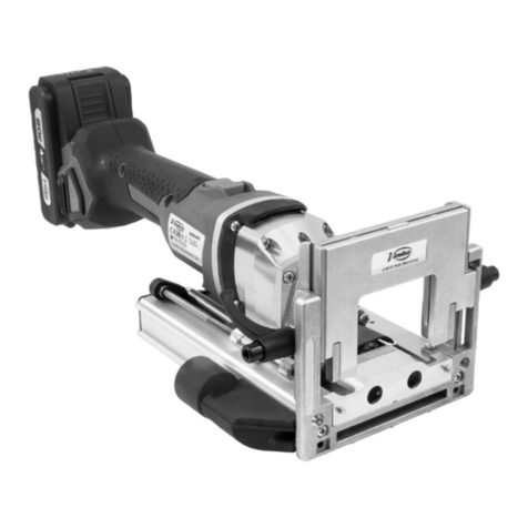
Virutex TWOO User manual

ABB400
MANUAL DE INSTRUCCIONES
OPERATING INSTRUCTIONS
MODE D’EMPLOI
GEBRAUCHSANWEISUNG
MANUALE D’ISTRUZIONI
MANUAL DE INSTRUÇÕES
ИНСТРУКЦИЯ ПО ЭКСПЛУАТАЦИИ
INSTRUKCJA OBSŁUGI
Espigadora TWOO a batería
Cordless Dowelling Jointer TWOO
Tourillonneuse TWOO à baerie
AKKU - Twin-Dübelbohrmaschine TWOO
Sistema di spinatura TWOO a baeria
Fresadora de Cavilhas TWOO a bateria
Аккумуляторный присадочный фрезер TWOO
Akumulatorowa Frezarka do połączeń kołkowych TWOO

8
donde adquirieron el producto, o con las autoridades
locales pernentes, para informarse sobre cómo y dónde
pueden llevarlo para que sea somedo a un reciclaje
ecológico y seguro.
VIRUTEX se reserva el derecho de modicar sus pro-
ductos sin previo aviso.
ENGLISH
ABB400 CORDLESS DOWELLING JOINTER TWOO
1. SAFETY INSTRUCTIONS
1.1 GENERAL SAFETY INSTRUCTIONS
Read these OPERATING INSTRUCTIONS.
Make sure you have understood them
before operang the machine for the
rst me.
Save all warnings and instrucons for future reference.
The term “power tool” in the warnings refers to the
power tool run o the electrical network (with a power
cord) or to a baery run power tool (cordless).
Read all instrucons. Failure to follow all
instrucons listed below may result in
electric shock, re and/or serious injury.
The term “power tool” in all of the warnings
listed below refers to your mains operated
(corded) power tool or baery operated
(cordless) power tool.
1) Work area
a) Keep work area clean and well lit. Cluered and dark
areas invite accidents.
b) Do not operate power tools in explosive atmospheres,
such as in the presence of ammable liquids, gases or
dust. Power tools create sparks which may ignite the
dust or fumes.
c) Keep children and bystanders away while operang a
power tool. Distracons can cause you to lose control.
d) Never leave the power tool unaended. Leave the
machine only when the tool is completely in neutral.
2) Electrical safety
a) Power tool plugs must match the outlet. Never mo-
dify the plug in any way. Do not use any adapter plugs
with earthed (grounded) power tools. Unmodied plugs
and matching outlets will reduce risk of electric shock.
b) Avoid body contact with earthed or grounded sur-
faces such as pipes, radiators, ranges and refrigerators.
There is an increased risk of electric shock if your body
is earthed or grounded.
c) Do not expose power tools to rain or wet condions.
Water entering a power tool will increase the risk of
electric shock.
d) Do not abuse the cord. Never use the cord for carrying,
pulling or unplugging the power tool. Keep cord away
from heat, oil, sharp edges or moving parts. Damaged
or entangled cords increase the risk of electric shock.
e) When operang a power tool outdoors, use an exten-
sion cord suitable for outdoor use. Use of a cord suitable
for outdoor use reduces the risk of electric shock.
f) If operang a power tool in a damp locaon is una-
voidable, use a residual current device (RCD) protected
supply. Use of an RCD reduces the risk of electric shock.
3) Personal safety
a) Stay alert, watch what you are doing and use com-
mon sense when operang a power tool. Do not use a
power tool while you are red or under the inuence
of drugs, alcohol or medicaon. A moment of inaen-
on while operang power tools may result in serious
personal injury.
b) Use safety equipment. Always wear eye protecon.
Safety equipment such as dust mask, non-skid safety
shoes, hard hat, or hearing protecon used for appro-
priate condions will reduce personal injuries.
c) Avoid accidental starng. Ensure the switch is in the
o posion before plugging in. Carrying power tools
with your nger on the switch or plugging in power
tools that have the switch on invites accidents.
d) Remove any adjusng key or wrench before turning
the power tool on. A wrench or a key le aached
to a rotang part of the power tool may result in
personal injury.
e) Do not overreach. Keep proper foong and balance
at all mes. This enables beer control of the power
tool in unexpected situaons.
f) Dress properly. Do not wear loose clothing or jewe-
llery. Keep your hair, clothing and gloves away from
moving parts. Loose clothes, jewellery or long hair can
be caught in moving parts.
g) If devices are provided for the connecon of dust
extracon and collecon facilies, ensure these are
connected and properly used. Use of these devices
can reduce dust related hazards.
h) Do not allow the familiarity with the frequent use of
tools to become complacent and ignore the principles
of tool safety. Negligence can cause serious injury in
a split second.
4) Power tool use and care
a) Do not force the power tool. Use the correct power
tool for your applicaon. The correct power tool will
do the job beer and safer at the rate for which it
was designed.
b) Do not use the power tool if the switch does not turn

9
mechanism safeguards the user against fragments of
broken bits and from accidental contact with the bit.
4. WHEN REPLACING THE BLADE, USE ONLY ORI-
GINAL VIRUTEX BLADES. Never use blades which do
not comply with the properes specied in this manual.
Do not use malformed or broken blades. Do not use
high-speed steel.
The assigned speed of the blade must be at least equal
to that marked on the machine: Blades that work at a
faster speed than the assigned speed may be parally
thrown out, causing injury.
5. AVOID CUTTING NAILS AND KNOTS. Inspect the
wood and remove nails before cung. Try not to cut
through knots.
6. Hold the machine by the insulated gripping surfaces,
as the blade may touch the machine’s power cable:
Cung an electried cable may also electrify the ac-
cessible metal parts of the machine and cause electric
shock to the user.
Unplug the machine from the baery
outlet before any maintenance operaons.
1.3 SAFETY INSTRUCTIONS FOR USE AND MAIN-
TENANCE OF THE BATTERY AND CHARGER
Do not store the tool and baery cartridge
in locaons where the temperature may
reach or exceed 45° C.
Do not incinerate the baery cartridge.
Do not expose baery cartridge to water
or rain.
• Only recharge with the manufacturer's specied
charger. Only recharge with the manufacturer's specied
charger. A charger which is suitable for one type of
baery cartridge can cause a re risk on another type
of baery cartridge.
• Only use this power tool with the baery cartridge
specically designed for this model. The use of other
types of baery cartridges may cause injury to the
operator and a re risk.
• When the baery cartridge is not in use, keep it away
from metal objects, such as paperclips, coins, keys, nails,
screws or other small metal objects that can establish
contact from one terminal to the other. Shorng the
baery terminals may cause burns or a re.
• Baery uid may be spilled under extreme condions;
it on and o. Any power tool that cannot be controlled
with the switch is dangerous and must be repaired.
c) Disconnect the plug from the power source before
making any adjustments, changing accessories, or
storing power tools. Such prevenve safety measures
reduce the risk of starng the power tool accidentally.
d) Store idle power tools out of the reach of children
and do not allow persons unfamiliar with the power tool
or these instrucons to operate the power tool. Power
tools are dangerous in the hands of untrained users.
e) Maintain power tools. Check for misalignment or
binding of moving parts, breakage of parts and any other
condion that may aect the power tools operaon. If
damaged, have the power tool repaired before use. Many
accidents are caused by poorly maintained power tools.
f) Keep cung tools sharp and clean. Properly main-
tained cung tools with sharp cung edges are less
likely to bind and are easier to control.
g) Use the power tool, accessories and tool bits etc., in
accordance with these instrucons and in the manner
intended for the parcular type of power tool, taking
into account the working condions and the work to
be performed. Use of the power tool for operaons
dierent from those intended could result in a hazar-
dous situaon.
h) Keep the handles dry, clean and free of oil and grease.
The sliding handles do not allowsafe handling and control
of the tool in unexpected situaons. Power tools with
the switch on invite these situaons.
5) Service
a) Have your power tool serviced by a qualied repair
person using only idencal replacement parts. This will
ensure that the safety of the power tool is maintained.
b) Use only original parts for repair and maintenance.
The use of incompable accessories and parts can cause
electric shock and other injuries.
1.2 SAFETY INSTRUCTIONS FOR
THE JOINTING MACHINE USE
Carefully read the GENERAL SAFETY
INSTRUCTION LEAFLET enclosed with
the machine documents.
1. Supply voltage must be the same as that indicated
on the specicaons plate.
2. DANGER: KEEP HANDS AWAY FROM THE CUTTING
ZONE. Never put hands near the cung blade. Do not
hold the underside of the machine when it is operang.
3. Ensure that the safety mechanism (retracon)
funcons freely without any danger of being held
back. Do not block the mechanism with the blade in
the exposed posion.
Always use the protecve mechanism: The protecve

10
avoid contact with this liquid. In case of accidental
contact, rinse thoroughlywith water. If the liquid comes
into contact with your eyes, seek medical aenon.
Baery uid may cause irritaon or burns.
• Do not use damaged or modied baeries. Damaged
or modied baeries can behave in an unpredictable
way and may cause injury to the operator and a re risk.
• Avoid switching the device on accidentally. Make sure
the on/o switch is in the o posion before inserng
the baery. Carrying the power tool with your nger
on the on/o switch or inserng the baery with the
switch in the on posion can cause accidents.
• Do not open the baeries. You could damage the
circuits.
• Fumes may be aired if there is baery damage and
improper use. In this case, go to a well-venlated locaon
and seek medical assistance, if necessary. Fumes cause
respiratory irritaon.
• When the baery is defecve, the liquid may leak and
come into contactwith adjacent components. Check the
corresponding parts. Clean or replace them, if necessary.
• Protect the baery from heat, connued solar radiaon
and re. There is an explosion hazard.
Read all instrucons and safety warnings.
• Protect the baery charger from rain and moisture.
Water entering the charger increases the risk of electric
shock.
• Do not charge other baeries. The baery charger is
only suitable for charging lithium-ion baeries within
the indicated voltage range. Otherwise, there is a re
and explosion hazard.
• Keep the baery charger clean. Dirt can cause a risk
of electric shock.
• Always check the baery charger, its cable and plug
before using them. Do not use the charger if you see
it is damaged. Do not open the charger on your own.
Have it repaired by a qualied person who uses original
spare parts. Damaged chargers, cables and plugs increase
the risk of electric shocks.
• Do not use the baery charger on highly ammable
surfaces. For example, paper, texles, etc., or in
combusble environments. A re hazard exists from
the charger heang during the charging cycle.
2. SPECIFICATIONS
Baery voltage........................................................20 V
No-load speed...............................................7,000 min
-1
Baery type.…................................................................Li-Ion
Time to charge baery.…................................60 min
Baery capacity.....................................................2 or 4 A
h
Disc.....................................................D100xD22x4mm
Roung depth.................................................…..20 mm
Weight...........................................................................3 kg
Weighted equivalent connuous acousc
pressure level A.............................................................92 dBA
Acousc power level A...............................................103 dBA
Uncertainty................................................................K: 3 dBA
Wear ear protecon!
Vibraon total values.........................................a
h
: 4,7 m/s
2
Uncertainty..........................................................K: 1,5 m/s
2
3. SPECIFICATIONS OF THE TOOL
Brushless motor
Power tool equipped with a brushless motor that pro-
vides the following advantages (compared to the power
tool having a brush motor):
• High reliability due to the lack of wearing parts (car-
bon brushes, commutator).
• Increased operang me on a single charge.
• Compact design and light weight.
Temperature protecon
The temperature protecon system enables to auto-
macally deacvate the power tool in case of excess
load or when the temperature of the baery 7 (Fig. 1)
is exceeding 70°C. The system guarantees protecon of
the power tool from damage in case of noncompliance
with the operaon condions.
Overdischarge protecon
The baery 7 (Fig. 1) is protected by the safety system
against deep discharge. In case of complete discharge,
the power tool is automacally switched o.
Do not try to switch on the power tool
when the protecon system is acvated
the baery 7 (Fig. 1) can be damaged.
Indicators of the state of baery charge
With the push of the buon 6 the indicators 5 show
the state of charge of the baery 7.
Overheang protecon
Overheang protecon system of the engine automa-
cally switches o the power tool in case of overheang.
In this situaon, let the tool cool before turning the
power tool on again.
Overload protecon
Overload protecon system of the engine automacally
switches o the power tool when it is operated in a man-
ner that causes it to draw an abnormally high current.
So start
So start enables smooth start of power tools - is

11
being run up gradually with no jerks and kickbacks; no
jump-like load is imposed on the motor upon switching.
4. HOW TO CHARGE THE BATTERY
Baery charging me
Inial operang of the power tool
Before the rst use, the baery 7 (Fig. 1) must be
fully charged.
Charging process (Fig. 2)
• Press the baery lock 4 and remove the baery 7
(Fig. 1).
• Connect the charger 19 to the power supply.
• Insert baery 7 into charger 19 (Fig. 2).
• Disconnect the charger 19 from power supply aer
charging.
• Remove the baery 7 from the charger 19 and mount
baery 7 in the power tool.
Charger indicators (Fig. 3)
Charger indicators 21 and 22 inform of the baery 7
(Fig. 1) charging process. Signals of the indicators 21
and 22 are shown on the label 20. (Fig. 3).
• Fig. 40.1 - (The green indicator 22 is on, the baery
7 is not inserted in the charger 19) - the charger 19 is
connected to the power network (ready for charging).
• Fig. 40.2 - (The green indicator 22 is blinking, the
baery 7 is inserted in the charger 19) - the baery 7
is being charged.
• Fig. 40.3 - (The green indicator 22 is on, the baery
7 is inserted in the charger 19) - the baery 7 is fully
charged.
• Fig. 40.4 - (The red indicator 21 is on, the baery
7 is inserted in the charger 19) - the charging process
of the baery 7 is terminated due to inappropriate
temperature. When the temperature condions are
normal, the process of charging will resume.
• Fig. 40.5 - (The red indicator 21 is blinking, the baery
7 is inserted in the charger 19) - the charging process
of the baery 7 is terminated because of its failure.
Replace the faulty baery 7, its further use is prohibited.
In the process of charging the baery 7 and the charger
19 become hot, it is a normal process.
5. STARTING UP THE MACHINE
To start up the machine, push buon forward to the
on posion.
To stop the machine, simply press the back of the switch
and it will return to the o posion.
6. NOISE LEVEL AND VIBRATIONS
The noise and vibraon levels of this device have
been measured in accordance with European stan-
dard EN 60745-2-19 and EN 60745-1 and serve as a
basis for comparison with other machines with similar
applicaons.
The indicated vibraon level has been determined
for the device’s main applicaons and may be used
as an inial value for evaluang the risk presented by
exposure to vibraons. However, vibraons may reach
levels that are quite dierent from the declared value
under other applicaon condions, with other tools or
with insucient maintenance of the electrical device
or its accessories, reaching a much higher value as a
result of the work cycle or the manner in which the
electrical device is used.
Therefore, it is necessary to establish safety measures
to protect the user from the eects of vibraons, such
as maintaining both the device and its tools in perfect
condion and organising the duraon of work cycles
(such as operang mes when the machine is subjected
to loads, and operang mes when working with no-load,
in eect, not in use, as reducing the laer may have a
considerable eect upon the overall exposure value).
7. WARRANTY
All VIRUTEX power tools are guaranteed for 12 months
from the date of purchase, excluding any damage which
is a result of incorrect use or of natural and tear on the
machine. All repairs should be carried out by the ocial
VIRUTEX technical assistance service.
8. RECYCLING ELECTRICAL EQUIPMENT
Never dispose of electrical equipment with domesc
waste. Recycle equipment, accessories and packaging
in ways that minimise any adverse eect on the envi-
ronment. Comply with the current regulaons in your
country.
Applicable in the European Union and in European
countries with selecve waste collecon systems:
If this symbol appears on the product or in the accom-
panying informaon, at the end of the product's useful
life it must not be disposed of with other domesc waste.
In accordance with European Direcve 2002/96/EC,
users may contact the establishment where they pur-
chased the product or the relevant local authority to
nd out where and how they can take the product for
environmentally friendly and safe recycling.
VIRUTEX reserves the right to modify its products
without prior noce.
41
Fresado a 90º (Tabla)
Drilling at 90º (Table)
Fraisage à 90º (Tableau)
Bohren im 90°-Winkel (Tabelle)
Fresatura a 90º (Tabella)
Fresagem 90º (Tabela)
Сверление под углом 90º (Таблица)
Wiercenie pod kątem 90º (Tabela)
Galga de grosor del panel
Panel thickness gauge
Jauge d'épaisseur de panneau
Plaendickenmessgerät
Spessimetro per pannelli
Medidor de espessura do painel
Измеритель толщины панели
Wskaźnik grubości panelu
=
=
A
B
B
6x20
mm
6x25
mm
6x30
mm
8x25
mm
8x30
mm
8x40
mm
10x40
mm
12x40
mm
15 mm • •
16 mm • •
18 mm •••••
19 mm •••••
22 mm • •
25 mm •••••
30 mm •••••
40 mm •••••
B
A

42
Fresado a 45º (Tabla)
Drilling at 45º (Table)
Fraisage à 45º (Tableau)
Bohren im 45°-Winkel (Tabelle)
Fresatura a 45º (Tabella)
Fresagem 45º (Tabela)
Сверление под углом 45º (Таблица)
Wiercenie pod kątem 45º (Tabela)
6x20 6x25 6x30 8x25 8x30 8x40 10x40 12x40
15 mm •
16 mm •
18 mm • • •
19 mm ••••
22 mm • •
25 mm •••••
30 mm •••••
40 mm •••••
B
A
Grosor del panel · Panel thickness
Épaisseur du panneau · Plaendicke
Spessore del pannello
Espessura do painel · Толщина панели
Grubość panelu
(*) Opcional | Oponal
En opon | Опционально
Opcjonalny
7940101 – Ø 5*
7940103 – Ø 6
7940105 – Ø 8
7940107 – Ø 10
7940109 – Ø 12
Fresa MD
Bit HM
Fraise MD
Hartmetall Bohrer
Fresa MD
Fresa MD
карбидный резак
Frez z węglików spiekanych

43
6x20 6x25 6x30 8x25 8x30 8x40 10x40 12x40
15 mm •
16 mm •
18 mm • • •
19 mm ••••
22 mm • •
25 mm •••••
30 mm •••••
40 mm •••••
Fresado a 90º
Drilling at 90º
Fraisage à 90º
Bohren im 90°-Winkel
Fresatura a 90º
Fresagem 90º
Сверление под углом 90º
Wiercenie pod kątem 90º
Ajuste de la profundidad de fresado
Drilling depth adjustment
Réglage de la profondeur du fraisage
Einstellen der fräsefe
Regolazione della profondità di fresatura
Ajuste de profundidade de fresagem
Настройка глубины фрезерования
Regulacja głębokości frezowania
32 mm
B
B
25 mm

44
Regulación de la altura de fresado (con galga)
Drilling height adjustment (with gauge)
Réglage de la hauteur de fraisage (avec jauge)
Bohrefeneinstellung (Fühllehre)
Regolazione dell'altezza di fresatura (con calibro)
Ajuste de altura de fresagem (com medidor)
Регулировка высоты фрезерования (с использованием шаблона)
Regulacja wysokości frezowania (z wykorzystaniem wzornika)
=
=

45
Posicionamiento de la máquina para el fresado
(sendo horizontal)
Posioning of the machine for drilling
(horizontal direcon)
Posionnement de la machine pour le fraisage
(sens horizontal)
Posionieren der Maschine für horizontale Bo-
hrungen
Posizionamento della macchina per la fresatura
(direzione orizzontale)
Posicionamento da máquina para fresagem (di-
reção horizontal)
Позиционирование присадочного шпинделя (в
горизонтальном направлении)
Pozycjonowanie maszyny do frezowania (kierunek
poziomy)

46
Posicionamiento de la máquina para el fresado (sendo vercal)
Posioning of the machine for drilling (vercal direcon)
Posionnement de la machine pour le fraisage (sens vercale)
Posionieren der Maschine für verkale Bohrungen
Posizionamento della macchina per la fresatura (direzione vercale)
Posicionamento da máquina para fresagem (direção vercal)
Позиционирование присадочного шпинделя (в вертикальном направлении)
Pozycjonowanie maszyny do frezowania (kierunek pionowy)

47
Fresado a 45º
Drilling at 45º
Fraisage à 45º
Bohren im 45°-Winkel
Fresatura a 45º
Fresagem 45º
Сверление под углом 45º
Wiercenie pod kątem 45º

48
Cambio de fresas
Changing the bits
Changement de les fraises
Auswechseln der fräsen
Cambio de fresi
Substuição de fresas
Замена режущего инструмента
Wymiana frezów

49
Fresado con accesorio multaladro (lado izquierdo)
Drilling with mul-hole accessory (le side)
Fraisage avec accessoire mul-trous (côté gauche)
Bohren mit Mehrfachbohranschlag -Zubehör- (Linke Seite)
Fresatura con accessorio mulforo (lato sinistro)
Fresamento com acessório mulfuros (lado esquerdo)
Сверление с приспособлением для сверления нескольких отверстий (с левой стороны)
Frezowanie z wielowiertłem (strona lewa)
16

50
Fresado con accesorio multaladro (lado derecho)
Drilling with mul-hole accessory (right side)
Fraisage avec accessoire mul-trous (côté droit)
Bohren mit Mehrfachbohranschlag -Zubehör- (Rechte Seite)
Fresatura con accessorio mulforo (lato destro)
Fresamento com acessório mulfuros (lado direito)
Сверление с приспособлением для сверления нескольких отверстий (с правой стороны)
Frezowanie z wielowiertłem (strona prawa)
Inverr la posición del accesorio
Reverse accessory posion
Inverser la posion des accessoires
Umkehren der Bohrposion
Posizione inversa dell'accessorio
Posição inverda do acessório
Реверс вспомогательного шпинделя
Odwróć pozycję akcesorium

51
Fresado con tope longitudinal
Drilling with longitudinal stopper
Fraisage avec butée longitudinale
Bohren mit Längenanschlag
Fresatura con bauta longitudinale
Fresamento com batente longitudinal
Ограничитель глубины сверления
Wiercenie z zatrzymywaczem podłużnym
10, 20, 30, 40... 15, 25, 35, 45...

52
16

53
Fresado con accesorio para colocar baldas intermedias
Drilling with accessory to place intermediate shelves
Fraisage avec accessoire pour placer des étagères intermédiaires
Bohren mit Zubehör für Zwischenböden
Fresatura con accessorio per posizionamento ripiani intermedi
Fresagem com acessório para colocação de prateleiras intermediárias
Насадка для сверления под съемные полки
Wiercenie z akcesoriami do umieszczania półek pośrednich

54

55
Fresado en el centro del tablero
Drilling in the middle of the panel
Fraisage au centre du panneau
Bohren in der Mie des Panels
Fresatura al centro del pannello
Fresagem no centro do painel
Фрезерование в центре панели
Wiercenie w środku panelu
Other manuals for TWOO
1
Table of contents
Other Virutex Power Tools manuals

Virutex
Virutex RM95S User manual

Virutex
Virutex AG98E User manual

Virutex
Virutex CR94D User manual

Virutex
Virutex TWOO AB200 User manual

Virutex
Virutex SVN450 User manual

Virutex
Virutex FR66P User manual

Virutex
Virutex AB111N User manual

Virutex
Virutex MEB250A User manual

Virutex
Virutex TWOO AB200 User manual

Virutex
Virutex AB181 User manual

Virutex
Virutex CE35E User manual

Virutex
Virutex ABB311 User manual

Virutex
Virutex FR817T User manual

Virutex
Virutex FR278R User manual

Virutex
Virutex AG98R User manual

Virutex
Virutex AB11C User manual

Virutex
Virutex RZ270S User manual

Virutex
Virutex FRE160P User manual

Virutex
Virutex EM25D User manual

Virutex
Virutex FC16S User manual