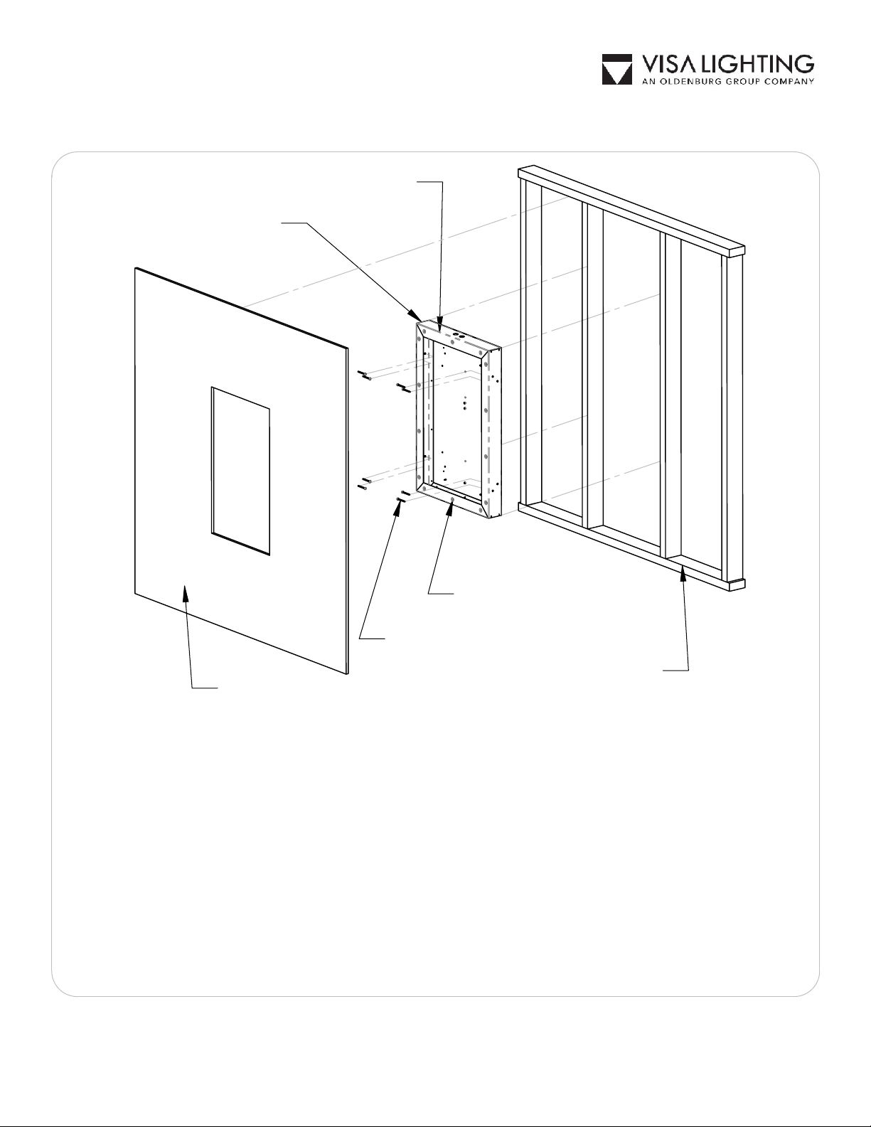
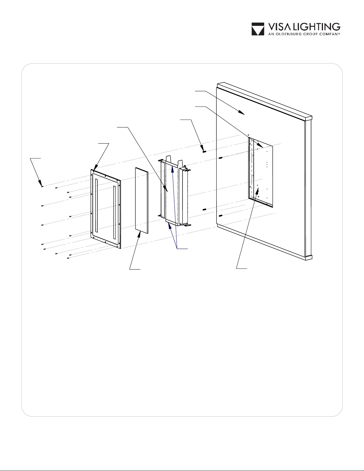
Visa Lighting Sole Series User manual

CB1850 - RECTANGULAR
PAGE 2, 3, and 4
SOLE
CB1852 - OVAL
PAGE 5, 6, and 7
Drawing:
762277XX
Rev:
F
Sheet:
1 of 9
Eng:
CG2
Date Drawn:
10/27/19
INSTALLATION INSTRUCTIONS
Model:
CB1850, CB1852
Fixture Family:
SOLE
1717 West Civic Drive Milwaukee, WI 53209
414-354-6600
Design Modification Rights Reserved
© Visa Lighting 2016
!
When using electrical equipment, basic safety precautions should always be followed, including the following:
Read all instructions carefully before installing and save for future use.
•
Make sure all connections are in accordance with the National Electrical Code and local regulations.
•
To avoid possible electric shock, be sure the power supply is turned off before servicing or installing the fixture
•
Service should be performed by qualified personnel.
•
These instructions may not cover all details or variations. If additional information is needed, please contact Visa Lighting.
•
Document Description: Installation Instructions for
Sole Series Mirrors

IMPORTANT SAFETY INSTRUCTIONS
Read all instructions before using this illuminated mirror.
WARNING:
* To reduce the risk of burns, fire, electric shock, or injury to persons:
* When using an electrical furnishing, basic precautions should always be followed, including
the following:
*Use this illuminated mirror for its intended use as described in these instructions. Do not
use attachments not recommended by the manufacturer.
WARNING:
* Risk of Death or Serious Injury
* Do not install near pools, ponds, or other bodies of water.
SAVE THESE INSTRUCTIONS
WARNING
:
To reduce risk of Ligature:
* Ensure all fasteners are fully seated and do not protrude from the mirror frame.
* Apply a pickproof sealant around the perimeter of the frame in the slight gap
between the frame and mounting substrate.
Drawing:
762277XX
Rev:
F
Sheet:
2 of 9
Eng:
CG2
Date Drawn:
10/27/19
INSTALLATION INSTRUCTIONS
Model:
CB1850, CB1852
Fixture Family:
SOLE
1717 West Civic Drive Milwaukee, WI 53209
414-354-6600
Design Modification Rights Reserved
© Visa Lighting
!
When using electrical equipment, basic safety precautions should always be followed, including the following:
Read all instructions carefully before installing and save for future use.
•
Make sure all connections are in accordance with the National Electrical Code and local regulations.
•
To avoid possible electric shock, be sure the power supply is turned off before servicing or installing the fixture
•
Service should be performed by qualified personnel.
•
These instructions may not cover all details or variations. If additional information is needed, please contact Visa Lighting.
•
Document Description: Installation Instructions for
Sole Series Mirrors

CLEANING AND CARE INSTRUCTIONS
Use care when cleaning this LED Luminaire. The mirror is made of polycarbonate. Do not use
abrasive cleaners, chemicals or solvents which may result in surface damage to lens or housing.
The luminaire can be cleaned by hose-directed water spray to remove any dust or debris. If
necessary, use mild soap with warm water for cleaning the exterior surfaces of this fixture.
This product must be connected to a grounded metal, permanent wiring system, or an
equipment grounding conductor must be run with the circuit conductors and connected to the
equipment grounding terminal or lead on the product. Electrical Ratings: 120-277 VAC,
50/60Hz, 50 W MAX
GROUNDING INSTRUCTIONS
SAVE THESE INSTRUCTIONS
IMPORTANT SAFETY INSTRUCTIONS
Read all instructions before using this illuminated mirror.
Drawing:
762277XX
Rev:
F
Sheet:
3 of 9
Eng:
CG2
Date Drawn:
10/27/19
INSTALLATION INSTRUCTIONS
Model:
CB1850, CB1852
Fixture Family:
SOLE
1717 West Civic Drive Milwaukee, WI 53209
414-354-6600
Design Modification Rights Reserved
© Visa Lighting
!
When using electrical equipment, basic safety precautions should always be followed, including the following:
Read all instructions carefully before installing and save for future use.
•
Make sure all connections are in accordance with the National Electrical Code and local regulations.
•
To avoid possible electric shock, be sure the power supply is turned off before servicing or installing the fixture
•
Service should be performed by qualified personnel.
•
These instructions may not cover all details or variations. If additional information is needed, please contact Visa Lighting.
•
Document Description: Installation Instructions for
Sole Series Mirrors

WALLBOARD/DRYWALL (see page 5 for dimensions)
INSERT NUTS
FIXTURE HOUSING
(to be recessed)
WALL STUDS
(see page 5 for
dimensions)
FLANGE
MOUNTING SCREWS (8)
NOTE: FOR INSTALLATIONS IN A FIRE RATED LOCATION, INSTALL PER LOCAL
AND STANDARD CODE.
Remove LED assembly (see page 4) from fixture and store until wallboard is installed
1.
and finished. Reinstall (4) standoffs (see page 4) into recessed fixture housing for
future use.
Install recessed fixture housing, secure fixture housing to studs or appropriate stable
2.
structure. Fixture housing face should be flush with back side of the wallboard.
Route line voltage and dimming wires (if needed), and finish wall. NOTE: Wallboard to
3.
be no more than 1" thick. If thicker wall board is required, consult factory.
Cut wallboard even with the inside profile of the installed recessed fixture housing. Do
4.
not remove the wallboard over the flanges of the fixture housing.
Set aside wallboard for support piece in step 3 on page 5.
5.
Drawing:
762277XX
Rev:
F
Sheet:
4 of 9
Eng:
CG2
Date Drawn:
10/27/19
INSTALLATION INSTRUCTIONS
Model:
CB1850, CB1852
Fixture Family:
SOLE
1717 West Civic Drive Milwaukee, WI 53209
414-354-6600
Design Modification Rights Reserved
© Visa Lighting
!
When using electrical equipment, basic safety precautions should always be followed, including the following:
Read all instructions carefully before installing and save for future use.
•
Make sure all connections are in accordance with the National Electrical Code and local regulations.
•
To avoid possible electric shock, be sure the power supply is turned off before servicing or installing the fixture
•
Service should be performed by qualified personnel.
•
These instructions may not cover all details or variations. If additional information is needed, please contact Visa Lighting.
•
Document Description: Installation Instructions for
Sole Series Mirrors

LENS FRAME ASSEMBLY
LED ASSEMBLY
MOUNTING SURFACE
RECESSED FIXTURE HOUSING
NOTE: FOR INSTALLATIONS IN A FIRE RATED LOCATION, INSTALL PER LOCAL
AND STANDARD CODE.
STANDOFFS (4)
CENTER DRYWALL
SUPPORT (insert piece)
TORX SCREW (14)
(See Note C on
page 6)
WIRING COMPARTMENT
DOUBLE-SIDED
TAPE (2)
Locate the top and botttom middle insert nut (see page 4) inside the fixture housing. Using a 1/4"
1.
drill, open up a hole in the wallboard centered over the insert nut. Verify you have completely
removed the wallboard by starting a lens screw into the inserted nuts. Once the top and bottom
middle insert nuts are accessible, attach the mirror/frame assembly to the recessed fixture
housing using two screws, hand tighten. Once fully seated, mark the remaining screw holes.
Remove and set aside the mirror/frame assembly and drill the remaining holes until the threaded
inserts are accessible.
Wire the LED assembly and reinstall into the recessed housing using nuts/standoffs.
2.
Using the saved wallboard cutout, cut an insert piece to fill in the area over the wiring
3.
compartment. Attach using the double-sided tape on the LED assembly.
Attach the mirror/frame assembly using the provided screws (14) .
4.
Apply pickproof caulk bead between wall and mirror around the entire perimeter of lens frame.
5.
Drawing:
762277XX
Rev:
F
Sheet:
5 of 9
Eng:
CG2
Date Drawn:
10/27/19
INSTALLATION INSTRUCTIONS
Model:
CB1850, CB1852
Fixture Family:
SOLE
1717 West Civic Drive Milwaukee, WI 53209
414-354-6600
Design Modification Rights Reserved
© Visa Lighting
!
When using electrical equipment, basic safety precautions should always be followed, including the following:
Read all instructions carefully before installing and save for future use.
•
Make sure all connections are in accordance with the National Electrical Code and local regulations.
•
To avoid possible electric shock, be sure the power supply is turned off before servicing or installing the fixture
•
Service should be performed by qualified personnel.
•
These instructions may not cover all details or variations. If additional information is needed, please contact Visa Lighting.
•
Document Description: Installation Instructions for
Sole Series Mirrors

20 21/32"
30 15/16"
16 1/2"
27"
DIMENSIONS OF ROUGH IN AND SHEETROCK CUT OUT FOR RECTANGULAR SOLE
NOTES:
A. Ingress protection for fixture is from the outside only. Sole is not sealed from wall cavity.
B. Wall gasket must be installed on a smooth flat surface (i.e. acrylic or vinyl for washdown
applications) for IP65 rating. Rough, textured, round, or otherwise curved surfaces require
additional sealing measures (not provided).
C. For IP rating the nylon screw sleeves must be used with the mounting screws.
D. Use microfiber cloth to clean mirrror.
Drawing:
762277XX
Rev:
F
Sheet:
6 of 9
Eng:
CG2
Date Drawn:
10/27/19
INSTALLATION INSTRUCTIONS
Model:
CB1850, CB1852
Fixture Family:
SOLE
1717 West Civic Drive Milwaukee, WI 53209
414-354-6600
Design Modification Rights Reserved
© Visa Lighting
!
When using electrical equipment, basic safety precautions should always be followed, including the following:
Read all instructions carefully before installing and save for future use.
•
Make sure all connections are in accordance with the National Electrical Code and local regulations.
•
To avoid possible electric shock, be sure the power supply is turned off before servicing or installing the fixture
•
Service should be performed by qualified personnel.
•
These instructions may not cover all details or variations. If additional information is needed, please contact Visa Lighting.
•
Document Description: Installation Instructions for
Sole Series Mirrors

WALL STUDS
(see page 5 for dimensions)
FIXTURE HOUSING
(to be recessed)
MOUNTING SCREWS (8)
WALL BOARD/DRYWALL (see page 9 for dimensions)
INSERT NUTS
NOTE: FOR INSTALLATIONS IN A FIRE RATED LOCATION, INSTALL PER LOCAL
AND STANDARD CODE.
Remove foam insert and LED assembly (see page 8) from fixture and store until wall board
1.
is installed and finished. Reinstall (4) nuts into fixture housing for future use.
Install fixture housing, secure fixture housing to studs or appropriate stable structure.
2.
Recessed fixture housing face should be flush with back side of the wall board.
Route line voltage and dimming wires (if needed), and finish wall. NOTE: Wallboard to be no
3.
more than 1" thick. If thicker wall board is required, consult factory.
Cut wallboard even with the inside profile of the installed recessed fixture housing. Do not
4.
remove the wallboard over the fixture housing.
Drawing:
762277XX
Rev:
F
Sheet:
7 of 9
Eng:
CG2
Date Drawn:
10/27/19
INSTALLATION INSTRUCTIONS
Model:
CB1850, CB1852
Fixture Family:
SOLE
1717 West Civic Drive Milwaukee, WI 53209
414-354-6600
Design Modification Rights Reserved
© Visa Lighting
!
When using electrical equipment, basic safety precautions should always be followed, including the following:
Read all instructions carefully before installing and save for future use.
•
Make sure all connections are in accordance with the National Electrical Code and local regulations.
•
To avoid possible electric shock, be sure the power supply is turned off before servicing or installing the fixture
•
Service should be performed by qualified personnel.
•
These instructions may not cover all details or variations. If additional information is needed, please contact Visa Lighting.
•
Document Description: Installation Instructions for
Sole Series Mirrors

TORX SCREWS (10)
(See Note C on page 9)
LENS ASSEMBLY
MOUNTING SURFACE
FOAM INSERT (2)
*IMPORTANT*
CENTER DRWALL
SUPPORT
DOUBLE-SIDED
TAPE (2)
WIIRING COMPARTMENT
LED ASSEMBLY
Locate the right and left middle top insert nut inside the fixture housing (see page 7). Using a 1/4"
1.
drill, open up a hole in the wallboard centered over the insert nut. Verify you have completely
removed the wallboard by starting a lens screw into the insert nuts. Once the top and bottom
middle insert nuts are accessible, attach the mirror/frame assembly to the recessed fixture housing
using two screws hand tightened. Once fully seated, mark the remaining screw holes. Remove
and set aside the mirror/frame assembly and drill the remaining holes until the threaded inserts are
accessible.
Wire the LED assembly and reinstall into the recessed fixture housing using nuts/standoffs.
2.
Replace foam inserts.
3.
Using the same wallboard, cut an insert piece to fill in the area over the wiring compartment.
4.
Attach using the double-sided tape on the LED assembly.
Attach the mirror/frame assembly using the provided screws (10).
5.
Apply pickproof caulk bead between wall and mirror around the entire perimeter of lens frame.
6.
NOTE: FOR INSTALLATIONS IN A FIRE RATED LOCATION, INSTALL PER LOCAL
AND STANDARD CODE.
Drawing:
762277XX
Rev:
F
Sheet:
8 of 9
Eng:
CG2
Date Drawn:
10/27/19
INSTALLATION INSTRUCTIONS
Model:
CB1850, CB1852
Fixture Family:
SOLE
1717 West Civic Drive Milwaukee, WI 53209
414-354-6600
Design Modification Rights Reserved
© Visa Lighting
!
When using electrical equipment, basic safety precautions should always be followed, including the following:
Read all instructions carefully before installing and save for future use.
•
Make sure all connections are in accordance with the National Electrical Code and local regulations.
•
To avoid possible electric shock, be sure the power supply is turned off before servicing or installing the fixture
•
Service should be performed by qualified personnel.
•
These instructions may not cover all details or variations. If additional information is needed, please contact Visa Lighting.
•
Document Description: Installation Instructions for
Sole Series Mirrors

32"
10 3/4" 24 5/8"
18 3/4"
17 1/2"
11 3/4"
23 21/32"
DIMENSIONS OF ROUGH IN AND SHEETROCK CUT OUT FOR OVAL SOLE
NOTES:
A. Ingress protection for fixture is from the outside only. Sole is not sealed from wall cavity.
B. Wall gasket must be installed on a smooth flat surface (i.e. acrylic or vinyl for washdown
applications) for IP65 rating. Rough, textured, round, or otherwise curved surfaces require
additional sealing measures (not provided).
C. For IP rating the nylon screw sleeves must be used with the mounting screws.
D. Use microfiber cloth to clean mirrror.
Drawing:
762277XX
Rev:
F
Sheet:
9 of 9
Eng:
CG2
Date Drawn:
10/27/19
INSTALLATION INSTRUCTIONS
Model:
CB1850, CB1852
Fixture Family:
SOLE
1717 West Civic Drive Milwaukee, WI 53209
414-354-6600
Design Modification Rights Reserved
© Visa Lighting
!
When using electrical equipment, basic safety precautions should always be followed, including the following:
Read all instructions carefully before installing and save for future use.
•
Make sure all connections are in accordance with the National Electrical Code and local regulations.
•
To avoid possible electric shock, be sure the power supply is turned off before servicing or installing the fixture
•
Service should be performed by qualified personnel.
•
These instructions may not cover all details or variations. If additional information is needed, please contact Visa Lighting.
•
Document Description: Installation Instructions for
Sole Series Mirrors
This manual suits for next models
2
Table of contents
Other Visa Lighting Lighting Equipment manuals