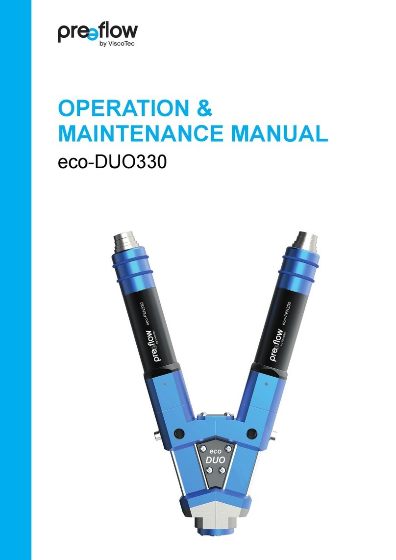
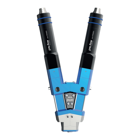
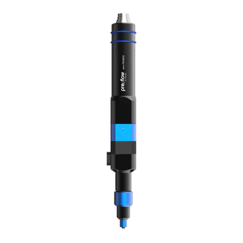
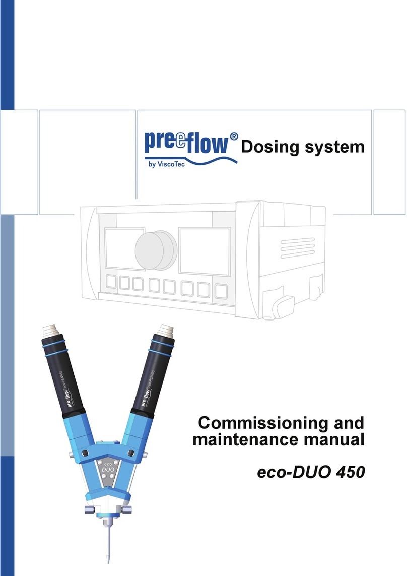
ViscoTec Preeflow eco-DUO600 Guide

Dosiersystem
Commissioning and
Maintenance Instructions
eco-DUO600


eco-DUO600
Commissioning and Maintenance Manual
Copyright © Version 1.4 3 / 23
Table of contents
1This manual 4
2The dispenser 4
3Safety 4
4Starting up for the first time 5
4.1 Connecting the dosing units to the drive units 5
4.2 Connecting sensors for monitoring dosing pressure 6
4.3 Supplying and bleeding the medium. 7
4.4 Calibration 8
4.5 Recommendations for problem-free operation 9
4.6 Cleaning the outlets 10
5Cleaning 11
5.1 Preparation 11
5.1.1 Separating the dispensers 11
5.1.2 Dismantling the dispenser 14
5.2 Assembly 16
6Spare parts 18
7Servicing 20
7.1 Changing the stator 20
7.2 Troubleshooting 20
8Technical specifications 21
9Disposal 22

eco-DUO600
Commissioning and Maintenance Manual
4 / 23 Version 1.4 Copyright ©
1This manual
Dear customer,
This manual forms part of the operating and maintenance manual for the dosing system
eco-CONTROL DUO. The operating and maintenance manual must have been read and
understood in full before commissioning or carrying out maintenance work on the eco-
DUO 600.
2The dispenser
The dispenser is supplied with these components and accessories:
• eco-DUO 600
• 2 Stators
• 2 drive units (without Fig.)
• Assembly aid
• 2 screwdrivers
• 2 Allen wrenches
• Calibration adapter
• Attachment plates (2 x)
• Mixer set (3 static mixers)
• Commissioning and maintenance manual
3Safety
All instructions in the Safety section of the
maintenance and operating manual for the
dosing system must be complied with and implemented.
Fig. 1

eco-DUO600
Commissioning and Maintenance Manual
Copyright © Version 1.4 5 / 23
4Starting up for the first time
Assembly Stators as follows:
• Disassembly dispensing unit as follows:
- 5.1.1, Separating the dispensers
- 5.1.2, Dismantling the dispenser
• Assembley Stators, see 5.2, Assembly
4.1 Connecting the dosing units to the drive units
• Turn the set screws (21) in the thread such that they do not protrude into the coupling
area. Danger of damage to the fit.
• Attach the star-shaped couplings (22) onto the coupling of the drive units (A).
• Couple the drive units (A) to the dosing units until a gap of <1mm is achieved between
the anti-rotation lock (23) and the dosing units.
• Position the anti-rotation lock correctly by turning the dosing units.
• Bring the drive units and dosing units together completely.
Do not switch on 2K dispenser until medium has been delivered to it. Otherwise there is
a risk of damage to the equipment. Even a brief period of dry running can lead to the
stator being destroyed.
A
21
21
23
22
Fig. 2

eco-DUO600
Commissioning and Maintenance Manual
6 / 23 Version 1.4 Copyright ©
4.2 Connecting sensors for monitoring dosing pressure
Attention:
The sensor cables must not be drilled during assembly!
Connect both sensors to the flowscreen analysis system*
* According to the instructions provided.

eco-DUO600
Commissioning and Maintenance Manual
Copyright © Version 1.4 7 / 23
4.3 Supplying and bleeding the medium.
• Connect the tank (supply line, cartridge) of the media to
both dispenser medium inputs (B).
(See section 8, Technical specifications, page 21 for
details of the thread)
• Bring the eco-DUO 600 into vertical position.
• Position the static mixing pipe (24) and lock in place.
For each dispenser:
• Connect the eco-DUO 600 to the power supply and
convey the medium until it comes out of the static mixing
pipe free from bubbles*.
Tip: Connecting a hose to the mixing pipe can protect the
eco-DUO 600 from being wetted with the medium.
• Unscrew the air bleed screw (27) with washer (28) to
bleed. Wipe off leaking medium with a cloth.
Tip: Never use the same cloth for both mediums. It would
cause a reaction between the components.
• Tighten the air bleed screw again.
* When filling for the first time, the blocking medium is first
removed from inside the dispenser (stator).
Follow the safety stipulations and instructions of the manufacturer of the medium
to be used to fill the unit. If applicable, use the required protective equipment. If
the medium is being conveyed for the first time, there is a danger from medium
spurting out. Air bubbles can cause uncontrollable spurting out. Ensure that you stand
back a safe distance.
24
27
28
B
Fig. 3

eco-DUO600
Commissioning and Maintenance Manual
8 / 23 Version 1.4 Copyright ©
4.4 Calibration
A calibration adapter is available for calibrating the eco-DUO 600. It is mounted on the
outlets. The eco-Control EC 200-DUO calibration programmes can be used to determine
the exact dosing quantities and save them for the calculation in the dosing programmes.
Calibrating the dispenser
• Remove the static mixing pipe.
• Unscrew the screws (9) in the locking plate (11).
• Mount the calibration adapter (35)
• Carry out the calibration in accordance with the eco-
Control EC 200-DUO operating manual.
Once calibration is complete, fasten the locking plate and
position the static mixing pipe.
Fig. 4
9
35
11
9

eco-DUO600
Commissioning and Maintenance Manual
Copyright © Version 1.4 9 / 23
4.5 Recommendations for problem-free operation
Notice: These experience values apply for a wide variety of dual-component media.
Always follow the manufacturer recommendations for your product in addition to these.
• Mix ratio for very short dosing times
Dual-component media display mostly varying properties (viscosity). They therefore
emerge from the outlets with different pressures. This means that deviations in the
mixing ratio can usually be noted at the start of dosing. Selecting a suitable mixing pipe
is essential to the result.
• Retraction with dual-component media
Retraction ensures a clean break of the thread. If it is set too large, the already mixed
product enters the dispenser, causing them to react with each other.
• Note the pot life
Before breaks in work, rinsing (filling completely) the mixing pipe with one of the two
components prevents the two components from reacting inside the mixing pipe.
As it is not possible to prevent the two components from coming into contact on the
outlets, this measure is not suitable for every break in production.

eco-DUO600
Commissioning and Maintenance Manual
10 / 23 Version 1.4 Copyright ©
4.6 Cleaning the outlets
This type of dosing station requires some dismantling when cleaning with high viscose
products. During this activity attention must be paid to the chemical properties and
chemical reactions of the products. Please contact the manufacturer of your mix product
if necessary.
Tip: In certain cases, rinsing the dosing station may be easier than dismantling and
cleaning the components.
• Set the dosing station to manual mode and secure against unauthorised operation.
• Loosen the static mixing pipe from the dosing mixing head and dispose of in accordance
with the manufacturer instructions.
• Clean the connection thread/bayonet catch and holes. Ensure that the two components
are not mixed.
• Hold the mixing head with the outlet pointing downwards and clean the holes (outlets)
individually.
Outlets
They are accessible when the static mixing pipe is removed.
• Catch any product leakage and clean the mixing head
again. Ensure that the two components are not mixed. Use
separate cloths.
• Protect the connection threads and outlets of the product
against drying out and soiling where necessary (e.g. with a
cap and/or by applying lubricant * on the relevant areas.
Follow the product manufacturer instructions).
* Recommendation: OKS-469, OKS www.oks-germany.com
E
Fig. 5

eco-DUO600
Commissioning and Maintenance Manual
Copyright © Version 1.4 11 / 23
5Cleaning
5.1 Preparation
• Disconnect the power supply of the drive units and uncouple it from the dosing units (in
the reverse order to that described in 4.1, Connecting the dosing units to the drive units,
page5).
• Disconnect the sensor cables (monitoring dosing pressure).
5.1.1 Separating the dispensers
• Remove the static mixing pipe (24).
• Unscrew the screws (9) in the locking plate (11).
• Remove the locking plate (11).
• Remove screws (12).
• Remove the mix housing (10).
• Remove the seals (14).
9
24
11
10
12
14
Fig. 6

eco-DUO600
Commissioning and Maintenance Manual
12 / 23 Version 1.4 Copyright ©
• Loosen the screws (9) from the centring cover (8) and remove the centring cover.
• Unscrew the screws (17) on the upper fixing plate.
9
8
17
Fig. 7

eco-DUO600
Commissioning and Maintenance Manual
Copyright © Version 1.4 13 / 23
• Remove both fixing plates (15, 16).
• Separate the dispensers.
• Unscrew both plugs (28)
16
15
28
Fig. 8

eco-DUO600
Commissioning and Maintenance Manual
14 / 23 Version 1.4 Copyright ©
5.1.2 Dismantling the dispenser
On both dispensers:
1. Unscrew the screws (6) and remove the end piece (5B).
2. Couple the assembly aid (25) to the dispenser housing (2) (the star-shaped
coupling (22) must be attached to the dispenser housing). Turn the assembly aid in
the direction of the arrow until the stator (4) can be removed from the dispenser
housing.
Fig. 9

eco-DUO600
Commissioning and Maintenance Manual
Copyright © Version 1.4 15 / 23
3. Remove the stator*.
4. Unscrew the screws (3) and pull the dispenser housing (2) with round section seal (26)
off the rotor strand seal housing (1).
* If the stator cannot be removed easily, proceed from 6 and remove the stator when the
rotor strand seal housing has been removed.
5. Undo the air bleed screw (27) and the washer (28).
6. Clean all the parts.
Do not immerse the end piece (5B, Fig. 9) in liquid, rather simply wipe it clean.
Only clean the dosing channel with dull and soft objects.
Do not rinse out the rotor strand seal housing (1), as that could damage the
bearings! Clean it with a cloth and brush.
3
2
1
26
28 27
Fig. 10

eco-DUO600
Commissioning and Maintenance Manual
16 / 23 Version 1.4 Copyright ©
5.2 Assembly
For assembly, the work steps outlined in
the previous section are carried out in
reverse order.
Important:
• Wet the rotor (26) with the medium or a
suitable lubricant.
• Turn the stator (4) into the correct
position on the rotor (26) to ensure that
the dowel pin (7) can be immersed in
the relevant groove in the dispenser
housing (2).
• When combining the end piece (5B) and
the pump housing (2) ensure that they
are parallel so that the dispensers can
be assembled suitably to each other at
a later stage.
Tip: Carry out the assembly on an even
surface.
47 26
2
3
Fig. 11
Fig. 12

eco-DUO600
Commissioning and Maintenance Manual
Copyright © Version 1.4 17 / 23
• Place both seals (14) into the oval-
shaped notches in the locking plate
before attaching the mix housing (10).
10
14
Fig. 13

eco-DUO600
Commissioning and Maintenance Manual
18 / 23 Version 1.4 Copyright ©
6Spare parts
Fig. 14

eco-DUO600
Commissioning and Maintenance Manual
Copyright © Version 1.4 19 / 23
x = recommended spare parts and wearing parts
Item Part No. x Qty Item name Material
21175 eco-DUO 600 complete, with drive
21168 eco-DUO 600 without drive
20784 Connection cable
20047 Drive unit
1 21152 2 Rotor strand seal housing
2 21153 2 Pump housing Alu
3 21156 8 Allen screw M4 x 70 A2
4 20002 x 2 Stator VisChem
5A 21165 1 End piece, left with pressure sensor
5B 21166 1 End piece, right with pressure sensor
6 20124 6 Allen screw M4 x 16 A2
8 21155 1 Centring cover Alu
9 20487 6 Oval head screw M3 x 8 A2
10 21163 1 Mix housing Alu
11 21164 1 Locking plate Alu
12 20390 4 Allen screw M3 x 10 A2
13 20047 2 Drive unit
20784 2 Connection cable eco-PEN cpl.
14 21167 x 2 Seal FFKM
15 21172 1 Locking plates set
17 21147 4 Oval head screws M4 x 35 A2
18 21159 2 Plug G1/4" 1.4301
21 20088 4 Threaded pin M3 x 5 A2
22 20050 x 2 Star-shaped coupling Elastomer
24 21181 1 Mixer set (3x)
25 20108 1 Assembly aid Alu
26 20011 x 2 O-ring FKM
27 20026 x 2 Allen screw M4 x 8 A2
28 20027 x 2 Washer A 4.3 PA 6
29 21197 2 Sealing set with housing
30 20007 x 2 O-ring FKM
31 20152 2 Bearing housing with rotor set cpl.
32 20031 8 Allen screw M4 x 25 A2
35 21180 1 Calibration adapter

eco-DUO600
Commissioning and Maintenance Manual
20 / 23 Version 1.4 Copyright ©
7Servicing
7.1 Changing the stator
See section 5, Cleaning, Page 11.
7.2 Troubleshooting
Servicing intervals
In order to ensure problem-free operation, we recommend complying with the following
maintenance intervals.
Fault Possible cause Action
No or too little
medium conveyed
Static mixing pipe blocked clean / replace
Medium hardened Cleaning the dispenser
Stator anti-rotation lock missing check / insert
Stator swollen / worn Replace the stator
Dispenser speed too low Increase speed
Inadequate supply of medium Supply the medium, check the
hose, check the primary pressure
and increase it if necessary.
Motor not connected Connect the motor
Mains connection faulty check / connect
Pressure too high, pressure
switch triggers
Dispenser speed too high Reduce speed
Pump speed too high in relation
to the product and static mixing
pipe
Medium hardened Cleaning the dispenser
Dripping / running on of the
medium
Air bubbles in the medium Bleed the medium
Medium compressible Degas the medium
daily • Clean the dosing mixing head completely and apply grease/wax if
necessary
• Where necessary, remove the locking plate, clean and apply grease to the
connections
• Visual inspection of the entire system
weekly • Visual inspection of the entire system for soiling and clean if necessary
monthly • Dismantle the dosing mixing head
• Clean the mixing head completely
• Clean the entire system
• Check for visible damage
Other manuals for Preeflow eco-DUO600
1
Table of contents
Other ViscoTec Dispenser manuals

ViscoTec
ViscoTec Preeflow eco-PEN300 Guide

ViscoTec
ViscoTec Preeflow eco-PEN300 Manual
ViscoTec
ViscoTec Preeflow eco-CONTROL EC200-K Troubleshooting guide

ViscoTec
ViscoTec preeflow eco-DUO330 Manual

ViscoTec
ViscoTec preeflow eco-DUOMIX450 Manual

ViscoTec
ViscoTec Preeflow eco-DUO600 Manual

ViscoTec
ViscoTec preeflow eco-PEN330 Manual

ViscoTec
ViscoTec preeflow eco-PEN450 Manual
ViscoTec
ViscoTec preeflow eco-DUO 450 User manual

ViscoTec
ViscoTec Preeflow eco-PEN600 Manual