Page 2-1
Pre-operationPre-operation
Pre-operationPre-operation
Pre-operation
Section II - Pre-Operation
2.1 PRE-OPERATIONAL PROCEDURES
Section II presents all procedures that must be performed
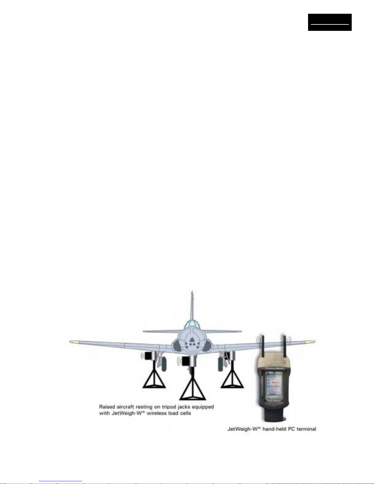
prior to actual aircraft weighment. Since the JetWeigh-
W system is completely wireless, no cable connection/
installation procedures are required. With an operating
range of 220 feet (70 meters), it should be easy to lo-
cate all load cells and the handheld terminal in functional
proximity to one another.
2.1.1 Load Cell Jack Point Configuration
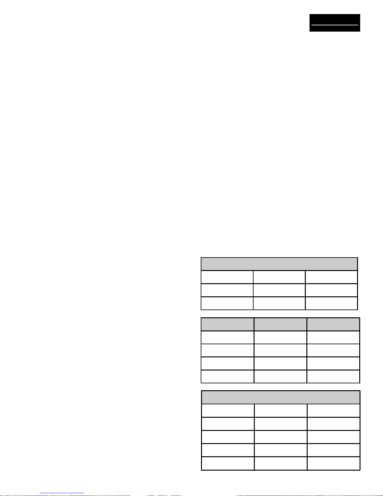
JetWeigh-W Systems accommodate jack point configu-
rations for 3-point, 4-point (helicopter or fixed wing) and
5-point aircraft. Recommended deployment of the load
cells is shown in Table 2-1. Make sure to match the load
cells and the mechanical adapters to ensure good re-
peatability of weighments.
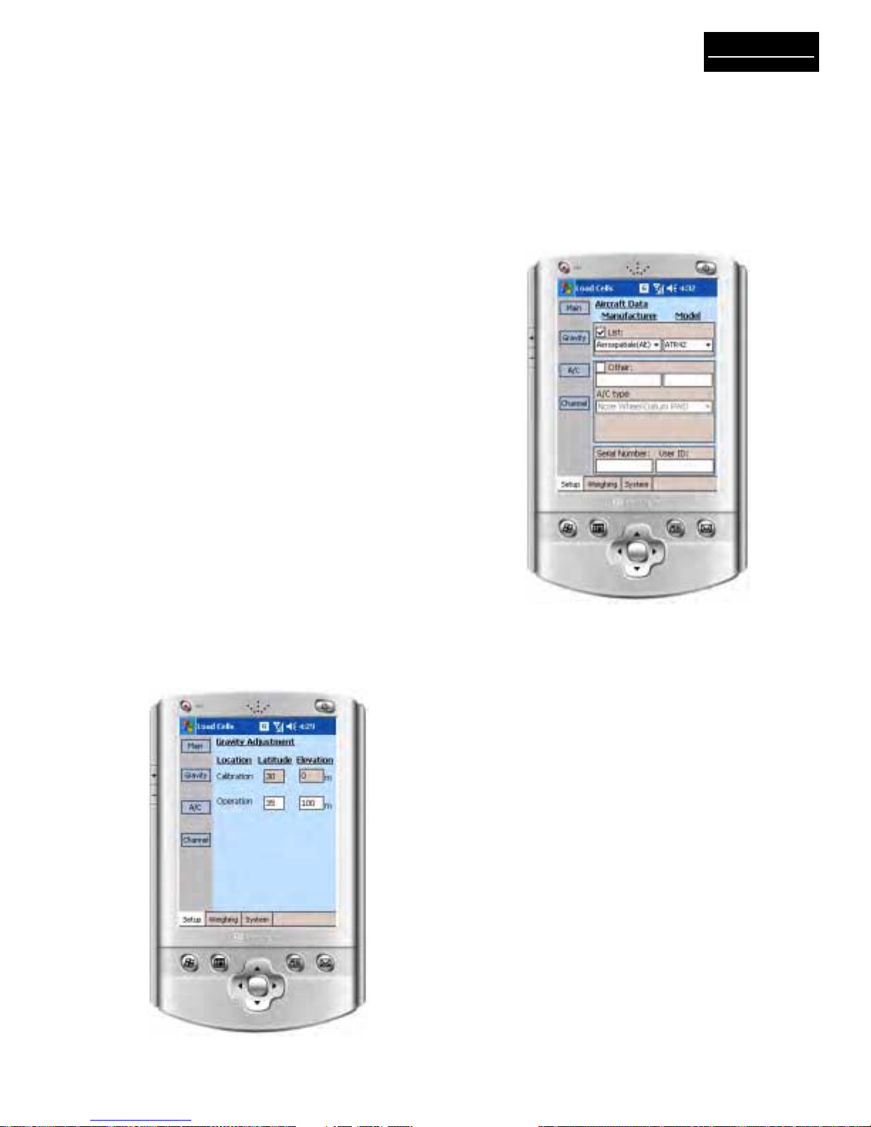
2.1.2 Preparation for Aircraft Weighing
1. Review the Equipment List of the aircraft being
weighed. Update the list as required. Make sure the
particular equipment, which will normally be installed,
but is missing at the time of the weighing, is added in
the later calculations.
2. Remove all equipment, which will not be included in
the above list.
3. Clean the aircraft to remove accumulated dirt, grease
and trapped water.
4. Fill the oil tanks to a known quantity. Fill all reser-
voirs, such as anti-icing fluid, to capacity.
5. Drain fuel tanks. If draining is not practical, fill the
tanks to capacity. Add or account for unusable fuel.
6. Determine the unit weight of fuel. Obtain a sample
from the fuel tank with the supplied fuel dipper (CG
kit) and pour the sample into the test tube. Using the
hydrometers (CG kit), the weight of fuel in pounds per
gallon can be observed. Variations in fuel weight, par-
ticularly in the case of jet aircraft, can cause
appreciable difference in the final empty weight and
CG determinations. Be alert for partially filled non-
symmetrical fuel tanks.
7. With tricycle gear aircraft, it is often desirable to
level the aircraft as closely as possible before lifting
on the jacks. Changing oleo strut extensions can do
this.
8. A stabilizing period of 20 minutes running concur-
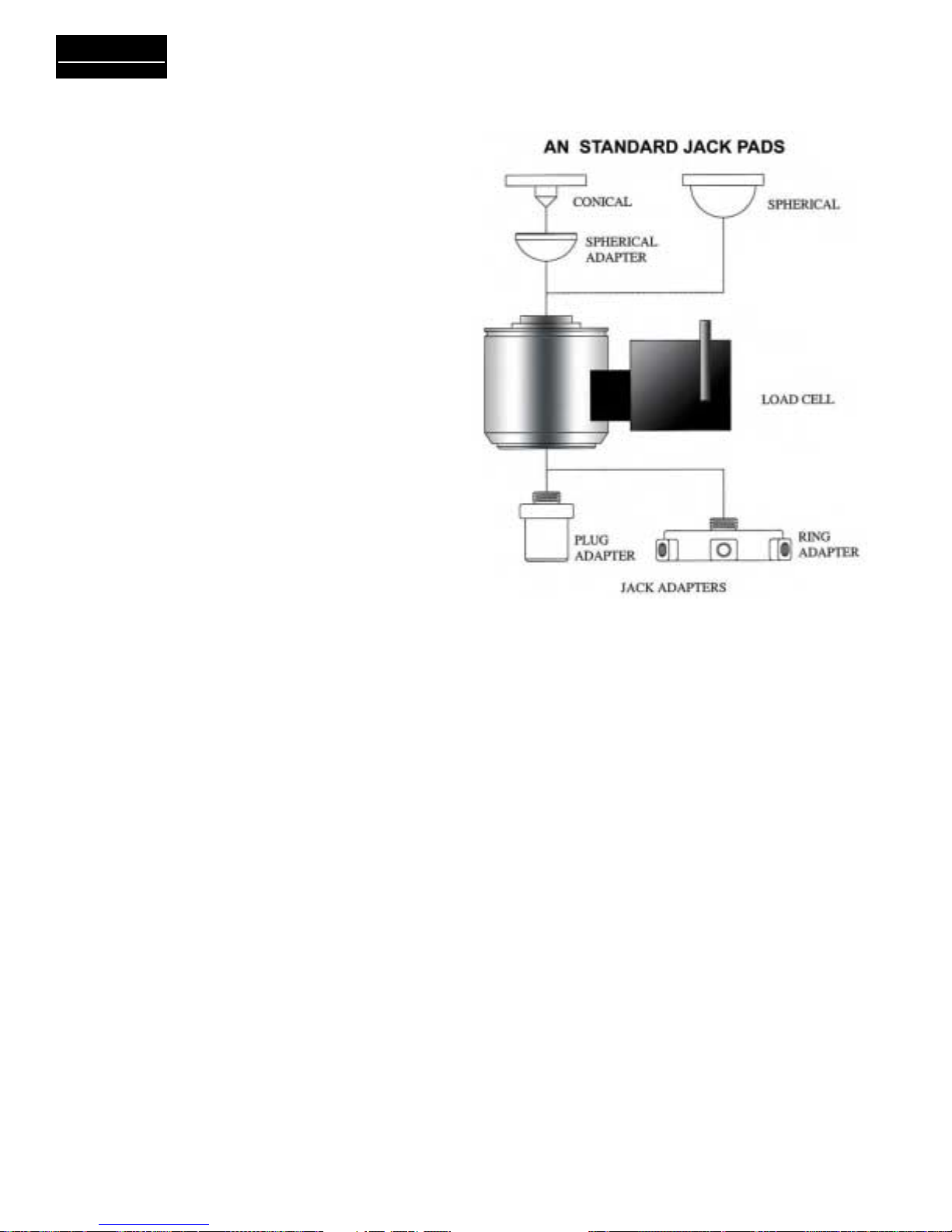
rently with warm-up period is advisable. When using
jack adapters, be sure the adapter is fully threaded into
the cell. With ring adapters, make sure it is centered
flush on the ram before tightening the set screws.
CAUTION
Use proper adapters to prevent jacks from
slipping or buckling. Damage to the aircraft or
inaccurate weight readings may result if improper
adapters are used. Never apply load to the rim of
the cell.
Color coded spherical adapters must be used in
conjunction with color coded load cells.
9. It is recommended that the load sensors be exer-
cised prior to performing an actual weighment.
Exercise the load sensors 2 – 3 times by lifting the
aircraft with the load sensors and jacking system in
place.
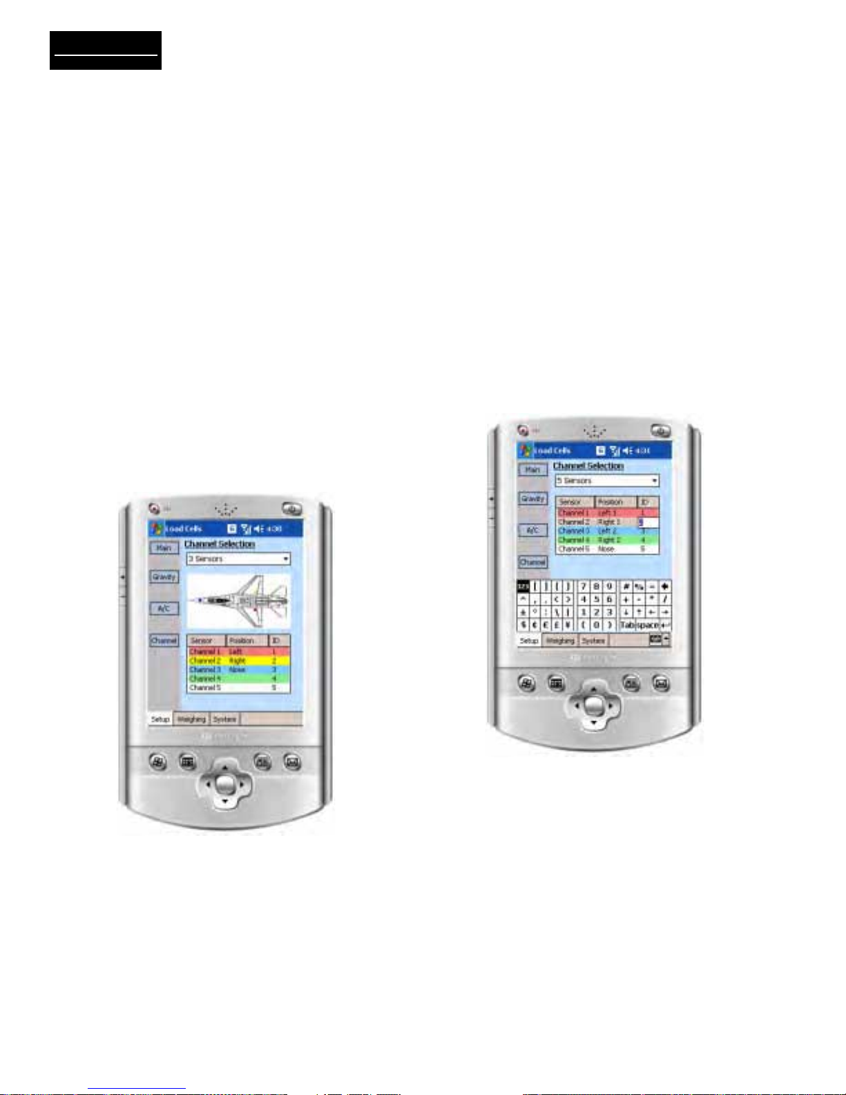
10. The JetWeigh-W is programmed to identify left,
right, nose, or the sum of both sensors on a bogie.
This requires that specific channels (load cells) be
dedicated to a specific location when preparing for
a weighment. These location identifiers will nor-
mally appear on the printout. However, they will not
appear during 1 and 2 channel operation. Table 2-1
shows the recommended layout for various configu-
rations.
3 Load Cells
Channel 1 Red Left
Channel 2 Yellow Right
Channel 3 Blue Nose
4 Load Cells Helicopter Fixed Wing
Channel 1 Red Fwd Left Left
Channel 2 Yel Fwd Right Right
Channel 3 Blue Aft Left Nose
Channel 4 Orng Aft Right Spare
5 Load Cells
Channel 1 Red Left (1)
Channel 2 Yellow Right (1)
Channel 3 Blue Left (2)
Channel 4 Green Right (2)
Channel 5 White Nose
Table 2-1. Jack Point Configuration