Vishay G4 Operating instructions

GB
G4 Multi Channel
Weighing Instrument
Program version 1.5.0.0
Operating instructions,
Quick installation
RM type


G4 Multi Channel Weighing Instrument
Contents
Introduction
General ............................................................. 1
Power supply ..................................................... 1
Start-up ............................................................. 2
Maintenance ..................................................... 2
Safety information ............................................. 2
Service panel
General ..............................................................3
Display ...............................................................3
Additional functions ............................................4
Operation
Zero indication and zero adjustment ..................5
Gross weight and net weight ..............................5
Taring .................................................................6
Editing Preset Tare ............................................7
Weight Printing ...................................................8
Level supervision ...............................................9
Accumulated Weights ......................................10
Flow display (program option) ..........................12
Scale Batching (program option) ......................13
Installation
Mechanical installation .....................................15
Electrical installation ........................................15
VIEWPAN module ............................................16
CPU unit ...........................................................17
WF IN, WF IN2 and HS WF2 ...........................18
Basic set-up
General ............................................................21
Hardware configuration ....................................21
Security lock .....................................................21
Common parameters .......................................22
Clock set-up .....................................................24
Scale calibration ...............................................25
Data sheet calibration ......................................28
Deadweight calibration .....................................31
Zeroing of gross weight ....................................36
Appendix 1
Common set-up values
Appendix 2
Scale set-up values

Operating instructions, Quick installation
PRECAUTIONS
READ this manual BEFORE operating or servicing this instrument.
FOLLOW these instructions carefully.
SAVE this manual for future reference.
WARNING
!Only permit qualified personnel to install and service this instrument.
Exercise care when making checks, tests and adjustments
that must be made with power on.
Failing to observe these precautions can result in bodily harm.
DO NOT allow untrained personnel to operate,
clean, inspect, maintain, service, or tamper with
this instrument.

G4 Multi Channel Weighing Instrument
Introduction
General
G4 is a high performance multi channel weighing instrument intended for industrial
systems. Its basic function is to convert the signals from strain gauge transducers
to useful weight information. Several types of communication interfaces are
supported by G4, which makes it easy to integrate the instrument into industrial
processes.
G4, type RM, is easily mounted on a DIN rail. All connections and the service
panel are accessible from the front end. By a LCD-display and four function keys
at the service panel, weight values are presented and parameter values can be
viewed and edited.
The basic configuration of the instrument performs weighing and flow rate
measurement. All functions are controlled by set-up parameters.
‘Operating instructions, Quick installation’ for G4 type RM includes basic installation
and set-up information, required for correct measuring with the instrument.
This description deals with the following points:
•Weighing with G4 type RM.
•Flow rate measurement (program option).
•Scale Batching (program option)
•Quick installation.
•Data sheet calibration.
•Deadweight calibration in two points.
Additional installation and set-up of more instrument functions, not covered by this
description, can also be performed, for example:
•Complete installation.
•Complete set-up.
•Setting of communication parameters.
•Table calibration.
•Level supervision.
•Program option activation.
For a complete instrument description, refer to:
G4 Multi Channel Weighing Instrument
Technical Manual
RM type
Power supply
Power supply to the weight indicator should not be turned off during weekends and
over-night. Continuous power supply to electronics and transducers prevents moisture
condensation in the units.
1

Operating instructions, Quick installation
Start-up
As soon as power is connected to the instrument, it will display 'Vishay' during a
start-up period, then the text ‘Start up, please wait’ is displayed after some seconds.
Then G4 automatically switches to normal measuring operation.
If the instrument is set for operator start-up, the text
‘Manual start. Push any key!’ will be shown until a key is pushed.
If a warm up time has been set, the text ‘Warming up Please wait!’
will be displayed before the instrument switches to measuring operation.
If any error is detected, the start-up stops and an error message will be displayed.
Maintenance
The G4 instrument needs no maintenance performed by the end-user. Any service
or repair work must be performed by qualified personnel. Contact your supplier.
Cleaning
Before cleaning the G4, break the power connection to the instrument.
Use a soft cloth to clean the exterior of the instrument.
Safety information
Utilization.
Before connecting power to the instrument, check that all fixation screws at the modules
are tightened so that the instruments functional grounding by the housing is maintained.
The instrument may only be utilized for the measurement and control functions, described
in the Technical Manual for G4 Multi Channel Weighing Instrument, RM type. It is
especially important to adhere to the load limits of the input/output connectors.
We accept no responsibility for any damage arising from improper operation.
Any changes to the instrument, which causes any function changes, may only be
carried out by the manufacturer, or after discussion with and permission by the
manufacturer.
Meaning of symbols, used in this manual
Direct current.
!Caution, risk of danger. Documentation needs to be consulted.
2

G4 Multi Channel Weighing Instrument
Service panel
General
The service panel VIEWPAN features a two-line, back lighted LCD-display and four
function keys. It can display the weight or flow value, or other selected information,
for one scale at a time.
It is also possible to connect a standard USB keyboard for PC to the USB connector
at the CPU module. The keyboard will work in parallel with the keys on VIEWPAN and
will make it easier to handle the configuration of the instrument, as it can be used as an
input for digits and characters.
The keyboard keys ' + ', ' – ', ' ↑' or 'Esc', and 'Enter' will correspond the VIEWPAN
keys ' + ', ' – ', ' ↑' , and ' ↵'.
Function key 'F11' on the keyboard can be used to access the 'Main Menu'.
Display
During measuring operation the function
keys + and – are used to toggle G4 RM
between display of measured values for
the scales in the instrument.
As G4 RM is in measuring operation
the top line shows a weight or flow value.
The bottom line, to the left, indicates
the actual scale number (S1:, S2: etc.),
and information about the measured value
(G=gross weight, N=net weight, M=motion,
Z=zero, Flow=flow display).
VIEWPAN module
3

Operating instructions, Quick installation
Additional functions
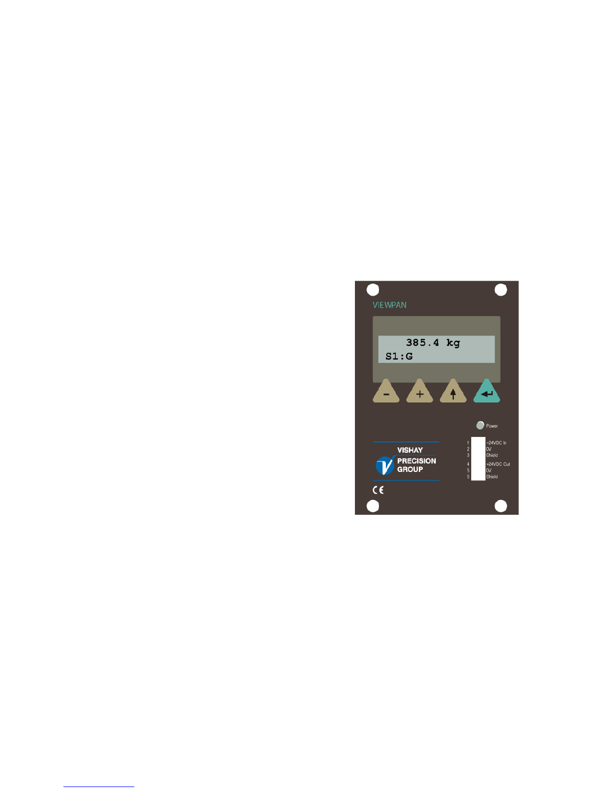
During measuring operation the additional functions for a scale that are activated
in the parameter set-up can be displayed to the right on the bottom line.
Key ↑toggles the display of additional functions 'on' and 'off'.
As the additional functions are displayed, the keys + and – will perform
scrolling of the additional functions that are available for the scale.
Possible functions are: Tare, B/N, Print, Zero, Levels, Pre.Tare, W/F.
See explanations of the functions below.
As key ↵is pressed, the displayed additional function will be performed
and display of additional functions will be toggled 'off'.
Explanations of the additional functions
Tare: This function performs taring, which means storing of the actual gross weight
as auto tare value and switching over to display of net weight.
Net weight being the gross weight minus tare.
B/N: This function performs toggling between display of gross weight, indicated by G,
and net weight, indicated by N.
Net weight cannot be displayed if the tare value in use is zero.
Print: This function initiates a print out of the displayed weight value.
Zero: This function performs Zero adjustment, a zeroing that can be performed only if
the gross weight is displayed, stable, and close to the basic zero. Basic zero setting of
the gross weight must be performed in the calibration sequences.
Levels: This function gives the possibility to rapidly view and edit the switch-over value
for the Levels, assigned to the scale.
Function Levels can be used only if at least one of the 32 Levels is assigned for
the scale in sub menu Param. Set-up / Level Superv.
Pre.Tare: This function opens menu Preset Tare for the scale, where the value of
preset tare can be viewed and edited.
Preset Tare can be opened only for scales that have Tare Corr.Mode set to
Preset or Auto+Preset in the scale calibration.
W/F: This function performs toggling between display of the weight value and
and the calculated flow value. Flow display can be selected only if program option
'Flow rate' is activated and Flow Calc. is set to On in the scale calibration.
4

G4 Multi Channel Weighing Instrument
Operation
Zero indication and zero adjustment
A basic zero setting of the gross weight for unloaded scale is performed at installation
as a part of the calibration. When a ‘good zero’ is displayed, the letter ‘Z’ is shown
under the measurement value.
Minor correction of the zero value may be needed and can rapidly be performed.
Zero adjustment
If, for unloaded scale, the letter ‘Z’ is not shown, but the gross weight is close to zero, a
rapid zero adjustment can be performed.
The gross weight must be stable (letter ‘M’ not shown)
and the zeroing function must be enabled.
Press key ↑.
Additional functions for the scale will appear
to the right on the bottom line.
Use key + or – to scroll to the Additional function
'Zero'.
Press key ↵to perform zero adjustment.
Gross weight, adjusted to zero, is displayed.
000.2 kg
S1:G Zero
000.0 kg
S1:G Z
000.2 kg
S1:G
Zero adjustment can only be performed if the accumulated deviation from the basic
zero setting in the last calibration is within -1 % to +3 % of the ‘Capacity’.
In other cases a new basic zero setting must be executed.
Gross weight and net weight
The gross weight is the total weight loaded on the scale after zero setting.
When gross weight is displayed the letter 'G' is shown under the measurement value.
The net weight is the difference between the gross weight and a tare value.
When net weight is displayed the letter 'N' is shown under the measurement value.
Net weight can not be displayed if the tare value is zero.
Switch-over between display of gross weight and net weight can be performed if
parameter 'Gross/Net key' is set to 'On'. This makes the additional function 'B/N'
available for the scale.
5

Operating instructions, Quick installation
When gross weight is displayed the letter 'G' is shown
under the measurement value.
Press key ↑.
Additional functions for the scale will appear
to the right on the bottom line.
Use key + or – to scroll to 'B/N'.
Press key ↵to change to display of net weight.
143.2 kg
S1:G
143.2 kg
S1:G B/N
Note: If the tare value is zero, net weight cannot be displayed.
When net weight is displayed, the letter 'N' is shown
under the measurement value.
Press key ↑.
Additional functions for the scale will appear
to the right on the bottom line.
Use key + or – to scroll to 'B/N'.
Press key ↵to change to display of gross weight.
Gross weight is displayed.
103.2 kg
S1:N
103.2 kg
S1:N B/N
143.2 kg
S1:G
Taring
Taring means storing of a tare value for the scale. Net weight will be calculated as
the difference between the gross weight and this tare value. If the tare value is zero,
net weight will not be displayed.
At default setting, taring can always be performed if parameter 'Tare key' is set to 'On'.
This makes the additional function 'Tare' available for the scale.
But the scale can also be set to allow taring only at stable weight (letter 'M' not shown).
In G4 two tare values can be stored, Auto tare and Preset tare.
Auto tare
By taring, the actual gross weight is stored as Auto tare value, and the scale will switch
to display of net weight 'zero'.
Press key ↑. Additional functions for the scale will
appear to the right on the bottom line.
Use key + or – to scroll to 'Tare'.
Press key ↵to perform taring.
In this example 14.5 kg is stored as an auto tare
value.
014.5 kg
S1:G Tare
000.0 kg
S1:N Z
6

G4 Multi Channel Weighing Instrument
Editing Preset tare
In this example Scale 1 is set for taring with ‘Preset tare’. The example shows editing
the value of ‘Preset tare’ from VIEWPAN.
Scale 1, set for preset taring,
is in normal weighing operation.
Press key ↑to see Additional functions.
Use key + or – to find the additional
function 'Pre.Tare'.
Press key ↵.
The value of Preset tare for the scale is shown.
Press key ↵to edit the value.
033.2 kg
S1:N
033.2 kg
S1:N Pre.Tare
Preset Tare 1
12.0 kg
If the Operator Lock is active, the Operator Code will be needed.
A cursor appears, meaning the value is ready
for editing. Use key + or – to edit one digit
at a time. Accept each digit by pressing key ↵.
Finish by pressing key ↵for 1 second.
The edited value of preset tare
for Scale 1 is displayed.
Press key ↑to return to normal weight operation.
Scale 1 displays the weight value.
035.2 kg
S1:N
Preset Tare 1
000010.0 kg
Preset Tare 1
10.0
7

Operating instructions, Quick installation
Weight Printing
A printer can be used to print the displayed weight or the displayed flow rate. The
printer must be connected to one of the G4 Instrument serial communication ports and
the communication parameters must be correctly set.
This example shows how to make a print out of the displayed weight for Scale 1 (the
displayed scale) from VIEWPAN.
Scale 1 is selected and in normal weighing operation.
Press key ↑to see Additional functions.
Use key + or – to find the additional function 'Print'.
Press key ↵.
The displayed weight value is printed, indicated
by a 'P' in the display.
033.2 kg
S1:N
033.2 kg
S1:N Print
033.2 kg
S1:N P
The print indicator ‘P’ is shown where the ‘Z’ (zero) or ‘M’ (motion) indications normally
appear. The print indication will appear even if no printer is configured and indicates
that the weight is accumulated.
Print out will be performed provided that:
• The displayed weight is higher than the value of 'Min. Weight Print'. No print out
will be done if the weight is too low.
• If 'Motion Check' is turned on, the displayed weigh must be stable ('M' not
shown).
If the weight is not stable ('M' shown), printing will be delayed and the 'P' will be
flashing. When the weight has become stable ('M' not shown) printing will be
performed.
8

G4 Multi Channel Weighing Instrument
Level supervision
With G4 it is possible to supervise different weighing signals at defined levels.
The instrument contains 32 supervising units, Level 1 to Level 32, which can be
connected to the scales by the parameter set-up.
All Levels, connected to a scale, can easily be shown by scrolling at the display.
Edit levels
The defined supervising levels for a scale are easily viewed and edited
from VIEWPAN at G4 RM.
Editing of levels is performed without interrupting the normal weighing operation.
Example: Scale 1, with some connected Levels,
is in normal weighing operation.
Press key ↑to see Additional functions.
Use key + or – to find the additional
function 'Levels'.
Press key ↵.
The value of the first Level for Scale 1 is shown.
Use key + or – to scroll all Levels for the scale.
Press key ↵to edit a displayed value.
If the Operator Lock is active, the Operator Code
will be needed.
123.4 kg
S1:G
123.4 kg
S1:G Levels
Level 2
50.0 kg
A cursor appears, meaning the value is
ready for editing. Level 2
Use key + or – to edit one cursor position at a time. +000055.0
Accept the value of each position by pressing key ↵.
Finish by pressing key ↵for 1 second.
The new value for the edited Level is displayed. Level 2
Press key ↑to return to normal weight operation. 55.0 kg
9

Operating instructions, Quick installation
Accumulated Weights
Every time a weight is printed the weight value is added to an accumulated value for
each scale. Accumulation is done even if no printer is set-up or connected.
Accumulated weights can be changed and set to zero from menu 'Accum. Weights'.
This menu is reached from the 'Main Menu'.
Zero setting of accumulated weights for all scales
The example below shows how to set the accumulated weights for all scales in the
instrument to zero.
Press the keys + and ↑simultaneously
for 1 second to open 'Main Menu'.
The 'Main Menu' is displayed.
Use key + or – to find sub menu 'Accum. Weights'.
Press key ↵.
Menu 'Accum. Weights' is displayed with the
accumulated weight for the first scale on the lower
row.
Press the key + a number of times until
'Zero ALL values?' is shown.
Press key ↵(Yes) to set the accumulated weights
for all scales to zero.
123.4 kg
S1:G
Main Menu
Accum. Weights
A
ccum.Weight,S1
3798.100 kg
Zero ALL values?
No Yes
If the Operator Lock is active, the Operator Code
will be needed.
A confirm question will be shown.
Press key ↵(Yes) again to perform the zero setting.
The instrument returns to accumulated weights display.
Press key ↑several times to return to
weight display.
Continue?
No Yes
A
ccum.Weight,S1
0.000 kg
10

G4 Multi Channel Weighing Instrument
Edit (zeroing) of accumulated weight for one scale
The example below shows how to edit (zeroing) an accumulated weight for a scale.
Press the keys + and ↑simultaneously
for 1 second to open 'Main Menu'.
The 'Main Menu' is displayed.
Use key + or – to find sub menu 'Accum. Weights'.
Press key ↵.
Menu 'Accum. Weights' is displayed with the
accumulated weight for the first scale on the lower
row.
The keys + and – can be used to scroll the list
of available scales.
Press key ↵to edit a displayed value.
If the Operator Lock is active, the Operator Code
will be needed.
A cursor appears, meaning the value is
ready for editing.
Use key + or – to edit one cursor position at a time.
Accept the value of each position by pressing key ↵.
Finish by pressing key ↵for 1 second.
The new value is displayed.
Press key ↑several times to return to
weight display.
123.4 kg
S1:G
Main Menu
Accum. Weights
A
ccum.Weight,S1
3798.100 kg
A
ccum.Weight,S1
+0000000000.000
A
ccum.Weight,S1
0.000 kg
11

Operating instructions, Quick installation
Flow display (program option)
When option Flow display is activated for a scale, the additional function 'W/F' can be
shown in the scale display.
When 'W/F' is made visible during weight display, and key ↵is pressed,
this will switch the scale over to display of flow value.
When 'W/F' is made visible during flow display, and key ↵is pressed,
this will switch the scale over to weight display.
Example: Scale 1, with the Flow display activated,
is in normal operation, displaying
an increasing gross weight.
Press key ↑to see Additional functions.
Use key + or – to find the additional
function 'W/F'.
Press key ↵.
The measurement value for Scale 1
changes from weight to flow.
As the scale is displaying the flow value,
press key ↑to see Additional functions.
Use key + or – to find the additional
function 'W/F' .
Press key ↵.
The measurement value for Scale 1
changes from flow to weight.
064.4 kg
S1:G M
096.8 kg
S1:G M W/F
2.15 kg/s
S1:Flow
2.15 kg/s
S1:Flow
131.1 kg
S1:G M
2.15 kg/s
S1:Flow W/F
12

G4 Multi Channel Weighing Instrument
Scale Batching (program option)
The RM instrument is a complete multi scale batcher but it is not intended as an
operator interface for batching. It is possible to set-up the batching sequences
from the RM instrument front panel. However for control (start, stop, reset etc) of
the batching sequence should a supervising computer be used (PLC, SCADA
system etc).
An animated symbol is shown in the weight display, when batching is active
(running) for the selected scale.
Animated batching indicator symbol
Batched weights
For each scale accumulated weights (batched material) will be created.
In the menu ‘Batched Weights’, in the ‘Main Menu’, are the accumulated weights for
each configured scale to be found. Each batched weight can be changed, e.g. set to
zero (see ’Accumulated Weights’ above).
13

Operating instructions, Quick installation
14

G4 Multi Channel Weighing Instrument
Installation
Mechanical installation
G4 Multi Channel Weighing Instrument type RM is designed for mounting on a flat
surface by DIN rail, for example in a protective cabinet. To remove the instrument
from the rail, the black lever at the lower bottom side of the instrument must be
engaged.
All electrical connections to the instrument are made at the front side so enough
room for connectors and appropriate cable ducts should be arranged.
Electrical installation
The field wiring of the instrument shall be suitable to the environment
(e.g. chemically) in the end-user application. !
Field wiring installation shall comply with any national regulations, hereunder
National Electrical Code (NEC) for US and/or Canadian Electrical Code for Canada.
• A switch or circuit-breaker shall be included in the building installation.
• The switch shall be in close proximity to the equipment and
within easy reach of the operator
• The switch shall be marked as the disconnecting device for the equipment.
• The equipment switch or circuit-breaker employed as disconnecting device shall
comply with relevant requirements of IEC 60947-1 and IEC 60947-3.
The power supply for the instrument should be made via an external DC source.
All electrical connections to the instrument, including connection to ground,
are made via plug-in terminal blocks. Shielded cables are needed, except for
the power input, and the cables should be routed so that electromagnetic
interference from power cables is avoided.
WARNING
Make sure that that the power to the instrument is turned off before:
- any modules are removed from or inserted in the instrument.
- any connections are connected to or disconnected from the instrument.
All modules should be regarded as ESD sensitive. Make sure that an ESD safe
environment is maintained when inserting modules, removing modules and
when handling modules separately from the instrument. Modules must be kept
in metallised ESD bags when not mounted in the instrument.
15

Operating instructions, Quick installation
VIEWPAN module
!
The output of the external dc supply must be rated 24 V , ±15%
including fluctuations, min. 40 W. The supply must provide Double Insulation
between Mains parts and 24 V SELV or SELV-E circuit; and a limited-energy
circuit (max. available current 8 A). For the US market this energy limit
can be achieved with an ANSI/UL 248-14 fuse rated 5 A.
For other markets an IEC 60127 T type fuse rated 4 A may also be used.
The power supply unit, designed to supply the complete instrument, is incorporated
in the VIEWPAN module.
24 V In
Terminals 1, 2, and 3.
Connect power to terminal 1 (positive) and
terminal 2 (0 V). To achieve functional
grounding, terminal 3 should be connected
to ground.
24 V Out
Terminals 4 (positive) and 5 can be used
to supply max. 100 mA to logics, like
outputs and inputs.
+24 V In
0 V
Ground
+24 V Out
0 V
1
VIEWPAN
2 0 V
3 Shield
4
5 0 V
6 Shield
+24 VDC In
+24 VDC Out
16
Other manuals for G4
5
Table of contents
Other Vishay Accessories manuals

Vishay
Vishay TSSP770 Series User manual

Vishay
Vishay VT 200 User manual

Vishay
Vishay TSSP960 Series User manual

Vishay
Vishay VT300 User manual

Vishay
Vishay VT400 User manual

Vishay
Vishay TSSP770 Series User manual

Vishay
Vishay G4 User manual

Vishay
Vishay TSSP60 Series User manual

Vishay
Vishay JetWeigh-W User manual

Vishay
Vishay TSSP60 Series User manual
Popular Accessories manuals by other brands

Intenso
Intenso S10000-C user manual

lynx System Developers
lynx System Developers RadioLynx quick start guide

Tefcold
Tefcold UR90G-Sub-Zero Original instructions

Johnson Controls
Johnson Controls 7351J Installation and maintenance instructions

Osram
Osram DALI LS/PD CI instruction manual

ipf electronic
ipf electronic UT300025 manual