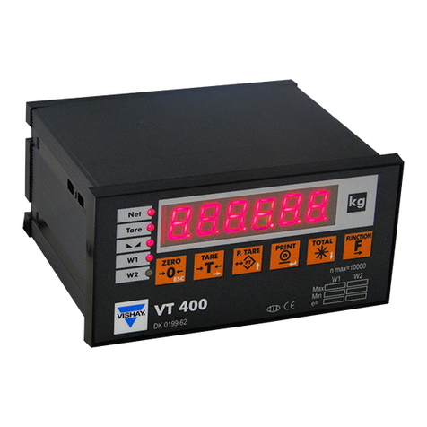
Vishay VT300 User manual

VT300
Weighbridge Indicator
Technical Manual
Revision A4, September 2006 Doc # TM-VT300-EN

Table of Contents
VT300 Technical Manual, Rev. A4 ii Doc # TM-VT300-EN
Table of Contents
TABLE OF CONTENTS ................................................................................ II
TABLE OF FIGURES .................................................................................VII
LEGAL NOTICE ...................................................................................... VIII
WARRANTY.............................................................................................. IX
SAFETY INSTRUCTIONS .............................................................................X
DECLARATION OF CONFORMITY .............................................................XII
ABOUT THIS DOCUMENT ....................................................................... XIII
1TECHNICAL SPECIFICATIONS......................................................... 15
1.1 GENERAL ........................................................................................... 15
1.2 ANALOG INPUT .................................................................................... 16
1.3 ANALOG OUTPUT (OPTIONAL) ................................................................... 16
1.4 DIGITAL INPUT .................................................................................... 17
1.5 DIGITAL OUTPUTS ................................................................................ 17
2INSTALLATION .............................................................................. 18
2.1 SITE REQUIREMENTS ............................................................................. 18
2.2 MOUNTING THE INDICATOR ...................................................................... 18
2.2.1 Desktop Model (Aluminum Enclosure).................................................. 18
2.2.2 Wall-Mount Model (Stainless Steel Enclosure) ....................................... 19
2.3 CONNECTING LOAD CELLS ....................................................................... 20
2.3.1 Desktop Model (Aluminum Enclosure).................................................. 20
2.3.2 Wall-Mount Model (Stainless Steel) ..................................................... 21
2.3.3 Load Cell Operating Parameters.......................................................... 21
2.4 SERIAL CONNECTIONS............................................................................ 22
2.4.1 Printer and PC Cables........................................................................ 22
2.4.2 RS485 Cable Connections .................................................................. 22
2.5 CONNECTING POWER ............................................................................. 23

Table of Contents
VT300 Technical Manual, Rev. A4 iii Doc # TM-VT300-EN
3DISPLAY, KEYS AND MENUS........................................................... 24
3.1 THE DISPLAY ...................................................................................... 24
3.1.1 Status Annunciators.......................................................................... 25
3.1.2 Common Messages Shown on the Display ............................................ 25
3.2 FRONT PANEL KEYS ............................................................................... 26
3.2.1 Using Keys to Perform Operations ....................................................... 26
3.2.2 Using Keys to Enter Information ......................................................... 27
3.3 THE MENU ......................................................................................... 27
3.3.1 Using the Menu ................................................................................ 27
3.3.2 Menu Structure and Options Summary................................................. 28
Main Menu.................................................................................................................... 28
Main > WEIGH .............................................................................................................. 28
Main > VFILE ................................................................................................................ 29
Main > TFILE ................................................................................................................ 29
Main > MISC................................................................................................................. 30
Main > SYSTEM............................................................................................................. 30
Main > SYSTEM (cont.) .................................................................................................. 31
4CALIBRATION ................................................................................ 32
4.1 SELECTING CALIBRATION METHOD ............................................................. 32
4.2 CALIBRATION WITH STANDARD WEIGHTS...................................................... 33
4.2.1 Zero (Dead-Load) Calibration ............................................................. 33
4.2.2 Span Calibration............................................................................... 33
4.3 ELECTRONIC CALIBRATION (E-CAL) ........................................................... 34
4.3.1 Calculating Calibration Values............................................................. 34
4.3.2 Setting Zero Calibration (Dead-Load) Value.......................................... 35
4.3.3 Span (Max. Capacity) Calibration ........................................................ 35
4.4 STORING CALIBRATION DATA ................................................................... 35
4.5 LOCKING AND UNLOCKING CALIBRATION....................................................... 36
4.5.1 Sealing Indicator Enclosure with Stickers.............................................. 36
4.5.2 Securing Load Receptor..................................................................... 37
4.5.3 Checking Seal Status and Audit Trail Counter........................................ 37
5GENERAL SYSTEM PARAMETERS..................................................... 38

Table of Contents
VT300 Technical Manual, Rev. A4 iv Doc # TM-VT300-EN
5.1 EDITING PARAMETERS ............................................................................ 38
5.2 SYSTEM >1/2CAL >PAR MENU ............................................................ 39
5.2.1 Dual-scale Connecting And Parameter Settings ..................................... 41
5.3 SYSTEM >SET >OPER ...................................................................... 41
6SERIAL COMMUNICATION .............................................................. 43
6.1 SERIAL PORTS CONFIGURATION................................................................. 43
6.1.1 RS232 Serial Port ............................................................................. 43
6.1.2 RS485 Serial Port ............................................................................. 43
6.2 SETTING PORT OUTPUT .......................................................................... 44
6.2.1 Setting Port 1 Output ........................................................................ 44
6.2.2 Setting Port 2 Output ........................................................................ 45
6.3 OUTPUT FORMATS................................................................................. 46
6.3.1 Continuous Weight Output ................................................................. 46
6.3.2 Continuous Weight Output with Dual Scale Operation............................. 47
6.3.3 Continuous Weight With Tare ............................................................. 47
6.3.4 Alibi Transmit................................................................................... 49
6.3.5 Alibi Mode Commands ....................................................................... 49
Transmit Displayed Weight ............................................................................................. 49
Command “ZERO” ......................................................................................................... 49
Character for Print-on-Demand ....................................................................................... 50
6.3.6 EDP Protocol Output.......................................................................... 50
6.3.7 Remote Printer Output....................................................................... 51
6.3.8 Master-Slave Protocol........................................................................ 51
Master-Slave Commands................................................................................................ 53
Gross-Tare-Net Weight Transmission ............................................................................... 56
6.4 DEFAULT TICKET FORMATS ...................................................................... 57
6.5 CUSTOM TICKET FORMATS ....................................................................... 58
6.5.1 Creating a Custom Ticket Format ........................................................ 58
6.5.2 Downloading and Uploading Custom Ticket Formats............................... 60
7OUTPUTS AND DIGITAL INPUT....................................................... 62
7.1 SPECIFICATIONS .................................................................................. 62
7.1.1 Digital Outputs................................................................................. 62

Table of Contents
VT300 Technical Manual, Rev. A4 vDoc # TM-VT300-EN
7.1.2 Analog Outputs ................................................................................ 62
7.1.3 Digital Input (Tilt Switch)................................................................... 62
7.2 CONNECTING DIGITAL OUTPUTS AND TILT SWITCH .......................................... 63
7.3 SETTING THRESHOLDS FOR DIGITAL SETPOINTS.............................................. 63
7.3.1 Setpoint Options............................................................................... 64
Setpoint On/Off Combinations.........................................................................................64
7.4 CONFIGURING ANALOG OUTPUT................................................................. 65
7.4.1 Connecting PCB and Setting Jumper.................................................... 65
7.4.2 Setting Analog Output Parameters ...................................................... 66
7.4.3 Calibrating D/A Converter .................................................................. 67
7.5 USING THE TILT SWITCH......................................................................... 68
7.5.1 Tilt Switch Options............................................................................ 68
8SERVICE OPERATIONS AND TESTING ............................................. 69
8.1 SERVICE OPERATIONS ............................................................................ 69
8.1.1 Setting and Changing System and Operator Password (SYSTEM > PIN) .... 69
8.1.2 Setting Date, Time and Serial Number (SYSTEM > DATE)....................... 70
8.1.3 Resetting Parameters (INIT)............................................................... 70
8.1.4 Displaying Remaining Battery Capacity (WEIGH > BATTERY)................... 71
8.1.5 Checking Calibration Seal (MISC > 1/2OIML)........................................ 71
8.1.6 Viewing Load Cell mV (TEST > CVM) ................................................... 71
8.1.7 Viewing A/D Count (TEST > A/D)........................................................ 71
8.1.8 Locking and Unlocking Keys ............................................................... 72
8.2 TESTING THE INDICATOR......................................................................... 72
8.2.1 Testing ROM/RAM Integrity (TEST > MEM) ........................................... 72
8.2.2 Testing the Keypad and Display (TEST > KBD, LCD) .............................. 73
8.2.3 Testing Digital Input and Outputs (TEST > I/O)..................................... 73
8.2.4 Testing Data Received on Both Serial Ports (TEST > PORT)..................... 74
9SPECIAL WEIGHBRIDGE OPERATIONS ........................................... 75
9.1 CUSTOMIZING WEIGHBRIDGE DESCRIPTIONS ................................................. 75
9.2 BATCH WEIGHING ................................................................................ 76
10 TROUBLESHOOTING....................................................................... 78
Other manuals for VT300
1
Table of contents
Other Vishay Accessories manuals

Vishay
Vishay TSSP60 Series User manual

Vishay
Vishay TSSP960 Series User manual

Vishay
Vishay TSSP96038TR User manual

Vishay
Vishay G4 Operating instructions

Vishay
Vishay VT400 User manual

Vishay
Vishay JetWeigh-W User manual

Vishay
Vishay G4 User manual

Vishay
Vishay G4 User manual

Vishay
Vishay PM 1155 User manual

Vishay
Vishay VCNL3020 User manual