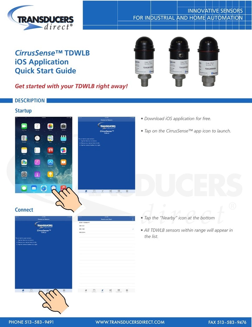
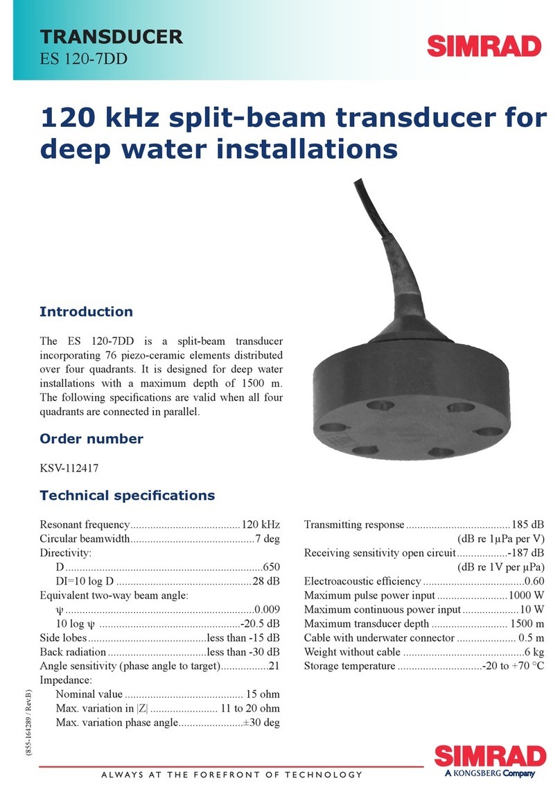
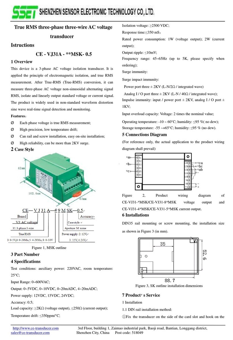
Visi-Trak A49-1120P User manual


General
The Visi-Trak®Bi-directional Transducers utilize a patented sensing process in conjunction
with a specially modified rod to provide non-contact position and velocity detection of linear
motion
devices. The transducer is typically used with a cylinder rod (or external tail rod) which has
been pre-grooved and plated through the Visi-Trak®modification process. This combination
generates two digital square wave pulse trains, 90Oout of phase, each having an approxi-
mate duty cycle of 50%, as the rod is moved. These digital outputs are typically interfaced to
electronic assemblies used to monitor or control position, velocity or direction. Two trans-
ducer models are presently available and provide position resolutions of 0.0125" (20 Pitch)
and 0.025" (10 Pitch) respectively.
Caution!
The Visi-Trak®Transducer must be handled with care at all times. The transducer incorpo-
rates a thin metallic face and permanent damage can result if this face is scratched, dented,
or abused. Also, care must be taken when wiring the transducer since improper wiring or
short circuits may destroy the device. In all cases; improper wiring, short circuits, or physical
damage to the transducer does not constitute a warranty failure. If sensor failure does occur
under normal operating conditions and within the warranty period, the defective device must
be returned to the factory for inspection prior to warranty replacement or credit.
Before returning a transducer, contact Visi-Trak Worldwide, LLC.
for a Return Authorization Number (RA).
Visi-Trak® is a registered US trademark of Visi-Trak Worldwide, LLC.
Visi-Trak Worldwide, LLC
8400 Sweet Valley Drive
Suite 406
Valley View, Ohio 44125-4244
216. 524-2363
Fax 216. 524-9594
www.visi-trakworldwide.com
VISI-TRAK®
BI-DIRECTIONAL TRANSDUCER
INSTALLATION AND TESTING PROCEDURE
Visi-Trak ®Transducer Part Number Information
0.0125" Resolution Transducer (20 Pitch) A49-1120P
0.0250" Resolution Transducer (10 Pitch) A49-1110P
0.250mm Resolution Transducer (1mm Pitch) A49-111mm
0.500mm Resolution Transducer (2mm Pitch) A49-112mm
MS Receptacle (4 Pin Male) X43-06937
MS Mating Plug (4 Pin Female) X43-06940
MS Cable Clamp X43-06928

Installation
The transducer has already been pre-tested at the factory and a small sticker should
be located on the face. This sticker provides the recommended gapping distance
(0.005") between the rod and the transducer. If the sticker does not exist, proceed to
install two layers of Scotch tape on the face (0.0025" nominal thickness) and make
sure the tape covers the face only. Any tape located on the sides of the transducer
body may prevent proper insertion of the transducer into the transducer mounting block
due to the close tolerances that exist.
Carefully slide the transducer into the proper hole of the transducer mounting block un-
til it touches the rod. The internal magnet will help to pull the transducer to the rod. Do
not let the transducer “bang” into the rod, but carefully control the speed of the trans-
ducer contacting the rod by holding the leads so the transducer slowly descends into
the hole.
Once in contact with the rod, rotate the
transducer body until the flat portion is
perpendicular to the direction of rod motion and
facing the set screw holes, as shown in either
Figure 1. or Figure 2., below. In typical cylinder
applications, the flat edge should face the rod
end of the cylinder. If the transducer mounting
block is mounted such that the flat edge is not
facing the rod end of the cylinder, the lead and
trail wires of the transducer will have to be
reversed (pins A and D of the MS connector).
The transducer has two internal
“sensing heads” which generate independent
output signals, so it is important that the flat
edge is properly positioned. When the flat edge
is correctly positioned, and the appropriate gap
between the transducer and the rod has been
established, tighten the two set screws that hold
the transducer in place one quarter turn beyond
finger tight.
Do not over tighten or damage may result.
Continue to next page….
Visi-Trak® is a registered US trademark of Visi-Trak Worldwide, LLC.

Sometimes better results are obtained when the transducer is allowed to “float” on the
grooved rod. This will reduce wear on the transducer, and ensure that the transducer
remains in contact with the rod. To “float” a transducer, simply loosen the set screws
slightly. The magnet in the end of the transducer will keep it in contact with the rod.
If the transducer was supplied without the connector attached, or the transducer can't
be installed with the connector attached, proceed to the next section.
For transducer assemblies which have the connector soldered on, simply push the ex-
tra wire length into the mounting hole until the connector rests flush on the mounting
surface. Take caution with these wires so that they do not bind or break.
Use four #4-40 screws to attach the connector to the mounting block. The assembly is
now ready for use.
Wiring
If the transducer was supplied without a connector, or the transducer can't be installed
with the connector attached, cut the wire leads to allow for about 2" of slack from the
connector mounting surface. Strip each lead 1/4" and proceed to solder the leads to
the connector, according to Figure 3. If the transducer mounting block is mounted
such that the flat edge is not facing the rod end of the cylinder, the lead and trail wires
of the transducer will have to be reversed (pins A and D of the MS connector). When
soldering, make sure that a clean solder joint results, and no solder bridges exist.
Once completed, carefully push the extra wire length into the mounting hole until the
connector rests flush on its mounting surface. Take caution so that the wires do not
bind or break. Install the required #4-40 screws for attaching the connector.
The assembly is now ready for use.

Testing
Prior to applying power to the transducer assembly, make sure that all power and sig-
nal connections are properly made to the external electronics and use good quality
shielded cable to help reduce noise interference on the output signal lines.
Although transducer testing is best accomplished with the use of an oscilloscope, a
standard voltmeter may also be used. The most convenient place to test a trans-
ducer’s signals is at the external electronics' terminals rather than at the transducer's
connector as shown in the following table.
Part Number Description Lead Input Trail Input DC Ground
MVO-03289 Analog Position Indicator BoardTB1-4 TB1-3 TB1-5
MVO-06587 Analog Position/Velocity Board TB1-3 TB1-4 TB1-2
MVO-03272 2300 Input Signal Conditioner TB1-4 TB1-3 TB1-2
MVO-03179 2300 Input Signal Conditioner TB1-4 TB1-3 TB1-2
with Analog Outputs
MVO-05964 2300 Input Signal Conditioner TB1-4 TB1-3 TB1-2
with Analog Outputs, Metric
MVO-06407 2300 Input Signal Conditioner / TB1-4 TB1-3 TB1-2
Counter
MVO-06408 Sensor/Buffer Board TB1-3 TB1-4 TB1-2
MVO-06235 Differential Signal Driver TB1-3 TB1-4 TB1-2
MVO-06458 Single Ended Signal Driver TB1-3 TB1-4 TB1-2
MVO-06214 External Interface TB1-6 TB1-4 TB1-7
MVO-05282 Multiplexer Board
Machine #1 TB1-20 TB1-19 TB1-55
Machine #2 TB1-18 TB1-17 TB1-56
Machine #3 TB1-16 TB1-15 TB1-57
Machine #4 TB1-14 TB1-13 TB1-58
Machine #5 TB5-35 TB5-36 TB5-101
Machine #6 TB5-37 TB5-38 TB5-102
Machine #7 TB5-39 TB5-40 TB5-103
Machine #8 TB5-41 TB5-42 TB5-104
Visi-Trak® is a registered US trademark of Visi-Trak Worldwide, LLC.

Using a Voltmeter:
To test the transducer's lead and trail signals using a voltmeter, first apply power to the
transducer assembly, then hold the positive probe of the voltmeter on either the lead
input terminal, or the trail input terminal, and the negative probe on the DC ground ter-
minal of the external electronics. Next, initiate rod motion. As the rod is moved, the
voltmeter reading should stabilize at approximately 5-7 volts DC, which is the average
of the digital square wave signal. With no rod motion, the meter will typically read ei-
ther zero or 12 volts DC, depending on the location of the sensing head to the groove
profile. It might be easier to read the voltmeter if the rod is moved forward slowly, or
when the rod retracts. Be sure to check both lead and trail signals to confirm proper
readings.
If the voltmeter doesn't stabilize, remove the transducer from the mounting block and
manually move it along the modified rod, being careful to temporarily remove the posi-
tion transducer's cable so as not to short the terminals of the MS connector on any
metal objects. If this procedure is used, be sure to maintain continuous contact of the
transducer face to the center of the rod, and to keep the flat side perpendicular to the
direction of rod motion. If this method results in satisfactory operation of the trans-
ducer, check the mounting structure arrangement in relation to the sensor to ensure
that the transducer is being properly installed and mounted.
Although a voltmeter will not show problems typically caused by improper mounting
(poor duty cycle and quadrature), it will allow you to see the continuous high or low lev-
els, at the lead or trail signal input terminals, displayed by most defective Transducers.
The presence of continuous high or low voltages at the external electronics' input ter-
minals doesn't rule out improper mounting, or defective cabling as possible problems.
Visi-Trak® is a registered US trademark of Visi-Trak Worldwide, LLC.

Using an Oscilloscope:
It is best to inspect the transducer outputs using a two channel oscilloscope so that
both digital outputs can be viewed simultaneously. Set the scaling on 5 volts per divi-
sion vertical and approximately 2 milliseconds per division horizontal. The horizontal
scale may need adjustment based on the speed of rod motion. Connect the channel 1
probe to the lead input terminal, the channel 2 probe to the trail input terminal, and the
ground lead to the DC ground terminal of the external electronics. Use caution when
connecting or disconnecting the scope probes to ensure that any two terminals are not
accidentally shorted together. This may result in permanent damage to the transducer.
Apply power to the transducer assembly and initiate rod motion (it is recommended to
maintain slow rod speed when monitoring the outputs so that the scope traces may be
easily analyzed). During rod motion, view the scope traces and confirm that they ap-
pear as shown in Figure 4, below. Adjustments of the horizontal sweep and/or trigger
level on the scope may be necessary to obtain a better trace.
The pulses should illustrate a duty cycle of approximately 50%. That is, the duration of
the high level should be approximately the same as the duration of the low level. This
should be true for both pulse traces. Also confirm that a "phase shift" is evident be-
tween the two channels. This shift should be approximately 90 degrees, or in other
words, one pulse should rise or fall in the middle of the other pulse's high or low state.
Although these items do not need to be absolutely perfect, they should be reasonably
close to obtain proper functioning of the electronics. Typically, if a transducer becomes
defective, one output will look as shown and the second will show either a continuous
high or low voltage, or show a very poor duty cycle. Slight rotation of the transducer in
the block occasionally improves the duty cycle and quadrature (phase shift), however,
continuous high or low outputs indicate a defective device.

Special note for True-Trak 2020™ Monitoring and Sure-Trak™ Control System Users:
A “Transducer Test” program is built in the True-Trak 2020™ system. You can invoke the
program from main menu “Monitor” select “FasTrak Board Monitor” to start FasTrak
Board Monitor program. From FasTrak Board Monitor program select “View” then select
submenu “FasTrak Board Interface” to run FasTrak Interface program. “Transducer Test”
program is one of the function selections inside the FasTrak Interface program. For Sure-
Trak Control System user you can press F6 function key to enter the transducer test
mode From SCI (Shot Control Interface) program. The transducer test program provides
an oscilloscope-like display as shown below. Pressing F1 from within the transducer test
screen will take a sample of the transducer pulses.
The best time to sample the pulses is during shot retract. While the cylinder is retracting,
press the F1 function key. The pulses will be displayed as shown below. The figure be-
low shows an ideal condition. Note that the duty cycles of the pulses is exactly 50%.
That is, each pulse is high the same amount of time it is low. Also note the 90 degree
phase shift between the two pulses. The trace in the figure shows a perfect 90 degree
quadrature. In reality, traces taken from an actual machine may not be quite this good.
However, they should be close. Some variation in duty cycle and quadrature is normal.
A poor condition is one in which one or both of the pulses have a poor duty cycle. A
"skinny" pulse, or one that is high or low for only a short amount of time, will result in in-
correct counting and possible loss of shot control. Often times the transducer is only
dirty. Removing the Transducer and cleaning it will correct the problem.
Press the Escape key to exit the transducer test screen.
Another way to perform a quick check of the position transducer's signals using a True-
Trak 2020™computer is to check the green and red LEDs on the MVO-06214 External
Interface Board. When the piston rod is in motion, you should see the green (lead signal)
and red (trail signal) LEDs flicker. This is more apparent at slow rod speeds. If either of
the LEDs don't flicker, check the corresponding signal inputs with a voltmeter.

Limited Warranty
Visi-Trak Worldwide, LLC. warrants its products to be free from defective parts and
workmanship for a period of twelve (12) months from date of original shipment, pro-
vided that Visi-Trak Worldwide's obligation hereunder shall be limited to correcting any
defective workmanship and/or replacing any defective material F.O.B. Visi-Trak World-
wide, LLC.
If inspection by Visi-Trak Worldwide, LLC. of potentially defective merchandise does
not disclose any defect of workmanship or material, VTW's regular charges will apply.
This warranty is in lieu of all other warranties of merchantability or fitness. No allow-
ance will be made for any expense incurred for correcting any defective workmanship
and/or material without written consent by VTW. The unit must be shipped to VTW,
transportation prepaid, and the return authorization number must be referenced on the
package to assure acceptance at Visi-Trak Worldwide's shipping dock.
Prices, specifications, and decisions are subject to change without notice.
Visi-Trak Worldwide, LLC. shall not be liable for any loss or damage, and the
Purchaser assumes and agrees to indemnify, and save harmless,
Visi-Trak Worldwide, LLC. for any loss or damage, that may arise through the
use by the Purchaser, or others, of any of Visi-Trak Worldwide's products.
This warranty is void if the product is subjected to misuse, accident, neglect, or
improper application, installation, repair or operation.
Specifications
Mechanical:
Housing: Stainless Steel, 300 Series
Output Connection: Mates with MS 3106A-14S-2S
Transducer Rod Gap: 0 to 0.015 in. (.005 recommended)
Operating Temperature: 0 to 50 Degrees Celsius
Maximum Skew Angle: +/- 5.0 degrees
Electrical:
Supply Voltage: +10.8 to +13.2 Volts DC
Output Impedance: 3.1 kO@ 13.2 VDC
50O@ 0.6 VDC
Frequency Count Rate: 0 to 10 kHz (0 to 500 IPS @ 20P)
Output Voltage: Low: 0.6 Volts DC Max.
High: Supply Voltage
Sink Current: 18 mA typ. @ High Output Voltage
(9 mA Max. ea. Channel)
Visi-Trak Worldwide, LLC. Procedure: EX000003,Rev: C Page 4 of 4
Title: Visi-Trak®Bi-directional Transducer Installation and Testing Procedure
Date: 08/18/04 Approved: YS
Visi-Trak Worldwide, LLC
8400 Sweet Valley Drive
Suite 406
Valley View, Ohio 44125-4244
216. 524-2363
Fax 216. 524-9594
www.visi-trakworldwide.com
This manual suits for next models
6
Table of contents
Popular Transducer manuals by other brands
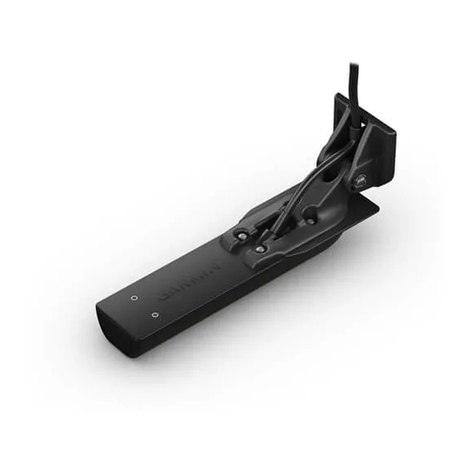
Garmin
Garmin ECHOMAP Ultra Series installation instructions

Quartz
Quartz DAPG1206A-K8115 quick start guide

Endress+Hauser
Endress+Hauser Cerabar T PMP135 operating instructions
HBM
HBM T22 Mounting instructions
Solartron Metrology
Solartron Metrology MACH 1 Series User Leaflet
S+S Regeltechnik
S+S Regeltechnik THERMASGARD RGTM 2 Operating Instructions, Mounting & Installation
