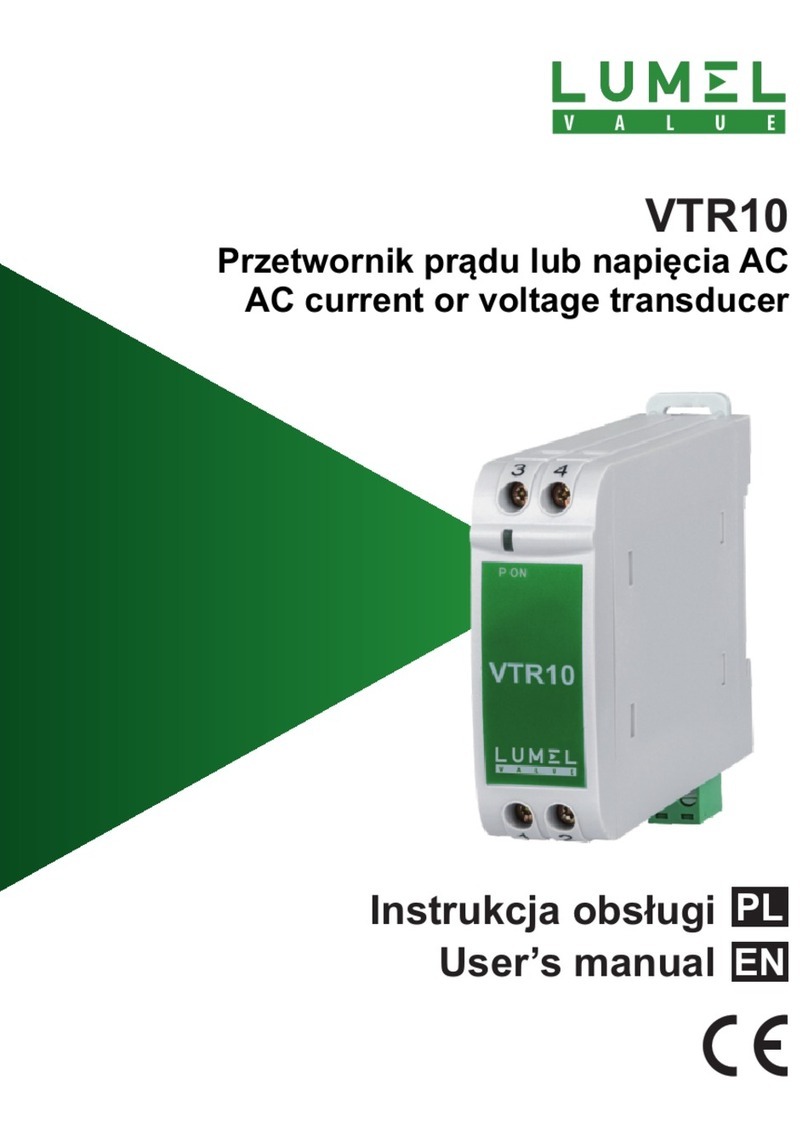
Lumel P20H Series User manual

INSTRUKCJA OBSŁUGI - SZYBKI START
Pełna wersja instrukcji dostępna na
Full version of user’s manual available at
www.lumel.com.pl
USER’S MANUAL - QUICK START PL
EN
Zeskanuj mnie
Zeskanuj kod Scan the code
PRZETWORNIK PROGRAMOWALNY
NAPIĘCIA I PRĄDU STAŁEGO
PROGRAMMABLE TRANSDUCER
OF DC CURRENT AND DC VOLTAGE SIGNALS
P20H

2
pl
1. BEZPIECZEÑSTWO U¯YTKOWANIA
W zakresie bezpieczeństwa użytkowania przetwornik odpowiada
wymaganiom normy PN-EN 61010-1.
Znaczenie symbolu: - Uwaga, grozi niebezpieczeństwo
Uwagi dotyczące bezpieczeństwa
· Montażu i instalacji połączeń elektrycznych powinna dokonać
osoba z uprawnieniami do montażu urządzeń elektrycznych.
· Przed włączeniem przetwornika należy sprawdzić poprawność
połączeń.
· Przed zdjęciem obudowy przetwornika należy wyłączyć
jego zasilanie i odłączyć obwody pomiarowe.
· Zdjęcie obudowy przetwornika w trakcie trwania umowy
gwarancyjnej powoduje jej unieważnienie.
· Urządzenie jest przeznaczone do instalowania i używania w prze-
mysłowych elektromagnetycznych warunkach środowiskowych.
· W instalacji budynku powinien być wyłącznik lub wyłącznik
automatyczny, umieszczony w pobliżu urządzenia, łatwo dostępny
dla operatora i odpowiednio oznakowany.
2. MONTA¯
2.1. Sposób mocowania
Przetworniki P20H są przystosowane do mocowania na wsporniku
szynowym 35 mm wg PN-EN 60715. Gabaryty i sposób mocowania
ilustruje rysunek 1.

3
pl
Rys 1. Gabaryty i sposób mocowania przetwornika
2.2. Schematy podłączeñ zewnêtrznych
Przetwornik posiada listwę rozłączną z zaciskami śrubowymi, które
umożliwiają przyłączenie przewodów zewnętrznych zasilania i wyjścia
o przekroju do 2,5 mm2. Podłączenia sygnałów wejściowych należy
wykonać przewodami o maksymalnej średnicy 1,5 mm2 do zacisków
śrubowych nierozłącznych.
Schematy podłączeń przedstawione są na rys. 2 i 3, na stronie 12.

4
pl
3. OBS£UGA
Po włączeniu zasilania przetwornika, dioda stanu pracy powinna się
zaświecić na chwilę na czerwono, następnie na zielono.
Rys. 4. Widok przetwornika P20H
Dioda stanu pracy przetwornika:
- dioda stanu świeci się na zielono – normalna praca;
- dioda stanu świeci się na czerwono – niewłaściwe
parametry pracy; przetwornik należy ponownie
skonfigurować;
- dioda stanu pulsuje na czerwono – brak kalibracji
lub uszkodzona pamięć nieulotna; przetwornik
należy odesłać do producenta;
Diody tylko w wykonaniu z interfejsem RS485:
- dioda RxD świeci się – odbiór danych;
- dioda TxD świeci się – nadawanie danych;
Potwierdzenie zapisu do rejestrów sygnalizowane jest przez krótkie wy-
gaszenie diody stanu. Do czasu uzyskania wymaganej liczby popraw-
nych pomiarów (zgodnie z tablicą 1) przetwarzana jest wartość średnia
arytmetyczna z dotychczasowych pomiarów. Zmierzenie wartości spoza
zakresu pomiarowego powoduje ustawienie przekroczenia i rozpoczęcie
liczenia pomiarów poprawnych od nowa. Pomiar odbywa się na zasa-
dzie okna kroczącego (moving window). Fabrycznie czas ustawiony jest
na 1s. Przy czasie uśredniania mniejszym niż 10 sekund – pojedynczy
pomiar trwa około 30 ms, natomiast powyżej trwa około 0,5 s.
Czas uśredniania 0,2s 0,4s 0,6s 0,8s 1s 3s 5s 10s 15s 20s
Ilość pomiarów
uśrednianych 6 13 20 27 34 103 172 20 30 40
Tablica 1

5
pl
W przetworniku można zaprogramować zachowanie wyjścia analogo-
wego (rejestru wartości wyjścia w wykonaniu z RS-485) przy przekro-
czeniach ustawianego zakresu pomiarowego wejścia. Ustawiane są:
wartość oczekiwana na wyjściu przy przekroczeniu dolnym (Out-d) dla
wartości poniżej przekroczenia dolnego wejścia (In-d) oraz wartość
oczekiwana na wyjściu przy przekroczeniu górnym (Out-u) dla wartości
powyżej przekroczenia górnego wejścia (In-u) – wartości zestawione
w tablicy 3 (patrz pełna wersja instrukcji obsługi, dostępna na stronie
www.lumel.com.pl).
3.1. Konfiguracja przetwornika za pomocą
programu eCon
Do konfiguracji przetworników P20H przeznaczone jest bezpłatne
oprogramowanie eCon dostępne na stronie www.lumel.com.pl.
W wykonaniu z interfejsem RS-485, przetwornik możne być konfiguro-
wany bezpośrednio przez interfejs. Przy konfiguracji przetwornika po-
przez programator PD14, należy odłączyć interfejs RS-485.
4. DANE TECHNICZNE
Zakresy pomiarowe
WEJŚCIA:
Zakres pomiaru napiêcia unipolarnego Un:
-0,5...0...100...130 V d.c.
-1...0...250...325 V d.c. rezystancja wejściowa > 2 MW
-2...0...400...630 V d.c.
Zakres pomiaru napiêcia bipolarnego Un:
-130...-100...100...130 V d.c.
-325...-250...250...325 V d.c. rezystancja wejściowa > 2 MW
-630...-400...400...630 V d.c.
Zakres pomiaru prądu bipolarnego In:
-1,3...-1,0...1,0...1,3 A d.c. rezystancja wejściowa 10 mW ±10%
-6,3...-5...5...6,3 A d.c. rezystancja wejściowa 2 mW ±10%
Wyjście analogowe prądowe 0(4)...20...22 mA; rezystancja obciążenia £ 500 W;
Wyjście analogowe napięciowe 0...10...11 V rezystancja obciążenia 500 W;
rozdzielczość 0,01% zakresu; czas reakcji wyjścia: 200 ms

6
pl
Interfejs szeregowy RS-485: adres 1...247; tryb: 8N2, 8E1, 8O1, 8N1
prędkość: 4.8, 9.6, 19.2 kbit/s; protokół transmisji: Modbus RTU;
czas odpowiedzi: 200 ms
Błąd podstawowy przetwarzania ±0,2% zakresu
Błędy dodatkowe w znamionowych warunkach użytkowania:
od zmian temperatury otoczenia (50% błędu podstawowego/10 K)
Przeciążalność długotrwała:150 % Un (we. 400 V, ± 400 V),
120% Un (we. pozostałe),120% In
Przeciążalność krótkotrwała (1 s): wejście napięcia 2 Un (<1000 V)
wejście prądowe 10 In
Znamionowe warunki użytkowania:
- napięcie zasilania : 85..253 V a.c. 40..400 Hz; 90..300 V d.c.
20..40 V a.c. 40..400 Hz; 20..60 V d.c.
- temperatura otoczenia: -20...23...60°C
- temperatura przechowywania: -25...+85°C
- wilgotność < 95% (niedopuszczalna kondensacja pary wodnej)
- pozycja pracy:dowolna
Czas uśredniania – pomiaru (programowalny): 0,2 s (domyślnie 1 s)
Czas wstępnego wygrzewania: 15 minut
Izolacja galwaniczna pomiędzy:
- zasilanie – wejście pomiarowe 3,2 kV d.c.
- zasilanie – wyjście 2 kV d.c.
- wejście pomiarowe – wyjście 3,2 kV d.c.
Zapewniony stopień ochrony wg PN-EN 60529:
obudowa: IP40; od strony zacisków: IP20
Wymiary: 22,5 x 100 x 120 mm Masa: 0,125 kg
Mocowanie: szyna 35 mm wg PN-EN 60715
Moc pobierana < 3 VA
Kompatybilność elektromagnetyczna:
– odporność na zakłócenia elektromagnetyczne wg PN-EN 61000-6-2
– emisja zakłóceń elektromagnetycznych wg PN-EN 61000-6-4
Wymagania bezpieczeństwa według normy PN-EN 61010-1:
– izolacja między obwodami: podstawowa
– kategoria instalacji III (dla wykonania 400 V – kategoria II)
– stopień zanieczyszczenia: 2
– maksymalne napięcie pracy względem ziemi:
- dla obwodu zasilania 300 V; - dla wejścia pomiarowego 600 V –
kat II (300 V – kat III) ; - dla wejścia do programowania 50 V;
- dla wyjścia 50 V
– wysokość npm < 2000 m.

7
pl
5. KOD WYKONAÑ
Kod wykonań przetwornika P20H Tablica 2
PRZETWORNIK P20H - X X X XX X X
Sygnał wejściowy:
+/- 100 V d.c............................................. 1
+/- 250 V d.c............................................. 2
+/- 400 V d.c............................................. 3
+/- 1 A d.c. ................................................ 4
+/- 5 A d.c. ................................................ 5
0...100 V d.c............................................. 6
0...250 V d.c............................................. 7
0...400 V d.c............................................. 8
Wyjście:
0...20 mA..........................................................1
4...20 mA..........................................................2
0...10 V.............................................................3
RS-485.............................................................4
Napięcie zasilania:
85..253 V a.c. 40..400 Hz; 90..300 V d.c.. ...............1
20..40 V a.c. 40..400 Hz; 20..60 V d.c. ....................2
Wykonanie:
standardowe .................................................................. 00
zaprogramowany wg wymagań klienta ..........................NS
specjalne* ......................................................................XX
Wersja językowa
polska......................................................................................P
angielska .................................................................................E
inna*........................................................................................X
Próby odbiorcze
bez wymagañ dodatkowych ............................................................0
z dodatkowym atestem Kontroli Jakoœci .........................................1
inne wymagania* ........................................................................... X
* po uzgodnieniu z producentem

EN
8
1. BASIC REQUIREMENTS, OPERATIONAL
SAFETY
In the safety service scope, the transducer meets the requirements of
the EN 61010-1 standard.
Observations concerning the operational safety:
· All operations concerning transport, installation, and commissioning
as well as maintenance, must be carried out by qualified, skilled
personnel, and national regulations for the prevention of accidents
must be observed.
· The programming of P20H transducer parameters must be carried
out after disconnecting measuring circuits.
· Before switching the transducer on, one must check the
correctness of connections to the network.
· Do not connect the transducer to the network through an
autotransformer.
· Before removing the transducer housing, one must switch the
supply off and disconnect measuring circuits. The removal of the
transducer housing during the guarantee contract period may
cause its cancellation.
· The transducer is destined to be installed and used in
electromagnetic industrial environment conditions.
· When connecting the supply, one must remember that a switch or a
circuit-breaker should be installed in the building. This switch should
be located near the device, easy accessible by the operator, and
suitably marked as an element switching the meter off.
· Non-authorized removal of the housing, inappropriate use, incorrect
installation or operation, create the risk of injury to personnel or
transducer damage.
For more detailed information, please study the User’s Manual.

EN
9
2. INSTALLATION
2.1. Fixing Way
P20H transducers are destined to be fixed on a 35 mm rail acc.
to EN 60715 standard.
Overall dimensions and the fixing way are presented on the fig. 1.
Fig. 1. Overall dimensions and fixing way of the P20H transducer
2.2. External Connection Diagrams
The transducer has a separable strip with screw terminals, which ena-
ble the connection of supply and output by 2.5 mm2 cross-section
external wires. The connection of input signals must be carried out
to inseparable screw terminals with wires of maximal 1.5 mm2 cross-
-section.
Connection diagrams are shown on fig. 2 and 3 on page 12.

EN
10
3. SERVICE
After switching the transducer on, the work state diode should light in
red for a moment, next it should light in green.
Fig. 4. View of the P20H transducer
The write confirmation in registers is signaled by a short extinction of the
state diode. Till the time to obtain the required number of correct mea-
surements (acc. to the table 1), the arithmetical mean value of measu-
rements which have been doing so far, is converted. The measurement
of values beyond the measuring range causes the overflow setting and
begins the counting of correct measurements from the beginning. The
measurement is carried out on the mowing window principle. The time
is set up on 1 s by the manufacturer.
When the averaging time is less than 10 sec – the single measurement
lasts ca 30 ms however, above 10 sec, the measurement lasts ca 0.5 sec.
Averaging time 0.2s 0.4s 0.6s 0.8s 1s 3s 5s 10s 15s 20s
Number of averaged
measurements 6 13 20 27 34 103 172 20 30 40
Table 1
Diode of the transducer work state:
- the state diode lights in green – normal work,
- the state diode lights in red – improper work
parameters; one must configure the transducer
again,
- the state diode pulsates in red – lack of calibration
or the non-volatile memory is damaged; one must
return the transducer to the manufacturer.
Diodes only in the option with RS-485 interface:
- the RxD diode lights – reception of data,
- the TxD diode lights – transmission of data.

EN
11
In the transducer , one can program the behaviour of the analog output
(the recording of the output value in the option with RS-485) at over-
flows of the set up input measuring range.
Set up values: expected on the output at lower overflow (Out-d) for a
value below the lower input overflow (In-d) and the expected value on
the output at upper overflow (Out-u) for values above the upper input
overflow (In-u) – Values are presented in the table 3 (see full version of
user’s manual, avilable at www.lumel.com.pl).
3.1. Transducer Configuration by Means of the
eCon Program
The free delivered eCon program, available in our www.lumel.com.pl
page, is destined for the P20H transducer configuration. In the option
with RS-485 interface, the transducer can be configured directly through
the interface. When configuring the transducer through the PD14 pro-
grammer, one must turn the RS-485 interface off.
4. TECHNICAL DATA
Measuring Ranges
INPUTS:
Measuring range of the unipolar Un voltage:
-0.5...0...100...130 V d.c.
-1...0...250...325 V d.c. input resistance > 2 MW
-2...0...400...630 V d.c.
Measuring range of the bipolar Un voltage:
-130...-100...100...130 V d.c.
-325...-250...250...325 V d.c. input resistance > 2 MW
-630...-400...400...630 V d.c.
Measuring range of the bipolar In current:
-1.3...-1.0...1.0...1.3 A d.c. input resistance 10 mW ±10%
-6.3...-5...5...6.3 A d.c. input resistance 2 mW ±10%
Analog output current 0(4)...20...22 mA; load resistance £ 500 W
Analog output voltage 0...10...11 V; load resistance 500 W
resolution 0.01% of the range; output reaction time: 200 ms
Serial interface RS-485: address 1...247; mode: 8N2, 8E1, 8O1, 8N1
baud rate: 4.8, 9.6, 19.2 kbit/s; transmission protocol: Modbus RTU
response time: 200 ms

EN
12
Basic conversion error: ±0.2% of the range
Additional errors in rated operating conditions:
- from ambient temperature changes (50% of the intrinsic error/10 K)
Sustained overload: 150% Un (in. 400 V, ± 400 V),120% Un (other in.),120% In
Short duration overload (1 s): voltage input 2 Un (<1000 V); current
input 10 In
Rated operating conditions:
- supply voltage: 85..253 V a.c. 40..400 Hz; 90..300 V d.c.;
20..40 V a.c. 40..400 Hz; 20..60 V d.c.
- ambient temperature: -20...23...60°C
- storage temperature: -25...+85°C
- humidity < 95% (inadmissible vapour condensation)
- work position: any
Averaging time (programmable): 0,2 s (default 1 s)
Preheating time :15 minutes
Galvanic isolation between:
- supply – measuring input 3.2 kV d.c.
- supply – output 2 kV d.c.
- measuring input – output 3.2 kV d.c.
Ensured protection grade acc. to EN 60529:
casing: IP 40; from the terminal side: IP 20
Overall dimensions: 22.5 x 100 x 120 mm Weight: 0.125 kg
Fixing: on a 35 mm rail acc. EN 60715
Input power < 3 VA
Electromagnetic compatibility:
– noise immunity acc. to EN 61000-6-2
– noise emissions acc. to EN 61000-6-4
Safety requirements acc. to EN 61010 -1 standard:
– isolation between circuits: basic
– installation category: III ( for the 400 V option – category II)
– pollution grade: 2
– maximal phase-to-earth working voltage:
- for the supply circuit: 300 V
- for the measuring input: 600 V - category II, (300 V – cat. III)
- for the programming input: 50 V
- for output: 50 V
– altitude above sea level < 2000 m.
EN
13
5. ORDERING CODES
Table 2.
TRANSDUCER P20H - X X X XX X X
Input signal:
+/- 100 V d.c............................................. 1
+/- 250 V d.c............................................. 2
+/- 400 V d.c............................................. 3
+/- 1 A d.c. ................................................ 4
+/- 5 A d.c. ................................................ 5
0...100 V d.c............................................. 6
0...250 V d.c............................................. 7
0...400 V d.c............................................. 8
Output:
0...20 mA..........................................................1
4...20 mA..........................................................2
0...10 V.............................................................3
RS-485.............................................................4
Supply:
85..253 V a.c. 40..400 Hz; 90..300 V d.c. ................1
20..40 V a.c. 40..400 Hz; 20..60 V d.c. ....................2
Version:
standard ........................................................................ 00
non-standard settings.....................................................NS
custom-made* ................................................................XX
Language:
Polish ......................................................................................P
English ....................................................................................E
other*.......................................................................................X
Acceptance Tests
without extra quality requirements ..................................................0
with an extra quality inspection certificate.......................................1
acc. to customer’s requirements*................................................... X
* after agreeing with the Manufacturer

pl EN
14
schematy podłączeń
electrical connections
Rys. 2. Podłączenia elektryczne wejœæ przetwornika P20H:
a) prądowe b) napiêciowe
Fig. 2. Electrical connections of P20H transducer inputs.
a) voltage b) current

PL EN
15
Rys. 3. Podłączenia elektryczne zasilania i wyjœcia P20H:
a) z wyjœciem analogowym b) z interfejsem
Fig. 3. Electrical connections of the P20U transducer
supply and output:a) with analog output, b) with RS-485 interface

P20H-07A_09A
Informacja techniczna:
tel.: (68) 45 75 306, 45 75 180, 45 75 260
e-mail: [email protected]
Realizacja zamówień:
tel.: (68) 45 75 207, 45 75 209, 45 75 218, 45 75 341
fax.: (68) 32 55 650
LUMEL S.A.
ul. Sulechowska 1, 65-022 Zielona Góra, Poland
tel.: +48 68 45 75 100, fax +48 68 45 75 508
www.lumel.com.pl
Pracownia systemów automatyki:
tel.: (68) 45 75 228, 45 75 117
Wzorcowanie:
tel.: (68) 45 75 161
e-mail: [email protected]
Export department:
tel.: (+48 68) 45 75 139, 45 75 233, 45 75 321,
45 75 386, 45 75 353
fax.: (+48 68) 32 54 091
e-mail: expor[email protected]om.pl
Calibration & Attestation:
tel.: (68) 45 75 161
e-mail: [email protected]
Table of contents
Languages:
Other Lumel Transducer manuals
Popular Transducer manuals by other brands

turck
turck HART IM33-11-Hi/24VDC Series quick start guide

DFE
DFE TrueTension TI17C instruction manual

MKS
MKS Baratron 722B instruction manual

Shark
Shark 100T quick start guide

Barcus-Berry
Barcus-Berry 3110 installation guide

S+S Regeltechnik
S+S Regeltechnik THERMASGARD HFTM-VA Operating Instructions, Mounting & Installation