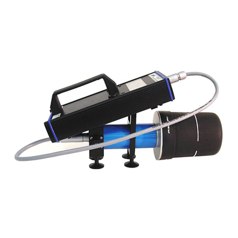
Attonic AD-TM Series User manual

Digital Torque Meter
Operation Manual
AD-TM Series
ATTONIC CO., LTD.

・After reading this manual, be sure to keep it in a place where the users can refer to it whenever necessary.
WARNING
1-16.Our products use nickel-hydrogen rechargeable batteries. It is a recycled resource.
1-18.If a situation other than the contents of this manual occurs, stop using this meter immediately and contact us.
substances.
If you need to replace the battery, please leave it to us.
1-17.Turn off the power of all devices before connecting to an external device.
Failure to do so may result in electric shock or equipment damage.
malfunction.
・Do not use a DC power supply or engine generator. It may cause a malfunction or fire.
・Recharge the battery in a well-ventilated place. Do not cover it with any sheet like a cloth while charging.
1-14.Be careful of electric shock. Do not touch the power plug with wet hands. It may result in electric shock.
1-15.Do not throw the battery (built into the main body) into a fire. The battery will explode or release harmful
This meter is a precision equipment, do not disassemble it.
If equipment malfunctions occur due to excessive impact or vibration, it will not only fail to perform adequately,
but also cause accidents and injuries.
1-13.Charge it properly.
・
Use only the supplied AC adaptor for charging. Using an AC adaptor other than the one supplied may cause a
1-11.Ask your dealer for repairs.
・Do not modify this meter.
・Be sure to contact the dealer where you purchased this meter for repairs. If it is repaired by a person without
repair knowledge or skills, it will not only fail to perform adequately, but also cause accidents and injuries.
1-12.Do not disassemble this meter, or subject it to strong impact or vibration.
function.
・Check if there are any abnormalities in all parts that affect the use.
・ Replace the parts according to this manual.
1-10.Use the specified accessories, appropriate bits and sockets. Do not use any accessories or attachments not
described in this manual.
In the following cases, switch off the main body and disconnect the plug from the power supply.
・When not used or charged.
・When other danger is predictable.
1-9.Check if there are any damaged parts.
・Before use, checkitthoroughly forany damage, and ensure that it works normally and performs the designated
cords out from the outlet or connector.
1-8.For safe and efficient operation
・Check the main body and attachments, etc. regularly, and use the ones that are not deformed and worn.
・
Follow the operation manual when replacing accessories.
・Check the cords and extension cords regularly, and replace them if they are damaged.
・Use in a place where the temperature is constant (about 23 ℃) , if possible.
・Make sure the workplace is adequately lit.
・Do not use or charge in a place with flammable liquid or gas.
1-6.Keep children away. Only the operator is permitted to enter the workplace.
1-7.Don not handle the cords roughly. Do not hold the cords to carry the main body with the cords attached, or pull the
1-2.Do not use this meter to measure an impact type fastening tool.
1-3.Make sure the main body is firmly secured so that it will not swing around when measuring.
1-4.Always keep the workplace clean. A cluttered place or workbench could cause an accident.
1-5.Also consider the surrounding conditions of the workplace.
・Do not use in a place with high temperatures, high humidity, direct sunlight, or a lot of dust or dirt.
1.Safety precautions
・To prevent accidents such as fire, electric shock and injury, be sure to observe the following "Safety Precautions".
・Read all of the "Safety Precautions" carefully before using this meter, and follow the instructions to use it correctly.
1-1.Do not apply a torque that exceeds the allowable load. If a torque exceeding the allowable range is applied,
the detector may be damaged, resulting in an accident or injury.
!

2.Precautions for storage and use
charge it.
(The above information is common to almost all of our products, however, may not be fully applied to some products.)
2-7.Do not use in an environment of oil, dust, high temperature and humidity.
2-8.After use, store it in a safe place so that no load is applied to the detection shaft.
2-9.Do not use organic solvents, etc. when cleaning this meter.
2-10.If the product is left unused for a long time, the battery may deteriorate and become unable to recharge.
Turn on the power of this meter once a month to check the charging status, and if charging is required, be sure to fully
・Use your common sense.
・Do not use it when you are tired.
2-5.Do not apply large twisting forces, lateral bending forces, and forces that exceed a tolerance to the detection shaft,
otherwise, the detector will be damaged.
2-6.Do not use this meter for any purpose other than measurement.
operation.
2-3.Do not work in an unnatural working posture. Keep proper footing and balance at all times.
2-4.Do not be negligent in using this meter, and handle it with great caution.
・When using this meter, operate it very carefully while paying full attention to the method of handling and operation,
the surrounding conditions and so on.
2-1.Store this meter properly when it’s not in use. Store in a dry place, high place or locked place out of the reach of
children. Also, please use the original packing box that contained this meter when transporting.
2-2.Wear proper clothes. Do not wear loose clothing, necklaces, or other jewelry as they may interfere with the
!
⑨Charge Pilot Lamp
⑩USB Connector (Mini USB Type-B)
⑥Detection shaft (Drive width 17
socket)
⑦Display
⑧DC IN (Power Jack)
③FUN Switch ⑬Rubber Foot
④RES Switch ⑭Mounting hole
⑤
Mounting screws for the main
body (M5 2places)
3.Parts names
3-1.The name and application area of parts
①POW Switch ⑪I/O Socket
②DAT Switch ⑫ANALOG Output Jack
①② ③ ④
⑤
⑥
⑦
⑧⑨ ⑩ ⑫
・
⑪⑬
⑭

3-2.Attachments
■AD-TM1/5
TC-2
(M3 Screw/#2)
TSS-5
(M4 Screw/#2+With Spring)
* Spare screw:
2 screws each are attached.
■AD-TM10
TC-3
(M4 Screw/#2)
TSS-10
(M4 Screw/#2+With Spring)
* Spare screw:
2 screws each are attached.
■AD-TM50
TC-6
(M5 Screw/#2)
TSS-30
(M6 Screw/#3+With Spring)
* Spare screw:
2 screws each are attached.
■AD-TM100/200
TC-4
(M6 Screw/#3)
TSS-30
(M6 Screw/#3+With Spring)
* Spare screw:
2 screws each are attached.

4.Specifications
TM1 TM5 TM10 TM50 TM100 TM200
±1.000
~
±10.00
N
・
cm
±5.00
~
±50.00
N
・
cm
±10.00
~
±100.0
N
・
c
m
±0.500
~
±5.000
N
・
m
±1.000
~
±10.00
N
・
m
±2.00
~
±20.00
N
・
m
±100.0
~
±1000
gf
・
cm
±0.500
~
±5.000
kgf
・
cm
±1.000
~
±10.00
kgf
・
cm
±5.00
~
±50.00
kgf
・
cm
±10.00
~
±100.0
kgf
・
cm
±20.0
~
±200.0
kgf
・
cm
±0.100
~
±1.000
lbf
・
in
±0.500
~
±5.000
lbf
・
in
±1.000
~
±10.00
lbf
・
in
±5.00
~
±50.00
lbf
・
in
±10.00
~
±100.0
lbf
・
in
±20.0
~
±200.0
lbf
・
in
PEAK
TRACK
Right peak / Left peak(P-P)
Accessories
AD-TM1
AD-TM5
AD-TM10
AD-TM50
AD-TM100
AD-TM200
TSS-10 / TC-3
TSS-30 / TC-6
Measurement
mode
Measurement range
TSS-30 / TC-4
Net weight About 2.4kg
Attachments Others
TSS-5 / TC-2
AC adaptor(AD-20)
USB cable (AD-USB-1.5)
Data output ASCII format (Baud rate: 19200)
Dedicated charger IN:AC100V~240V OUT:DC9V
Dimension About172(L)×210(W)×55(75 with the measuring socket included) (H)
Usage time About 12 hours in continuous use
Battery life Rechargeable more than 300 times (depending on usage conditions)
Auto power off Power off after being left for 10 min.
(Measurement without any time limit is also available)
Battery-powered Rechargeable Ni-MH Battery 1.2v×4cells (1650mAh)
Measurement unit Switchable 3 units: N・m(N・cm)/kgf・cm(gf・cm)/lbf・in
Charging time About 3 hours
Measurement direction + : Right rotation, - : Left rotation
Hold the maximum torque
The display changes as the torque value changes. Used for zero adjustment, etc.
Hold the left and right peak values.
Model (AD-)
Accuracy ±0.5% FS
Display 4 Digits LCD

* If you need to recharge the battery immediately, use the supplied AC adaptor to recharge the battery.
:
In good condition with more than 50% power remained.
:
Less than 50% remaining. A status that requires caution. (still usable.)
・
When measuring by holding this meter in your hand, please be careful about the surroundings.
・
When fixing this meter, use a tool appropriate to fixing it firmly in 2 places with M5 screws.
* When fixing to a device, etc., check the fixing method and fix this meter firmly with a tool, etc.
5-3.Attachment installation
・
Use the supplied attachments according to the measurement conditions.
* If you cannot measure with the supplied attachments, please contact us.
We also manufacture special attachments.
* Do not use the attachments from other suppliers. They may cause a malfunction or injury.
Cautions
5-2.Mounting
・When the power is turned off, the stored data (N:〇〇〇) will be cleared to zero.
5.Preparation for measurement
5-1.Check the charging status
Be sure to check the charging status (battery icon) before using this meter.
* The sign on the upper left of the screen is the battery icon.
:Recharging is required immediately.
Battery icon

* Once set, these settings are memorized
unless the battery runs out or the
setting is changed.
* The display becomes 0 (zero) when
"RES" switch is pressed.
Exit when the screen goes off.
Set other functions.
Right rotation test.
Left rotation test.
Long press the "POW" switch
when the test is finished.
6.Basic flow of usage
Power ON
"POW" switch ON
Set measurement mode.
Set measurement unit.

* The set data will "not" be saved. * The set data will be saved.
maximum measured value of each model.
PP
:
The screen will be displayed in two sections.
Centering on zero, the upper section is the + peak holding and the
0.2% or more of the maximum measured value of each model.
* The unit symbol changes depending on the model.
PEAK:Hold and display the maximum absolute value during
measurement. Hold a torque value from 0.2% or more of the
lower section is the - peak holding. Both hold a torque value from
* Short press the "FUN" switch to confirm the setting. Next is the setting for changing measuring unit.
7-2.Change measuring unit (Initial Unit:N・m or N・cm)
・You can change the measurement unit.
Switchable 3 units: N・m(N・cm), kgf・cm(gf・cm), lbf・in
* Short press the "FUN" switch to confirm the setting. Next is the setting for comparator HI.
* "DATA SAVE?" screen appears when you long press the "FUN" switch anywhere in the settings.
Select "OK" or "CANCEL" and press the "POW" switch to complete the setting.
7-1.Set measurement mode (Initial Setting: TRACK)
・You can switch the measurement mode.
Switch between TRACK mode and PEAK mode by pressing the "DAT" switch.
The one with a black background is the one selected.
TRACK: The torque value applied to the detector is displayed as it is.
It is used to view measurements that change constantly.
7.Function settings and descriptions
To set each function, long press the "FUN" switch until you hear a beep.
"FUN" will be displayed at the top of the screen when the meter becomes the function setting mode.
If "FUN" is not displayed, long press the "FUN" switch again until you hear a beep.
* Please note that it is set longer so that the measurement mode will not be switched due to a malfunction
during measurement.
To complete the setting, long press the "FUN" switch again until you hear a beep.
The screen will look as follows.
Select "OK" if you want to save the data, or "CANCEL" if you don't, and press the "POW" switch.
"POW" Switch "POW" Switch
"DAT" Switch
"POW" Switch
"DAT" Switch
"DAT" Switch
The display changes
every time the "DAT"
switch is pressed.

* Short press the "FUN" switch to confirm the setting. Next is the setting for comparator LO.
setting value (- side) is exceeded. After that, even if the HI peak value is exceeded, a long intermittent sound
continues.
* A long intermittent sound will be heard if the LO setting value (- side) is exceeded, and a short one if the HI
setting value (+ side) is exceeded. After that, even if the LO peak value is exceeded, there is still a short
intermittent sound.
* The position of the decimal point varies with each unit and each model.
* For models that increase in digits, the maximum setting value is 9999.
For example: When the unit is N・m in AD-TM100, the settable maximum value is 9.999(N・m).
* The setting value returns 0 when the mode is changed.
* The setting value should be entered as an absolute value (regardless of whether it is positive or negative).
* It returns to the beginning when the "DAT" switch is pressed 4 times.
〇PP Mode
・You can change the setting value on the + side (upper section) of comparator.
For example, if you set the point of + side (HI) to 1.00N・m and the point of - side (LO) to -0.50N・m, and
gradually apply force to the + side from 0.00N・m, the display of the upper section will be changed, and
when the force exceeds 1.00N・m, a short intermittent sound will be heard.
* The setting value should be entered as the value of + side instead of an absolute value.
* A short intermittent sound will be heard if the HI setting value (+ side) is exceeded, and a long one if the LO
7-3.Set comparator HI (Initial value: 0000)
〇TRACK / PEAK Mode
・You can change the HI side setting value of the comparator.
A comparator is a comparison with a set value.
For example, if you set the point of high value (HI) to 1.00N・m and the point of low value (LO) to 0.50N・m
and gradually apply force from 0.00N・m, LO will be indicated with a long intermittent sound at first,
but the display and buzzer sound will disappear when the force exceeds 0.50N・m.
When the force exceeds 1.00N・m, HI will be indicated and a short intermittent sound will be heard.
* When the HI or LO value is set (non-zero), the external output is also outputted in conjunction with it.
"POW" Switch
"POW" Switch
"DAT" Switch "DAT" Switch
This digit blinks.
The digit shifts to the
left by one place
every time the
"DAT" switch is
pressed.
This digit blinks when
the "DAT" switch is
pressed 3 times.
"DAT" Switch
The value will increase if the
"POW" switch is pressed
while this digit is blinking.
"POW" Switch
"9" is indicated when the "POW"
switch is pressed 9 times.
It returns “0” when the "POW" switch
is pressed again.

・
It is a function to warn the users to avoid accidental damage to the torque sensor.
* Short press the "FUN" switch to confirm the setting. Next is the setting for screen update rate.
7-6.Set screen update rate UD (Initial value: 20)
・You can set the screen update rate (switching speed).
By decreasing the value, you can check the changing values in more real time.
However, if the update rate is too fast, the values will change quickly and it may be difficult to see.
* Update rate is in seconds. If the display value is 20, the display will be updated every 20 seconds.
* There are 4 types of settings: 20, 10, 5, and 2 seconds.
* Short press the "FUN" switch to confirm the setting. Next is the setting for flipping screen.
* For models that increase in digits, the maximum setting value is 9999.
For example: When the unit is N・m in AD-TM100, the settable maximum value is -9.999(N・m).
* The setting value returns 0 when the mode is changed.
* Short press the "FUN" switch to confirm the setting. Next is the setting for overload.
7-5.Set overload OV (Initial value: 120)
For example, when performing a torque test, it can display a warning at 80% of full scale and output a signal
to stop the test so that the sensor is not damaged by applying excessive force accidentally.
* The setting can be set by 10% up to 120%.
* The setting value should be entered as the value of - side instead of a absolute value.
* A short intermittent sound will be heard if the HI setting value (+ side) is exceeded, and a long one if the LO
setting value (- side) is exceeded. After that, even if the HI peak value is exceeded, there is still a long
intermittent sound.
* A long intermittent sound will be heard if the LO setting value (- side) is exceeded, and a short one if the HI
setting value (+ side) is exceeded. After that, even if the LO peak value is exceeded, there is still a short
intermittent sound.
* The position of the decimal point varies with each unit and each model.
〇PP Mode
・You can change the setting value on the - side (lower section) of comparator.
For example, if you set the point of + side (HI) to 1.00 N・m and the point of - side (LO) to -0.50 N・m, and
gradually apply force to the - side from 0.00N・m, the display of the lower section will be changed, and
when the force exceeds -0.50N・m, a short intermittent sound will be heard.
7-4.Set comparator LO (Initial value: 0000)
〇TRACK / PEACK Mode
・You can change the setting value on the LO side of comparator.
・Refer to 7-3. Set comparator HI for the function description, setting method, and operation method.
"POW" Switch
"POW" Switch
"POW" Switch
"POW" Switch
Increase by 10
every time the
"POW" switch is
pressed.
"POW" Switch
"POW" Switch
"POW" Switch
"POW" Switch

* Short press the "FUN" switch to confirm the setting. Next is the setting for the minimum digit display.
7-10.Set the minimum digit display MD (Initial Setting: ON)
・Set whether to display the minimum digit or not.
The display looks more stable when the minimum digit is not displayed (OFF).
* The display range varies depending on the model. For the display range, refer to the display range table.
* You can switch ON / OFF repeatedly by pressing the "DAT" switch.
* Short press the "FUN" switch to confirm the setting. Next is the setting for buzzer.
* You can switch ON / OFF repeatedly by pressing the "DAT" switch.
* Short press the "FUN" switch to confirm the setting. Next is the setting for auto reset.
7-9.Set auto reset AC (Initial Setting : OFF)
・It is a setting to automatically reset after 3 seconds when the load torque disappears.
You don't have to press the reset button every time you run the same test over and over again.
* When reset, the data will be saved automatically.
* Work efficiency will increase when used in combination with printer output.
* You can switch ON / OFF repeatedly by pressing the "DAT" switch.
・It is a setting to flip the screen.
For example, when measuring with the detection shaft facing up, the values are displayed upside-down and
difficult to read, but by turning on this setting, the values can be read as they are.
* You can switch ON / OFF repeatedly by pressing the "DAT" switch.
* Short press the "FUN" switch to confirm the setting. Next is the setting for auto power off.
7-8.Set auto power off AF (Initial Setting: ON)
・It is a setting to turn off the power if no operation is performed for 10 minutes.
Turn this setting OFF if you want to use the meter for a long time.
The measurement will remain until the battery runs out.
7-7.Set flipping screen DP (Initial
Setting
: OFF)
The display changes every
time the "DAT" switch is
pressed.
The display changes every
time the "DAT" switch is
pressed.
The display changes every
time the "DAT" switch is
pressed.
The display changes every
time the "DAT" switch is
pressed.

* You can switch ON / OFF repeatedly by pressing the "DAT" switch.
* Short press the "FUN" switch to confirm the setting. Next is the setting for reset to Initial Setting.
7-12.Set backlight BL (Initial Setting: OFF)
・Turn the backlight ON / OFF.
Turn on the backlight when using in a dark place. The backlight will brighten the screen and make it easier to see.
* When the backlight is ON, it consumes a lot of battery power and shortens the usage time.
* You can switch ON / OFF repeatedly by pressing the "DAT" switch.
* Short press the "FUN" switch to confirm the setting. Next is the setting for polarity.
7-13.Set polarity IN (Initial Setting: OFF)
・When OFF, right rotation is set to + and left rotation is set to -, but when ON, right rotation is set to - and left
rotation is set to +.
Comparator HI Intermittent sound
(fast)
Remove the load and press "RES"
switch.
Comparator LO Intermittent sound
(slow)
Remove the load and press "RES"
switch.
Switch operation
Short sound
The buzzer gives a warning during the main body operation or various settings.
When the buzzer sound is annoying, you can turn it off to silence the sound.
* You can switch ON / OFF repeatedly by pressing the "DAT" switch.
* Short press the "FUN" switch to confirm the setting. Next is the setting for backlight.
* The following is a list of buzzer sounds.
Action
Sound The way to stop buzzer
Overload Continuous sound Remove the load and press "RES"
switch.
7-11.Set buzzer
BP
(Initial
Setting
: ON)
・Set whether to sound the buzzer or not.
The display changes every
time the "DAT" switch is
pressed.
The display changes every
time the "DAT" switch is
pressed.
The display changes every
time the "DAT" switch is
pressed.

7-14 Reset to Initial Setting IV (Initial Value:OFF
)
・
Reset all setting into Initial Value
※
Change ON/OFF by pressing "DAT" switch
※
Short p
ress the "FUN" switch for confirm & Move to Printer Output Setting
※
All setting will be changed into initial value after completing the setting.
List of Initial Value
MARK
UN
HI
LO
OV
UD
DP
AF
AC
MD
BP
BL
IN
IV
PO
*When “TRACK” mode is chosen, it cannot be printed out even though Printer output setting is ON.
*When Printer Output Setting is ON & “PEAK” or “PP” mode is chosen, the letter “PO” is showed at the lower left
part of display.
(This letter “PO” is not shown when “TRACK” mode is chosen)
When you push Reset switch at this moment, the main unit will not be controlled while few seconds until the
display is reset because the main unit is in the mode for searching printer.
Please choose this setting “OFF” when you do not use printer.
Returns to the first setting(7-1. Measurement mode).
7-9
7-10
7-11
7-12
7-13
7-14
7-15
Page to refer
7-1
7-2
7-3
7-4
7-5
7-6
7-7
7-8
7-15.Set printer output PO (Initial Setting: OFF
)
・Set whether to output to the printer or not.
When the printer output setting is ON, the display data can be outputted to the printer by pressing the "RES"
switch.
* Use Mitutoyo's Digimatic Mini Processor DP-1VA as the printer.
* You can switch ON / OFF repeatedly by pressing the "DAT" switch.
* Short press the "FUN" switch to confirm the setting.
Initial Setting
TRACK
N・m or N・cm
0
0
120
10
OFF
ON
OFF
ON
ON
OFF
OFF
OFF
FUNCTION NAME
Set measurement mode
Change measuring unit
Set comparator HI
Set comparator LO
Set overload OV
Set screen update rate UD
Set flipping screen DP
Set auto power off AF
Set auto reset AC
Set printer output PO
or
Set the minimum digit display MD
Set buzzer BP
Set backlight BL
Set polarity IN
Reset to Initial Setting IV
OFF
The display changes every
time the "DAT" switch is
pressed.
The display changes every
time the "DAT" switch is
pressed.

* The larger the number of N:
〇〇〇
, the newer the data.
* When the number is more than N
:
999 (over 1000 data), the old data will be overwritten.
* Short press the "FUN" switch to move to the batch transfer function.
* Long press the "FUN" switch to return to the measurement mode.
1000 data from N:000 to N:999 can be imported.
The "MO" in the upper right conner of the screen disappears and the meter becomes measurement mode.
8-1.Display history data
You can check the stored data.
The N:〇〇〇 at the top center of the screen is the number of imported data.
When the display shifts to history check screen, "MO" will be displayed in the upper right corner of the screen.
If "MO" is not displayed, long press the "DAT" switch again until you hear a beep.
* Please note that it is set longer so that the measurement mode will not be switched due to a malfunction
during measurement.
To complete the setting, long press the "FUN" switch again until you hear a beep.
8.Checking method on history data and function description
Measure in peak mode and press the "RES" switch to save the value at that time.
You can go back and check the history of those values.
■Check history data
To check history data, long press the "DAT" switch until you hear a beep.
"DAT" switch
"DAT" switch
"POW" switch
N:〇〇〇 increases every
time the "POW" switch is
pressed.
N:〇〇〇 decreases every
time the "DAT" switch is
pressed.
"POW" switch
"POW" switch
"POW" switch
"DAT" switch
"DAT" switch

8-2.Batch transfer
When this "N: 020" is set, 20 data will be transferred in a batch.
8-3.All clear
* Long press the "FUN" switch to return to measurement mode.
Delete all the stored data.
* For example, if the number of stored data is 20, "N:〇〇〇" at the top center of the screen will be "N: 020".
* The value of "〇〇〇" in "N: 〇〇〇" cannot be changed.
Transfer all the stored data to a PC, etc. in a batch.
* For example, if the number of stored data is 20, "N:〇〇〇" at the top center of the screen will be "N: 020".
* The value of "〇〇〇" in "N: 〇〇〇" cannot be changed.
* Short press the "FUN" switch to move to all clear function.
* Short press the "FUN" switch to move to history data display function.
The display changes
every time the "DAT"
switch is pressed.
Press the "POW" switch to
transfer the data.
* This screen
appears when
the data transfer
is finished.
To all clear
function
"FUN" switch
The
display
changes every
time the "DAT" switch is
pressed.
Press the "POW" switch
to delete the data.
* This screen
appears when the
data deletion is
finished.
To history data display
function
"FUN" switch
If the USB data transmission
fails and then press the "POW"
switch, the screen display will change
to "CANCEL".

The MAX/MIN/AVE values of all stored data can be displayed.
* Long press the "FUN" switch to return to the measurement mode.
* The data is displayed in absolute value.
upper right corner of the screen.
If "AV" is not displayed, short press the "DAT" switch again.
To complete the setting, long press the "FUN" switch until you hear a beep.
The "AV" display in the upper right corner of the screen disappears and the meter becomes measurement mode.
9-1.MAX/MIN/AVE values
9.Checking method on MAX/MIN/AVE values and function description
You can check the MAX/MIN/AVE values of all stored data.
■Check MAX/MIN/AVE values
Short press the "DAT" switch in peak mode (PE) to check MAX/MIN/AVE values.
When the display shifts to the check screen for MAX/MIN/AVE values, "AV" will be displayed in the
MAX:maximum value
MIN:minimum value
AVE:average value
"DAT" switch
"DAT" switch
"DAT" switch

10.I/O connector
■
The pin layout of I/O connector
Pin No. Name I/O
1 VBO -
2 POW I
3 COP I
4 INT I
5 RES I
7 OK O
9 OV O
10 CLK -
11 DAT -
12 RDY -
13 REQ -
14 GND -
■
Circuit diagram
Power supply circuit
* External supply voltage: max. DC24V
Input circuit Output circuit
* Max. DC24V 20mA * Max. DC24V 50mA
Digimatic REQ
External ground (board ground is also possible)
* Pin No.10~13 are for Mitutoyo's printer output only.
Mitutoyo's Digimatic Mini Processor (DP-1VA)
6
8
HI
LO
O
O(ON when the display value of - side is greater than or equal to the setting value in PP mode. )
ON when it is overloaded.
Digimatic CLK
Digimatic DAT
Digimatic RDY
RES switch
ON when the value is greater than or equal to comparator HI.
(ON when the display value of + side is greater than or equal to the setting value in PP mode. )
ON when it is OK.
ON when the value is less than or equal to comparator LO.
Function
Power input (It is also possible to output battery voltage from the circuit board.)
POW switch
Continuous output
One-shot output (output the value to the PC when the signal is LO)
1
13
2
14
External
voltage
External
voltage
Battery
voltage
Battery
voltage
Load

11.Analog output
The analog output provides an analog voltage proportional to the sensor signal.
■Analog circuit diagram
* Voltage: ± 2V to the max.
* Please use an analog earphone jack (with shield) for connection to external devices.
* Do not short circuit. It may cause a malfunction.
* Do not apply voltage from outside.
12.Digimatic communication connection
(
Printer
(
DP-1VA
))
* The cable is available as an option.
The measured values can be printed out by Mitutoyo's Digimatic Mini Processor (DP-1VA).
External devices
F.G. shielded wire
Digital Torque Meter
Dedicated cable
Mitutoyo Co., Ltd.
Digimatic
Mini Processor
DP-1VA

13.Data transmission settings
You can change the settings and the output data via USB.
■
Data transmission protocol
Stop bit: 1 bit
Parity bit: None
Delimiter: CR + LF
Flow control: None
■
Transmission and reception code list
"Command"
Contents
Cautions
Example (all with CR+LF attached at the end)
The signal is transmitted at 2KHz.
(The output continues until the "STOP" signal
is received.)
"STOP"
Continuous transmission stop
STOP
"MEMORY"
Transmit all stored data
MEMORY
"CLEAR"
ALL CLEAR
Delete the stored data
CLEAR
"FUNC_MODE"
FUNC Switching
Please send first when you change the
settings.
FUNC_MODE
"TRACK"
Change to TRACK
TRACK
"PEAK"
Change to PEAK
PEAK
"PP"
Change to PP
PP
"GF"
Change to gram unit system
GF
"NEWTON"
Change to Newton unit system
NEWTON
"POND"
Change to pound unit system
POND
Error if more than the settable value.
Cannot exceed the maximum value.
Error if more than the settable value.
Cannot exceed the comparator HI setting.
"OVER:" Overload setting value
Error if not a settable value
.
10
~
120 in 10
increments
OVER:100
"LCD_LATE:"
Screen update rate
Error if not a settable value
.
20,10,5,2 only
LCD_LATE:2
"LCD_FLIPPED:"
Flip the screen vertically
"ON": permission, "OFF": none
LCD_FLIPPED:ON
"POWER_OFF:"
Auto power off
"ON": permission, "OFF": none
POWER_OFF:ON
"AUTO_CLEAR:"
ALL CLEAR
"ON": permission, "OFF": none
AUTO_CLEAR:ON
"MIN_DIGIT:"
Minimum digit display
"ON": permission, "OFF": none
MIN_DIGIT:OFF
"BUZZ:"
Buzzer permission
"ON": permission, "OFF": none
BUZZ:OFF
"BACK_LIGHT:"
Backlight permission
"ON": permission, "OFF": none
BACK_LIGHT:ON
"GAIN_INVERT:"
Plus / minus inversion
"ON": permission, "OFF": none
GAIN_INVERT:OFF
"INIT_VALUE:" Reset to initial setting
"ON": permission, "OFF": none
INIT_VALUE:
"PRINTER:"
Printer permission
"ON": permission, "OFF": none
PRINTER:ON
"SET_SAVE"
Save change value
Send it at last to save values.
SET_SAVE
"CANCEL"
Cancel the change
Send it at last to cancel the change.
CANCEL
"VALUE_READ"
Read current value
Read current value. COM_OK is not returned.
VALUE_READ
* Receive a reply message of "COM_OK!!", if the command input is correct.
* Receive a reply message of "COM_ERR!!", if the command input is incorrect.
* Be sure to send "SET_SAVE" after changing the settings.
Otherwise,the settings will not be enabled and the display
will not return to the measurement screen, either.
* Once set, it cannot be returned to the original value.
* An example of send command input
Set the comparator HI to 10.0.
Command: setting value CR + LF
COMP_HI: 10.0 CR+LF
"STAT"
"CMP_HI:"
"CMP_LO:"
Continuous transmission
Comparator HI setting
Comparator LO setting
STAT
CMP_HI:2000
CMP_LO:1000
Baud rate: 19200
Character length: 8 bits
This manual suits for next models
6
Table of contents
Other Attonic Measuring Instrument manuals
Popular Measuring Instrument manuals by other brands

Ashcroft
Ashcroft 50 HPS Installation and maintenance instructions

Agilent Technologies
Agilent Technologies ESA Series User's and service guide

Konica Minolta
Konica Minolta AeroDR System Operation manual

PCB Piezotronics
PCB Piezotronics J357B03 Installation and operating manual

intellic
intellic EFAS-4.8 user guide

Endress+Hauser
Endress+Hauser Prolevel FMC 662 Installation and operating instructions