Vision Technology The View CCTV User manual

Made in the USA
TheViewTM CCTV
Owners Manual &
Set-up Instructions

2
TABLE of CONTENTS
Important Information 3
Introduction 4
Unpacking 4
Set-up 5-12
Close Down 13-15
Operating Controls Diagram 16
Description of Controls 16-17
Operating your View 18
Care and Maintenance 19
Warranty & Service Informa-
tion
19

3
Important Information
Thank you for choosing the VIEWTM
portable video magnification system. The
VIEW is a quality portable in-line system
with a movable camera, distance, close-up
and mirror image viewing capability.
Should your VIEW require service, refer to
the Warranty Information section in this
manual.
Caution: Do not remove the cover on the
monitor or camera. There are no user
serviceable parts inside. Any changes or
modifications not expressly approved or
performed by Vision Technology, Inc. could
void the user’s warranty.
Record the Serial number and date pur-
chased: Model vt 3315
Serial Number: __________
Date Purchased _____/_____/2006_
Please return the registration card in the
mail (no postage required) or call 1-800-
560-7226 to register your View with the
manufacturer and validate the warranty.

4
Introduction
Although your new system is very simple
to use, it is very important that you read
the instructions in this guide very carefully.
This step by step manual is arranged in the
way we anticipate you will operate your
new system.
Should you require assistance with set-up
or a service issue please contact our client
care department Monday—Friday 8:30am -
4:30 pm CST at 1-800-560-7226. Our
service department is here to provide
courteous and knowledgeable responses to
your inquiries.
Unpacking
Carefully remove the unit from the carton.
Save all of the packing materials,
including shipping carton(s). They will
come in handy if you have to store or ship
your system. After unpacking, use the fol-
lowing checklist to make sure you have
each of the listed items:

5
Checklist
_____ VIEW Video Magnification System
_____ Power Supply (yellow plug)
_____ Packaging material
_____ Owner’s Manual
_____ Product Registration Card
Optional Accessories purchased may include:
_____ Lithium Battery
_____ Charger for Battery (black plug)
_____ Soft Sided Carrying Case
Set-up
Place the CCTV base on a sturdy work
surface, such as a desk or table. Be sure
there is enough room to work with your
CCTV as you move the X-Y Table from side to
side. A little extra space on either side of the
system is also nice for placing additional
reading materials or other items.
Follow the photos and descriptions for
setting up (pages 6–12) and closing down
(pages 13–15) your View CCTV.

6
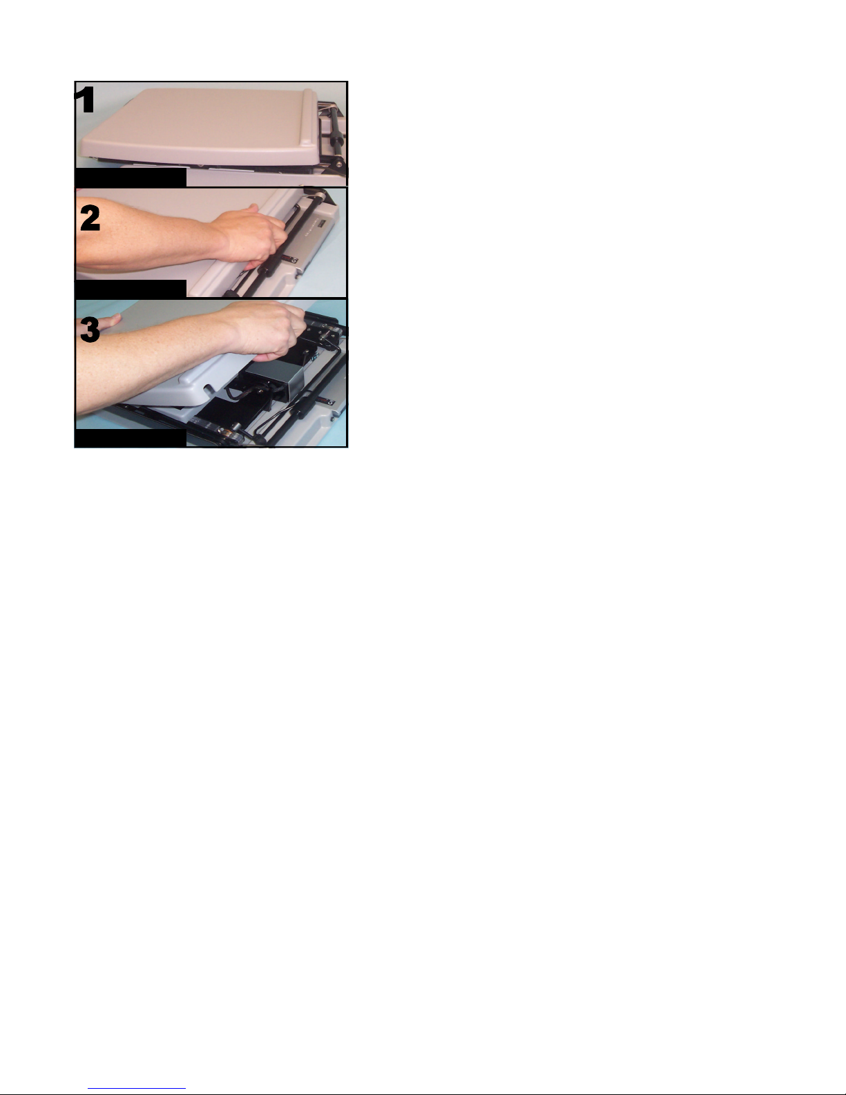
Opening the ViewTM.
1. Set the View on a flat surface. 2. Grasp the
back of the table top with the paper stop
raised edge and pull up and out. The table
top is held in place with 2 locking clips shown
below. 3. Lift up the tray.
Side View with monitor & camera up
7
View Folded Flat
Unclip the table
Lift up
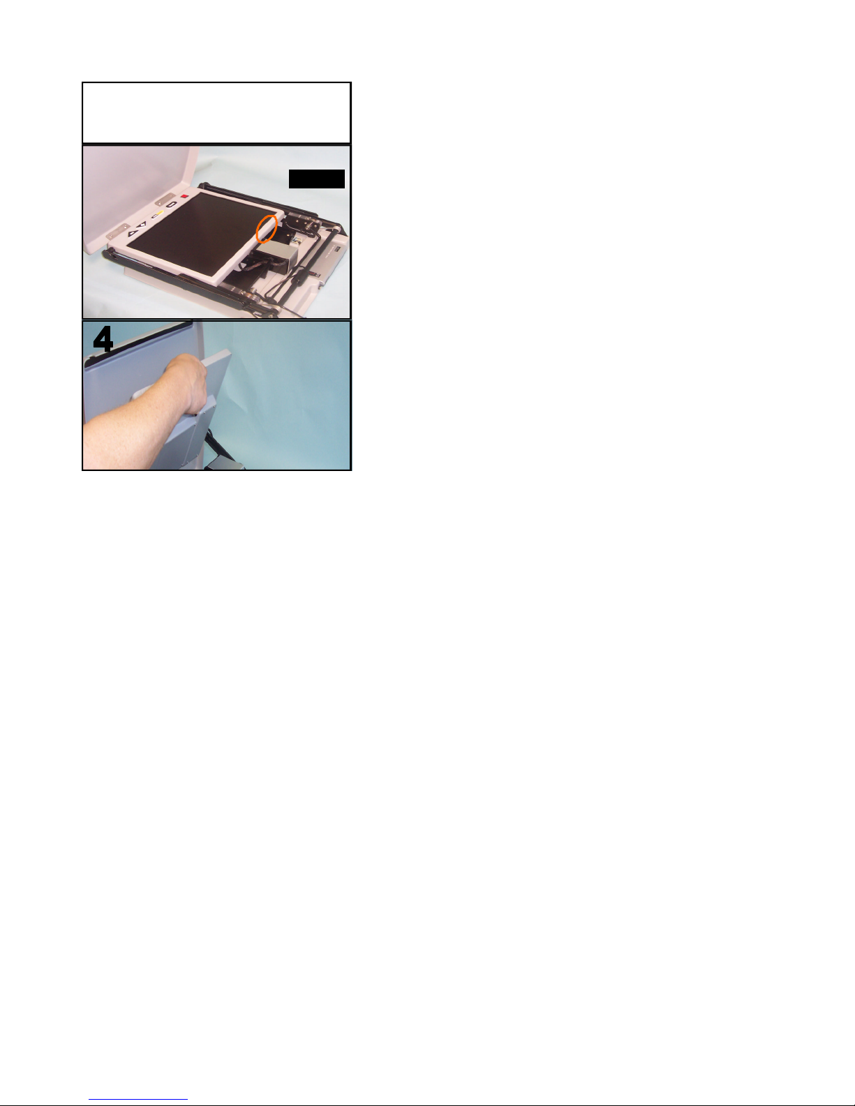
8
Lift here
Raise the table top to its fullest upright
position as shown below. 4. Grasp the top of
the monitor and lift up as shown below.

9
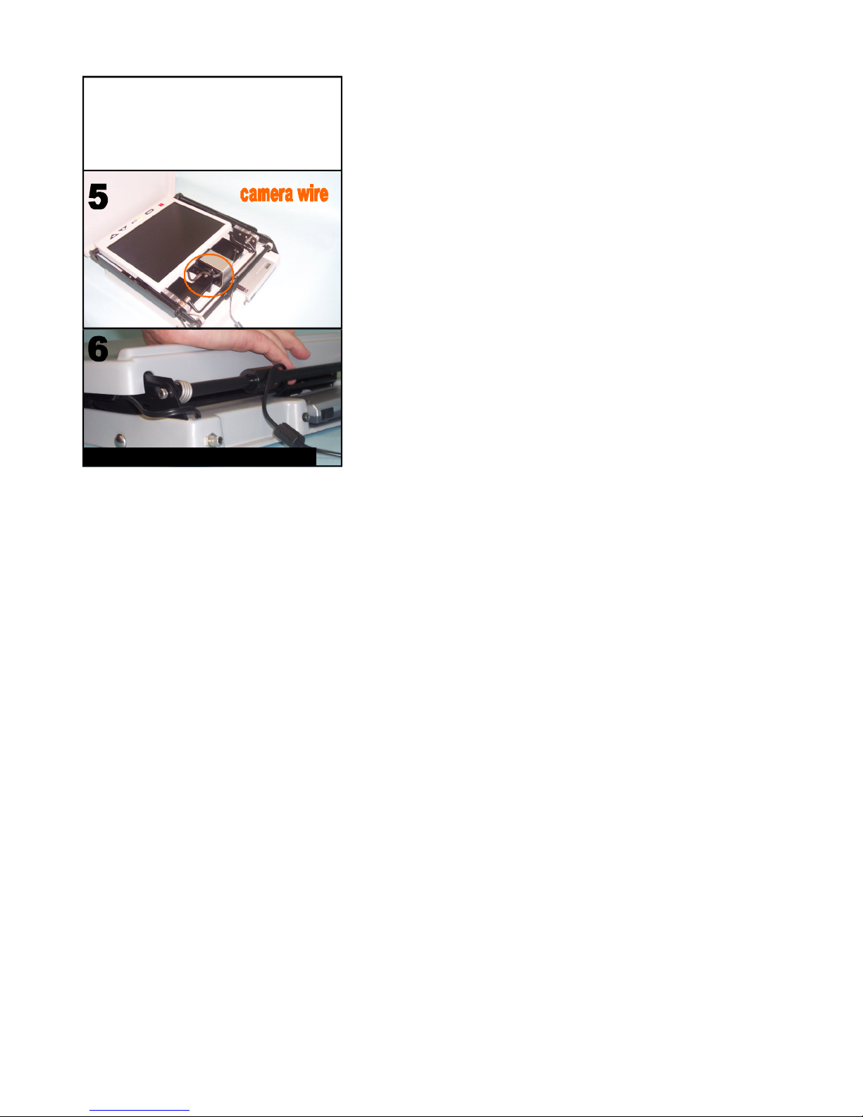
5. Reach in with one hand and pull the cam-
era up 2-3 inches to release the components.
6. Raise the monitor & camera will rise.
Raising the monitor also raises the camera
Lift up camera
10
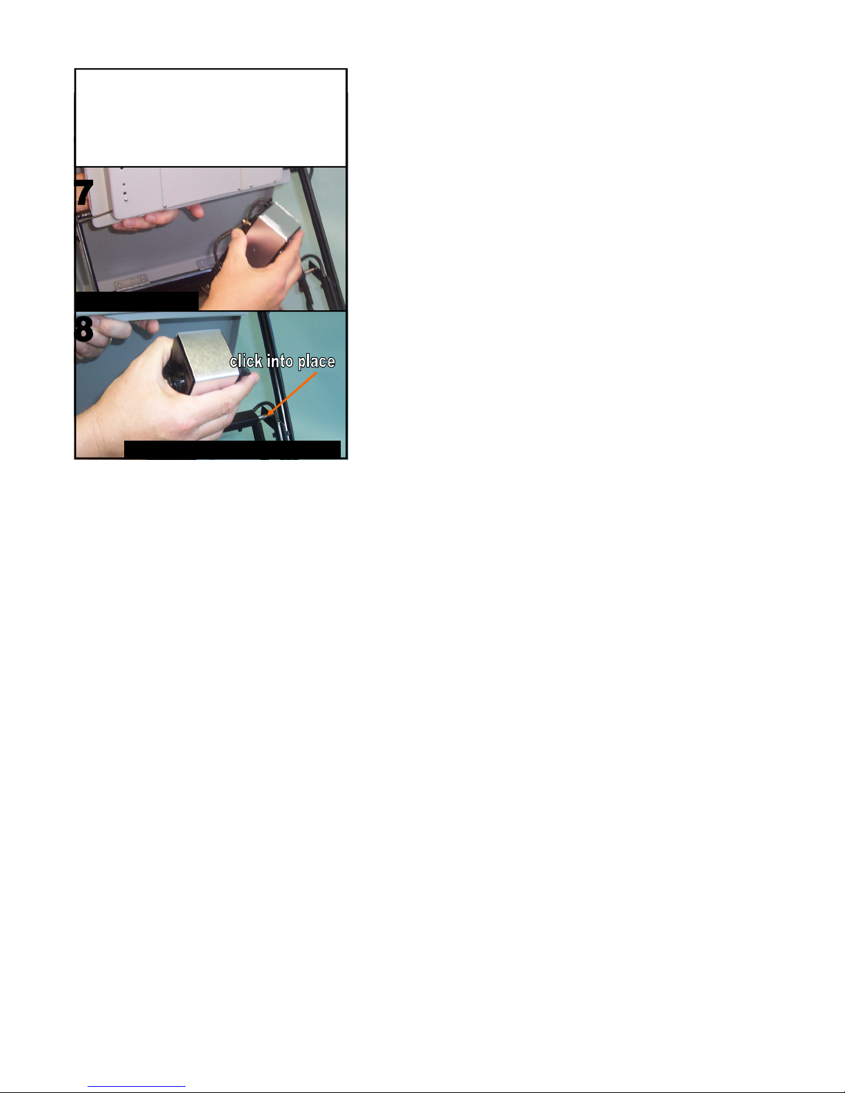
7. Support the monitor up with one hand and
turn the camera 180 degrees clockwise so the
U-bar is angled away from the monitor. 8.
Push up on the camera moving it towards the
monitor with a gentle motion until the camera
clicks into place.
Lift up camera U-bar to lock in place
Turn 180 degrees

11
9. Slide the tabletop out away from the
base until there is room to fold it down. 10.
Click into place by pressing down onto the
clips.
Lock onto clips
Slide tray out

12
Turn camera 180 degrees back to x-y table
viewing position, flip up for distance views
Adjust monitor to desired height

13
Closing the ViewTM.
Turn off power and unplug. Lift and support
the monitor in its highest position. 2. Slide
the tabletop out away from the base. Unclip
the top by pulling out on the back of the ta-
ble. 3. Lift table top and slide the black portion
back into the base.
Clips are
under
here.
Tip:
Press clips
in with
fingers for
quick
release
Slide in
14
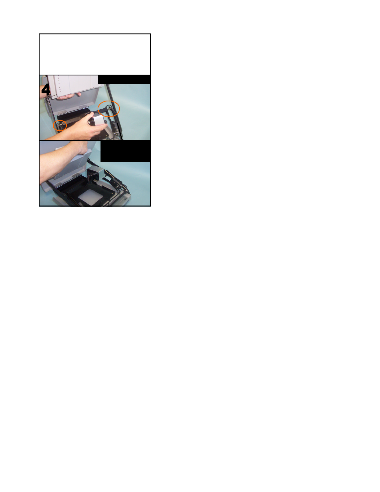
4. With the camera in the x-y viewing posi-
tion support the monitor and pull back on
the u-bar & camera to release it from the
locked position. Slowly let it collapse into
position. The camera will lower first.
Hold top of monitor
& keep black tray
pushed in
Unlock camera bar
15
5. Make sure the wires are tucked in be-
tween the two table clips. Fold down the
monitor and table top. 6. Press firmly on the
back of the table top to lock the table into
position. Place in carry case for safety.
Press down onto clips to lock in place

16
Operating Controls/Features
On\Off: The Red ON\OFF
switch is located on the left
portion of the front control
panel. To turn on monitor, press the
on\off button on the front of the
monitor.
Select Mode:(Button to the
right of the power button)
1. Full Color–is excellent for view-
ing photos
2. Black on White–makes any print
high contrast black and any back-
ground high contrast white.
3. White on Black–reverses the
back-ground (white print/
black background)
Brightness Control:(Center)
Press the left side of button to make
lighter. Press the right side of
button to make darker.
Zoom Larger: (2nd button
from the Right) to increase
magnification.
Zoom Smaller: (Right Button)
to decrease magnification

17
Operating Controls/Features
NTSC “Video Out” Port (located on the
left rear side of the base)
Connect a standard “NTSC”
RCA cable to this port & video
receiver (ie: LCD projector or
TV screen)
Quiet Mode
An audible tone is sounded when you press a
control button. To Change to Quiet Mode:
with the system turned off, hold down the
Mode button while turning the base unit on.
Release after you hear two beeps. To turn
the tone on again, repeat these same steps.
Auto-Focus
The VIEW is shipped in “continuous” Auto-
Focus mode. This means that the camera
brings the image into focus instantly. To
turn Auto-Focus off: press and hold the
Brightness control while powering system on.
Follow the same steps to turn Auto–Focus on
again.

18
Operating your View
The monitor on “The VIEWTM” raises and
lowers from table height up to 14 1/2” when
locked into place.
Distant Viewing
The camera on “The VIEWTM” is movable. To
change camera view, grasp camera and
rotate it to view desired object.
Mirror Image Viewing
Press the Contrast button to make image a
true mirror image.
X-Y Table
Place your reading material or other objects
on the X-Y table & move the table from side
to side or front to back to view the magnified
form on the display.
Helpful Tips
-Many users prefer reading in the white on
black mode (third mode) because there is
less glare.
-A black felt tip pen is the easiest to see and
using the black on white mode (second
mode) will give you the best image. Using
ruled paper with dark lines can also be very
helpful.

19
Care & Maintenance
The unit and display can be gently wiped
with a clean soft cotton cloth to remove dust
or dirt. Do not use any abrasive cleaners or
spray it with cleaning solution.
Do not store the VTI Video Magnifier at
temperatures below 14 degrees F or above
122 degrees F.
Make sure lid is snapped in place before
lifting machine by the handle. You may also
want to purchase a protective carrying case
(part# VSC available from your Distributor).
Warranty & Service
2 year limited warranty from date of
purchase.
If you are having problems with your VTI
Video Magnifier, please call 1-800-560-
7226 and ask for Technical Support. Do not
attempt to open the machine parts. Doing so
will void the warranty. When returning for
service ship insured for purchased price to:
Attn RA# (CALL 1-800-560-7226 TO OBTAIN)
Vision Technology, Inc.
8501 Delport Drive
St. Louis, Mo 63114

20
Vision Technology Inc.
Client Care
Technical Support
is available at
1-800-560-7226
M-F 8:00 -4:30 (CST)
This manual suits for next models
1
Table of contents
Other Vision Technology Magnifier manuals


