© 2017
www.classicexhibits.com
Order #XXXXX
Step 3 of 6
Backwall Assembly (cont’d)
1
5
E
F
3
3A
5A
6
7
4
2
BACK VIEW
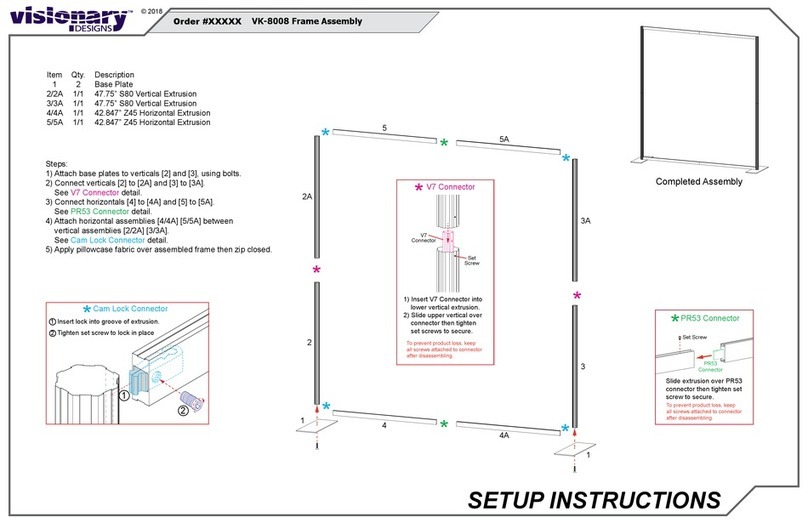
Item
1
2
2A
3
3A
4
5
5A
6
7
Qty.
1
1
1
1
1
1
1
1
1
1
Description
97.292”h S40 Vertical Extrusion w/ Mitered End (attached to Wall Panel E)
95.5”h S40 Vertical Extrusion w/ Hinge
95.5”h S10 Modul Connector (attached to Wall Panel F)
27.25”w Z45 Horizontal Extrusion
25.9572”w Z45 Curved Horizontal Extrusion
92.3716”w Z45 Curved Horizontal Extrusion
10.7262”w Z45 Horizontal Extrusion
25.9572”w Z45 Curved Horizontal Extrusion
92.3716”w Z45 Curved Horizontal Extrusion
95.5”h Z45 Vertical Extrusion
Steps:
1) Connect Horizontals [3], [3A], & [4] together. See Connector Bar
detail. Repeat step for Horizontals [5], [5A], & [6].
2) Connect Vertical [2] to Vertical [2A]. See Hinge Attachment detail.
3) Attach Horizontal assemblies between Verticals [1] & [2/2A].
4) Connect Vertical [7] to the back of Horizontals [4] & [6].
See Vertical Stabilizer detail.
*
*
*
*
Hinge Attachment
*
1) Insert Hinge into grooves of
Vertical Extrusions.
2) Fold Hinge to ‘closed’ position.
3) Tighten set screws to secure.
1
23
2A
Vertical Stabilizer
Screw Cap
Insert Screw Cap thru hole of Vertical
[7], then into threaded hole of
Horizontal. Turn Screw Cap to secure
Extrusions together.
Horizontal
Extrusion
Vertical
Extrusion
[7]
*
*
*
Connector
Bar
Set
Screw
Vertical
Extrusion
Connector Bar
*
Slide Vertical Extrusion over
fixed Connector Bar then
tighten Set Screw secure.
*
*

