REED ST-9800T User manual

reedinstruments
www com
Model ST-9800T
True RMS
AC/DC Clamp Meter
with Temperature
Function
Instruction
Manual

reedinstruments
www com
2
Table of Contents
Safety ............................................................................................ 2
Meter Description.......................................................................... 4
Specications.............................................................................5-6
Operating Instructions................................................................7-9
Battery Replacement..................................................................... 9
For service on this or any other REED product, contact REED Instruments
at info@reedinstruments.com.
Safety
International Safety Symbols
This symbol, adjacent to another symbol or terminal, indicates
the user must refer to the manual for further information.
This symbol, adjacent to a terminal, indicates that,
under normal use, hazardous voltages may be present
Double insulation
Safety Notes
• Do not exceed the maximum allowable input range of any function
• Do not apply voltage to meter when resistance function is selected.
• Set the function switch OFF when the meter is not in use.

reedinstruments
www com
3
Warnings
• Set function switch to the appropriate position before measuring.
• When measuring volts do not switch to current/resistance modes.
• When changing ranges using the selector switch always disconnect the
test leads from the circuit under test.
• Do not exceed the maximum rated input limits.
Cautions
• Improper use of this meter can cause damage, shock, injury or death.
Read and understand this user manual before operating the meter.
• Always remove the test leads before replacing the battery.
• Inspect the condition of the test leads and the meter itself for any damage
before operating the meter. Repair or replace any damage before use.
• Use great care when making measurements if the voltages are greater than
25VAC rms or 35VDC. These voltages are considered a shock hazard.
• Remove the battery if the meter is to be stored for long periods.
• Always discharge capacitors and remove power from the device under
test before performing Diode, Resistance or Continuity tests.
• Voltagechecksonelectricaloutletscanbedifcultandmisleading
because of the uncertainty of connection to the recessed electrical
contacts. Other means should be used to ensure that the terminals are
not “live”.
• Iftheequipmentisusedinamannernotspeciedbythemanufacturer,
the protection provided by the equipment may be impaired.
Input Limits
Function Maximum Input
A AC, A DC 600A
V DC, V AC 600V DC/AC
Resistance, Capacitance, Diode Test 250V DC/AC
Temperature 60V DC, 24V AC

reedinstruments
www com
4
Meter Description
1. Current clamp
2. Data Hold button
3. Peak Hold button
4. Mode select button
5. ZERO button
6. LCD display
7. COM input jack
8. Clamp trigger
9. Rotary Function switch
10. V/ΩCAP/TEMPjack
Display Description
1. AC (alternating current) & DC (direct currrent)
2. Minus sign
3. 4000 count (0 to 3999) measurement reading
4. AutoRange mode
5. Peak Hold mode
6. Diode test mode
7. Audible Continuity
8. Data Hold mode
9. ZERO (Relative) mode
10. Low Battery icon
11. Units of measure list

reedinstruments
www com
5
Specifications
Function Range & Resolution Accuracy (% of reading)
DC Current 400.0 ADC 0 to 70A: ± (2.5% + 0.6A)
70 to 300A: ± (3.0% + 0.3A)
300 to 400A: ± (3.5% + 0.3A)
600 ADC 0 to 150A: ± (2.5% + 4A)
151 to 350A: ± (3.0% + 4A)
351 to 600A: ± (4.0% + 6A)
AC Current 400.0 AAC 0 to 70A: ± (3.0% + 0.6A)
70 to 300A: ± (3.5% + 0.3A)
300 to 400A: ± (3.5% + 0.6A)
600 AAC 0 to 150A: ± (3.0% + 4A)
151 to 350A: ± (3.5% + 5A)
351 to 600A: ± (4.0% + 8A)
DC Voltage 400.0 mVDC ± (0.5% + 5 digits)
4.000 VDC
± (1.2% + 3 digits)40.00 VDC
400.0 VDC
600 VDC ± (1.5% + 3 digits)
AC Voltage 4.000 VAC ± (1.0% + 5 digits)
40.00 VAC ± (1.5% + 3 digits)
400.0 VAC
600 VAC ± (2.0% + 4 digits)
Resistance 400.0Ω ± (1.0% + 4 digits)
4.000KΩ
± (1.5% + 2 digits)40.00KΩ
400.0KΩ
4.000MΩ ± (2.0% + 3 digits)
40.00MΩ ± (3.0% + 5 digits)
Temperature -4 to 1400°F ± (3.0% + 5°)
-20 to 760°C

reedinstruments
www com
6
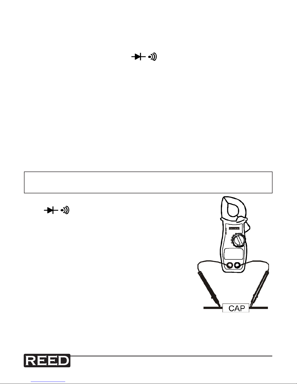
Capacitance 40.00 nF ± (5.0% + 7 digits)
400.0 nF
± (3.5% + 5 digits)4.000 uF
40.00 uF
100.0 uF ± (5.0% + 5 digits)
Clamp size Opening 1.3” (33mm) approx
Diode Test Test current of 0.3mA typical;
Open circuit voltage 1.5V DC typical.
Continuity Check Threshold<50Ω;Testcurrent<1mA
Low Battery Indication “BAT” is displayed
Overrange Indication “OL “ is displayed
Measurements Rate 2 per second, nominal
Temperature sensor Type K thermocouple
Input Impedance 7.8MΩ(VDCandVAC)
Display 3-3/4 digits (4000 counts) LCD
AC bandwidth 50/60Hz (AAC and VAC)
AC response True rms (AAC and VAC)
Operating Temperature 14 to 122°F (-10 to 50°C)
Storage Temperature -14 to 140°F (-30 to 60°C)
Relative Humidity 90%(0°C to 30°C); 75%(30°C to 40°C);
45%(40°C to 50°C)
Altitude Operating: 3000m; Storage 10,000m
Over voltage Category II 600V
Battery 9V Battery
Auto OFF approx. 15 minutes
Dimensions/Weight 8x3.2x1.7” (204x80x43mm)/0.62 lbs. (281g)
Safety For indoor use and in accordance with
Overvoltage Category II, Pollution Degree 2.
Category II includes local level, appliance,
portable equipment, etc., with transient
overvoltages less than Overvoltage Cat. III

reedinstruments
www com
7
Operating Instructions
NOTE: Read and understand all warning and precaution statements
listed in the safety section of this operation manual prior to using this
meter. Set the function select switch to the OFF position when the
meter is not in use.
AC/DC Current Measurements
WARNING: Ensure that the test leads are disconnected from the meter
before making current clamp measurements.
1. Set the Function switch to the
600 or 400A range. If the range of the
measured is not known, select the
higherrangerstthenmovetothe
lower range if necessary.
2. Select AC or DC with the AC/DC
button. Press the zero button to zero
the meter in the DCA mode only.
3. Press the trigger to open jaw. Fully en-
close one conductor to be measured.
4. The clamp meter LCD will display the
reading.
AC/DC Voltage Measurements
1. Insert the black test lead into the
negative COM terminal and the red test lead
into the positive Vterminal.
2. Set the function switch to the Vposition.
3. Select AC or DC with the AC/DC button.
4. Connect the test leads in parallel
to the circuit under test.
5. Read the voltage measurement
on the LCD display.

reedinstruments
www com
8
Resistance and Continuity Measurements
1. Insert the black test lead into the negative COM terminal and the red
test lead into the positive terminal.
2. Set the function switch to the ΩCAP position.
3. Use the multifunction button to select resistance.
4. Touch the test probe tips across the circuit or component under test. It
is best to disconnect one side of the device under test so the rest of the
circuit will not interfere with the resistance reading.
5. For Resistance tests, read the resistance on the LCD display.
6.ForContinuitytests,iftheresistanceis<50Ω,atonewillsound.
Capacitance Measurements
WARNING: To avoid electric shock, discharge the capacitor under test
before measuring.
1. Set the function switch to
the ΩCAP Position.
2. Press the multifunction button to select the
capacitance function.
3. Insert the black test lead banana plug into
the negative (COM) jack and the red test
lead banana plug into the positive jack.
4. Touch the test probe tips across the part
under test.
5. Read the capacitance in the display.
6. The display will indicate the proper decimal
point and value.

reedinstruments
www com
9
Temperature Measurements
WARNING: To avoid electric shock, disconnect both test probes from
any source of voltage before making a temperature measurement.
1. Set the function switch to TEMP.
2. Insert the Temperature Probe into the negative (COM) and the positive
jacks, making sure to observe the correct polarity.
3. Touch the Temperature Probe head to the part whose temperature you
wish to measure. Keep the probe touching the part under test until the
reading stabilizes (about 30 seconds).
4. Read the temperature in the display. The digital reading will indicate the
proper decimal point and value.
WARNING: To avoid electric shock, be sure the thermocouple has been
removed before changing to another measurement function
Data Hold
To freeze the LCD meter reading, press the data hold button. The data
hold button is located on the left side of the meter (top button). While data
hold is active, the DH display icon appears on the LCD. Press the data
hold button again to return to normal operation.
Peak Hold
To hold the highest reading on the LCD, press the peak hold button. The
peak hold button is located on the left side of the meter (bottom button).
The meter reading will not change as readings change, rather it will only
display the highest reading encountered since the peak hold button was
pressed. Press the peak hold button again to return to normal operation.
Battery Replacement
1. Remove the three rear Phillips head screws
2. Open the battery compartment
3. Replace the ‘9V’ battery IEC 6F22, NEDA 1604.
4. Re-assemble the meter

reedinstruments
www com
10
Notes _________________________________________
________________________________________________
________________________________________________
________________________________________________
________________________________________________
________________________________________________
________________________________________________
________________________________________________
________________________________________________
________________________________________________
________________________________________________
________________________________________________
________________________________________________
________________________________________________
________________________________________________
________________________________________________
________________________________________________
________________________________________________
Table of contents
Other REED Measuring Instrument manuals
Popular Measuring Instrument manuals by other brands

Lauper Instruments
Lauper Instruments Easidew Online user manual

Luxinar
Luxinar SR AOM Series user manual

Tecnosystemi
Tecnosystemi Toolsplit TSC200001 user manual

SP tools
SP tools SP61005 user manual

Onset
Onset T-VER-AH02 installation guide

National Geographic
National Geographic 90-33000 operating instructions

Optec
Optec UMG-604-PRO User manual and technical data

GE
GE Moisture Image 1 Series Programming manual

Blue-White industries
Blue-White industries F-1000 instruction manual

DINKO Instruments
DINKO Instruments D-13CEM instruction manual

TECALEMIT
TECALEMIT TecSonic 225800200 operating manual

Pitney Bowes
Pitney Bowes DM200 quick guide