vita V60 i-Line User manual

VITA V60 i-Line®
VITA shade, VITA made.
Date of issue 02.15
Operating manual
VITA Farbkommunikation
VITA shade control
VITA shade reproduction
VITA shade communicationVITA shade determination


3
VITA V60 i-Line
®
1 Table of contents
2 Foreword 4
2.1 Dear Customer 4
3 Scope of delivery 5
3.1 Device supplied in a special box with: 5
3.2 Accessories (can be purchased separately): 5
4 Technical information 5
4.1 General description 5
5 Technical data 5
5.1 Dimensions / weights 5
6 Electrical specifications 6
6.1 Furnace 6
6.2 VITA vacuum pump 6
7 Intended use 6
7.1 Basis for the construction of the device 6
7.2 Prohibited modes of operation 6
7.3 Permitted modes of operation 6
8 Safety information 7
8.1 Symbols 7
8.2 Ambient conditions 7
8.3 Safety features 7
9 Installation and connections 8
9.1 Installation location 8
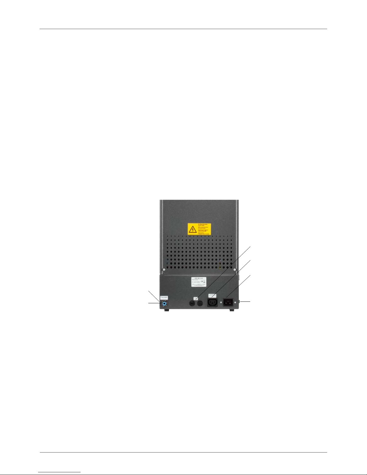
9.2 Device connections 8
10 Startup 9
10.1 Switching off the device, ending operation 9
11 Cleaning the furnace 10
11.1 Cleaning the touchscreen 10
11.2 Cleaning firing for the firing chamber 10
11.3 Firing chamber insulation 10
12 CE marking 11
13 Mains power supply failure 11
14 Warranty and liability 12
14.1 Spare parts 12
15 Touchscreen operation 12
16 Switching on the device 13
16.1 Starting / switching to standby 13
17 Operation and functions 14
18 Keypad functions 15
19 Starting / selecting firing programs 16
20 Modifying program values 17
20.1 Pre-drying 18
20.2 Increase in temperature and temperature hold time 19
20.3 Cooling 20
20.4 Vacuum setting 21
20.5 Saving program values 22
20.6 Fast cooling 22
20.7 Program lock 23
20.8 Program names –
creating / modifying material names 24
21 Device settings 25
21.1 Device information 26
21.2 Factory defaults 26
21.3 Temperature setting 27
21.4 Temperature display °C or °F 28
21.5 Language 28
21.6 PIN-input for device settings 28
21.7 PIN-input for firing programs 29
21.8 Locking firing programs 29
21.9 Tone duration for the speaker 30
21.10 Display settings 31
21.11 Setting the standby temperature 31
22 Recording process data/ firing data system 32
22.1 Exporting / importing programs 32
23 Software update 33
24 Error messages 34
25 Alphabetical index 35

4
VITA V60 i-Line
®
2 Foreword
2.1 Dear Customer,
Congratulations on your decision to purchase VITA V60 i-Line, a modern furnace system for dental use. As a quality manufacturer
of ceramic dental materials and devices, VITA Zahnfabrik can assure you that only materials of superior quality have been used in
the development and manufacture of VITA V60 i-Line. Thirty years of experience in developing ceramic furnaces are reflected in this
product, which will make it a pleasure to work with for many years to come.
This device has been designed in accordance with the latest technological benchmarks and complies with all international safety
standards. Nevertheless, incorrect use can be dangerous – please read this operating manual and bear in mind the information
provided.
Reading and understanding this operating manual will help you maintain safety, reduce expenses as a result of repairs and downtime,
and increase the reliability and service life of the device. All of the illustrations and drawings in this operating manual are intended for
general explanatory purposes and are not authoritative for the detailed construction of the device.
The operating manual must always be kept close to the device. It must be read and followed by all persons responsible for performing
tasks such as operation, troubleshooting during operation, and cleaning and servicing (maintenance, inspection, repairs), either with or
on the device.
We hope that you will find using VITA V60 i-Line to be an enjoyable and successful experience.
Copyright
This operating manual must be treated as confidential. It should only be used by persons with the corresponding authorization.
Disclosure to third parties is only permitted with the written consent of VITA Zahnfabrik H. Rauter GmbH & Co. KG.
All documents are protected in accordance with copyright law. The distribution and reproduction of documents, in whole or in part,
and the use or communication of their content are prohibited without express authorization.
Violations are punishable by law and necessitate compensation.
All rights to exercise industrial property rights are reserved.
Note:
Information:
This note warns of dangerous situations that may result in personal injury or damage
to the device.
This note highlights useful advice, explanations and supplementary information.

5
VITA V60 i-Line
®
3 Scope of delivery
3.1 Device supplied in a special box with:
• 1 furnace: VITA V60 i-Line
• 1 firing socket
• 1 power supply cable
• 1 operating manual
• 1 connection cable for the vacuum pump
• 1 vacuum tube
• 2 firing object storage trays at the side
3.2 Accessories (can be purchased separately):
• Vacuum pump: 230 / 240 V, 50 / 60 Hz, 115 V, 50 / 60 Hz
or 100 V, 50 / 60 Hz.
• FDS (firing data system)
firing data administration program for PC use
• 2 firing object storage trays at the side
4 Technical information
4.1 General description
• Maximum temperature accuracy (plus/ minus 2 °C)
for optimum firing results
• Convenient operation that saves you time, modest space requirements
• 2 firing object storage trays at the side
• Firing chamber fitted with high quality insulation material
• Quartz firing muffle
• Temperature sensor (platinum / rhodium-platinum)
• Automatic temperature calibration
5 Technical data
5.1 Dimensions / weights
• Width: 260 mm
• Depth: 420 mm
• Height: 570 mm
• Weight: 18 kg
• Effective dimensions of the firing chamber:
diameter: 90 mm, height: 55 mm
• Firing chamber temperature: max. 1200 °C

6
VITA V60 i-Line
®
6 Electrical specifications
6.1 Furnace
• Electrical connection: 230 VAC, 50 Hz
or 100 / 110 VAC, 50 / 60 Hz
• Power consumption: max. 1500 W
6.2 VITA vacuum pump
• Electrical connection: 230 V, 50 / 60 Hz
or 100 / 110 V, 50 / 60 Hz
• Power consumption: max. 200 W
• End vacuum: < 960 mbar
• Dimensions: 320 x 110 x 220 mm
• Weight: approx. 6.4 kg
7 Intended use
7.1 Basis for the construction of the device
The device has been engineered in accordance with the latest technological
benchmarks and established safety regulations. Nevertheless, incorrect use
can endanger the health and safety of the user or third parties, and result in
damage to the device and other property.
7.2 Prohibited modes of operation
The operation of the device using power sources, products, etc. that are
subject to legislation governing hazardous substances or that affect the
health of the operating personnel in any way is prohibited, as is the use of
equipment modified by the operator.
7.3 Permitted modes of operation
The operation of the device is only permitted if this operating manual has
been read and understood thoroughly and the procedures described in it
have been observed. Any other use or use beyond what is specified, e.g. the
processing of products other than those intended as well as the handling
of hazardous materials or substances harmful to health does not constitute
intended use. The manufacturer / supplier is not liable for any damage
resulting from such use. The risk is borne exclusively by the user.

7
VITA V60 i-Line
®
8 Safety information
8.1 Symbols
Hazardous voltage
Separate disposal
Hot surface
This symbol warns of hazardous voltage.
Before opening the device, it must be disconnected from the mains power supply by pulling out
the mains plug.
Ensure that electrical/electronic devices are disposed of separately, and not together with
household waste.
The black bar under the bin symbol means that the device was sold after 13.08.2005. Please
note that the device is subject to directive 2002/96/EC (WEEE) and the applicable national law in
your country, and must be disposed of accordingly. Contact your dealer when device disposal is
required.
This symbol warns of hot surfaces.
Risk of burns.
The manufacturer is not liable for accidents involving the user when
the device is open!
Never start up devices without the firing socket attached. In continuous
operation (max. end temperature, max. firing time), parts of the firing chamber
may reach increased temperatures (above 70 °C).
Do not reach into the open firing chamber when the device is connected.
There is a risk when touching electrically live or hot parts of burns or of
electric shock.
8.2 Ambient conditions
• Indoor use
• Ambient temperature: -10 °C to 40 °C
• Relative humidity: 80% at 40 °C
• Max. altitude 3800 m
• Rated voltage fluctuations must not exceed plus 10%
and minus 15% of the rated voltage.
8.3 Safety features
The furnace is fitted with the following safety and monitoring features:
• Temperature sensor monitoring
• Temperature monitoring
• Vacuum monitoring
• Power failure protection

8
VITA V60 i-Line
®
9 Installation and connections
9.1 Installation location
• Install the device in a dry, heated room so that the distance to the
closest wall is at least 25 cm (see section 8.2 Ambient conditions).
• When the temperature is below 15 °C (e.g. after transport), leave the
device to stand for approx. 30 minutes at room temperature before
startup.
• Ensure that the device is installed on a heat-resistant surface.
The radiation and heat development of the device is within a non-
hazardous range. However, it cannot be completely ruled out that
furniture surfaces and veneers sensitive to heat may show slight
discoloration over time due to the continuous exposure to heat.
• Avoid exposing the device to direct sunlight.
• Do not place any flammable objects near the device.
• Do not install the device in such a way that it becomes difficult to press
the main switch and pull out the power supply cable.
9.2 Device connections
USB port at the side
Connection for vacuum tube
2 device fuses*
Connection for vacuum pump
Connection for mains power supply
Main switch at the side
* The identification plates provide information about the fuses used in the device.
Fuses with other ratings may not be used.
230 V model: T 8 H 250 V
100 / 110 V model: T 15 H 250 V

9
VITA V60 i-Line
®
10 Startup
Before startup, note the safety information in section 1.10!
For information about the connections provided by the device, see section 9.2
• Connect the vacuum pump to the device with the electrical connection
and tube connection.
• Connect the device to the mains power supply using the power supply
cable provided.
Important: Avoid electrical connections with multiple socket
outlets using extension leads, as there is a risk of fire in the event
of an overload.
• Switch on the device using the main switch. The lift moves to the lower
position.
• Clean or wipe the lift plate and the lift plate gasket (dust particles from
the insulation during transportation of the device).
• Attach the firing socket to the lift plate.
Important: Never start up the device without the firing socket
attached.
10.1 Switching off the device, ending operation
When the device is not in operation, retract the lift into the firing chamber
and switch off the device using the main switch. Closing the firing chamber
protects the insulation and prevents the absorption of moisture.

10
VITA V60 i-Line
®
11 Cleaning the furnace
Important: Always pull out the mains plug before cleaning!
It is not necessary to clean the inside of the firing chamber.
Cleaning the casing at regular intervals with a damp cloth contributes to
operational reliability.
Important: Never use detergents or flammable liquids during
cleaning.
11.1 Cleaning the touchscreen
Dirt on the display as a result of dust or fingerprints can be removed using a
microfiber cloth. Cleaning should be carried out with the device switched off in
order to prevent functions from being adjusted inadvertently on the display.
11.2 Cleaning firing for the firing chamber
The firing chamber only requires cleaning firing in the event of non-compliance
with the permitted modes of operation (see section 7.3).
If cleaning firing nevertheless becomes necessary, this can be performed using
the standby program (see section 16.1)
To do so, set the standby temperature to 800 °C using the device settings/
standby temperature (see section 21.11).
Start the standby program and move the closed lift downwards by approx. 5 cm
to allow the particles of dirt to evaporate. Cleaning firing should be performed
for approx. 20 minutes.
11.3 Firing chamber insulation
The firing chamber contains insulating material comprised of ceramic mineral
fibers (index no. 650-017-00-08) that have been classified as category 2
carcinogens (Annex VI, EC 1272/2008). When working with the firing chamber
or replacing the firing muffle, fiber dust may be discharged. Exposure to this
dust can potentially be carcinogenic on inhalation, as well as result in irritation
of the skin, eyes and respiratory organs.
When replacing the firing muffle, proceed as follows:
• Long-sleeved protective clothing
• Wear safety goggles as well as protective gloves
• Use a dust vacuum system or wear a FFP 2 respirator
Once work has been completed, rinse dust from unprotected skin using cold
water. Wash the workwear used separately from everyday clothing.

11
VITA V60 i-Line
®
12 CE marking
With the CE mark, a legally binding declaration is made to the effect that the
device corresponds to the fundamental requirements of directive 2006/95/EC
(Low Voltage Directive) and directive 2004/108/EC/EWG (EMC Directive).
13 Mains power supply failure
The device is equipped with power failure protection. This component
prevents program interruption and therefore any misfiring in the event of a
brief failure of the mains power supply. The power failure protection becomes
effective as soon as the mains power supply fails when a firing program is
running.
Failure of the mains power supply for less than approx. 1 minute
30 seconds:
The program continues to run when the mains power supply returns and is
not interrupted. The display does not operate during this time. The display
shows the current program again when the mains power supply returns.
Failure of the mains power supply for more than approx.1 minute
30 seconds:
The program is interrupted. The display is no longer in operation. When the
mains power supply returns, a signal tone is emitted for 3 seconds and the
display indicates that firing cannot be continued.
When the mains power supply returns, restart takes approx. 1 minute
30 seconds.

12
VITA V60 i-Line
®
14 Warranty and liability
Warranty and liability are regulated in accordance with the terms and
conditions of the contract. In the event of software modifications without the
knowledge and approval of VITA Zahnfabrik H. Rauter GmbH & Co. KG, all
liability and warranty entitlements are invalidated.
14.1 Spare parts
Spare parts must comply with the technical requirements stipulated by the
manufacturer. This is always assured when using original VITA spare parts.
Further information on this device is available on our homepage:
http://www.vita-zahnfabrik.com
Software updates are available to download under Products / Ovens /
Furnaces /New furnaces.
An option to register is also provided under Newsroom / Update
Messenger so that the latest information on the device is automatically
emailed to you by the Update Messenger. In case of technical queries
regarding the device or regarding repair services and warranty provisions,
contact us at:
E-Mail: instruments-service@vita-zahnfabrik.com
Tel. +49 (0) 7761 / 562 -105, -106, -101
15 Touchscreen operation
The touchscreen is operated using the touch-sensitive surface of the screen.
In order to activate a function, press the corresponding button with your
finger. Pressing a button lightly with your finger will first cause the button to
change color (the button goes dark). Lifting your finger from the button then
activates the selected function.
Buttons should only be pressed lightly with your finger. The
function is activated when you lift your finger. Applying too much
pressure, or pressing using sharp or hot objects will damage the
touchscreen.

13
VITA V60 i-Line
®
16.1 Starting / switching to standby
Press the standby button. The lift is retracted into the firing chamber and the
firing chamber heated to the standby temperature as set. Once the standby
temperature has been reached and maintained for 5 minutes, the device is
ready for firing. When standby is started for the first time after the furnace is
switched on, the firing chamber remains slightly open for 5 minutes in order
to remove moisture from the firing chamber.
The standby button shows two temperature values. You can choose between
normal mode (standby temperature can be set to, e.g., 500 °C) and power-
save mode (fixed value of 200 °C). The temperature during normal mode can
be adjusted using the device settings / standby temperature. (See section
21.11.) Pressing the button again while standby is active allows you to switch
between normal and power-save mode. The active mode is shown in red.
Standby is exited when the green START or red STOP button, the program
name button, or the program number button are pressed.
standby button
Last firing program selected
Start screen
16 Switching on the device
Switch on the device using the main switch (on the left of the device).
The red and green LEDs next to the display light up. If the firing chamber
temperature is less than 200 °C, the lift performs a reference run.
After approx. 30 seconds, the start screen is displayed on the control unit and
the red LED goes out. A self-test is carried out during this time.
After a further 60 seconds, the last firing program used is displayed.
1st dentine firing
1st dentine firing
STOP button
START button

14
VITA V60 i-Line
®
1 2 3 4
5
6
7
8
914 10 15 11 16 12 17 13
17 Operation and functions
Program overview
No.
1
2
3
4
5
6
7
8
9
10
11
12
13
14
15
16
17
Name
Program lock
Program number
Program name
Temperature display
Pre-drying
1st increase in temperature / hold time
2nd increase in temperature / hold time
Cooling
Lift positions
Standby
Device settings
Fast cooling
STOP button
Buttons for lift
Vacuum
Save button
START button
Function
Lock is open, program is freely accessible – Lock is closed, program is locked
Input field for program numbers 1 - 200
Input / modification of program names, program list
Shows the current temperature in the firing chamber
Pre-drying program area
Program area for 1st increase in temperature and 1st temperature hold time
Program area for 2nd increase in temperature and 2nd temperature hold time
Program area for cooling to a lower temperature with hold time
Shows the number of lift positions for pre-drying
Heats to standby temperature (normal and power-save mode)
Setting / display of the language, operating hours, etc.
Fast cooling of firing chamber temperature to standby temperature
Cancels the program
Manual lift control
Program area for vacuum settings
Saves changes
Starts the program
Reference
20.7
19
20.8
20.1
20.2
20.2
20.3
16.1
21
20.6
19
20.4
20
Program sections
1st dentine firing

15
VITA V60 i-Line
®
18 Keypad functions
Touching a program area in the program overview displays the corresponding
editing window with a keypad. The values set in the program sections can be
modified in the editing window.
Example: Vacuum editing
Button for deactivating / activating the function
Display fields for the program sections (see section 17)
Buttons 0-9 – program value input
Deletes the last digit entered in the display field
Deletes the value in the display field
Returns to the program overview without adopting the change
Returns to the program overview and adopts a change without saving
Selects the next input field
The time /temperature input fields can also be selected
directly from within each function.

16
VITA V60 i-Line
®
4. The selected program is displayed.
5. Start the program using the START button
7. The sequence of the program is shown in color
8. The program can be cancelled using the STOP button
19 Starting / selecting firing programs
In VITA V60 i-Line, firing programs are already pre-programmed for VITA
ceramic materials. These correspond to the settings recommended by VITA.
A firing program is selected by entering the number. The preset program
number assignment can be viewed via the program names (see section 20.8
on program name modification).
Pressing the program number or the material or program name briefly results
in selection of the program.
1. Press the program number button
2. Enter the program number (1-200)
3. Confirm the selected firing program
1st dentine firing
1st dentine
2nd dentine firing
2nd dentine firing

17
VITA V60 i-Line
®
20 Modifying program values
To modify program values, touch the relevant program area in which the
values are to be changed. The corresponding editing window opens and
modifications can be made to the program.
Program values shown in white are saved values. Program values shown in
red apply for a program sequence until a program change is implemented.
When the program is reselected, the previously-stored values are displayed
again.
The program values shown in red can be saved permanently using the
save button if a program lock (see section 20.7) has not been set (lock is
open). The program is then available for editing and the save button is shown
as active (see section 20.5).
If the program lock is active (lock is closed), changes can be made once.
However, it is only possible to save the changes by entering the PIN using the
keypad shown once the save button is pressed (see section 21.8).
Shows the current lift position
see section 20.1
Vacuum settings
see section 20.4
Save button
see section 20.5
Pre-drying
(see section
20.1)
1st increase in tem-
perature / hold time
(see section 20.2)
2nd increase in tem-
perature / hold time
(see section 20.2)
Cooling
(see section 20.3)
1st dentine firing

18
VITA V60 i-Line
®
20.1 Pre-drying
Press the pre-drying program area.
The display shows:
Selected program area, here:
pre-drying, is shown as active
The display field for the pre-drying time
lights up in light blue and is active. Enter
the value for the time using the keypad.
Input value: 0:00-40:00 min / sec.
Display field for the pre-drying temperature.
Enter the temperature using the keypad.
Input value: 200 °C - 800 °C.
Activates/ deactivates
pre-drying
In this mode, all program areas
can be selected and edited.
Time for the upper lift position
(calculated automatically)
Time setting for the middle lift position
Time settings for the lower lift position
Lift position settings
Icons indicate the lift positions
Times for the individual pre-drying positions:
The hold times possible for the individual lift positions depend on the pre-
drying time that has already been selected. For this reason, set the pre-drying
time first before entering the time for the middle and lower lift position. The
time for the upper lift position is calculated automatically.
If the pre-drying time is extended, the change in time is allocated to the
upper lift position. The lower and middle positions are retained.
If the pre-drying time is shortened, the hold time is shortened for the
upper lift position. The lower and middle positions are retained.
If the selected pre-drying time is less than the total time of the individual lift
hold times, this is allocated at 1/3 each to the individual lift positions.
The lift positions (in %) are retained if the hold times are changed and can be
modified as required. The factory defaults are set as follows: lift position 1 at
0%, lift position 2 at 15% and lift position 3 at 30%.
Program values that have been modified are shown in red in the program
overview and can be used for a program sequence or saved permanently
using the save button in the program overview (see section 20.5).
Changes to the pre-drying temperature result in changes to the
activation temperature of the vacuum pump. Changes to the pre-
drying temperature result in changes to the hold times of the lift
positions.

19
VITA V60 i-Line
®
20.2 Increase in temperature and temperature hold time
The device is fitted with two program sections for increases in temperature
and temperature hold time.
The 1st increase in temperature/hold time and 2nd increase in temperature /
hold time can each be activated or deactivated. Both sections are operated in
the same way.
Press the first or second program sections.
The display shows:
1st increase in temperature / hold time
shown as active
2nd increase in temperature / hold time
not active
Activate and/or deactivate
1st or 2nd increase in temperature / hold time
All program sections can be
selected and edited in this mode.
Setting for rise time
Setting for temperature hold time
Setting for heating rate
Setting for end temperature
Settings (values) for end temperature: Min. and max. values depend
on the activated program sections. If the end temperature is modified, the
heating rate in °C / min. is retained and the rise time in min/sec. adapted.
Important: The operating time of the vacuum pump is adapted to the
rise time.
Settings (values) for rise time: Min. and max. values depend on the
activated program sections.
If the rise time is modified, the heating rate in °C / min is adapted.
Important: The operating time of the vacuum pump is adapted to the
rise time. The pump is switched off once the end temperature has been
reached.
Settings (values) for heating rate: Min. and max. values depend on the
activated program sections. If the heating rate in °C/ min is modified, the rise
time is adapted.
Important: The operating time of the vacuum pump is adapted to the
rise time. The pump is switched off once the end temperature has been
reached.
Only values shown in the input field can be set.
Program values that have been modified are shown in red in the program
overview and can be used for a program sequence or saved permanently
using the save button in the program overview (see section 20.5).
If the rise time, heating rate or end temperature is modified,
the values for activating the vacuum pump are adapted
(see section 20.4).

20
VITA V60 i-Line
®
20.3 Cooling
The max. value depends on the end hold temperature. The cooling
temperature must be lower than the end hold temperature.
Only values shown in the input field can be set.
Program values that have been modified are shown in red in the program
overview and can be used for a program sequence or saved permanently
using the save button in the program overview. (See section 20.5.)
Cooling phase activated
Activates/deactivates
cooling
In this mode, all program
sections can be selected
and edited.
Lift position setting for cooling
Setting for temperature hold time
Setting for cooling temperature
Lift position
Other manuals for V60 i-Line
1
Table of contents
Other vita Dental Equipment manuals

vita
vita VITA FDS User manual

vita
vita VITA Easyshade V User manual

vita
vita YZ Series User manual

vita
vita VITA SMART.FIRE User manual

vita
vita Easyshade LITE User manual

vita
vita Easyshade Compact User manual

vita
vita Easyshade Advance 4.0 User manual

vita
vita VITA Easyshade V User manual

vita
vita Easyshade Advance 4.0 User manual

vita
vita VACUMAT 6000 MP User manual