Vital VitalFlex User manual

User Manual
VitalFlex & VitalFlex Low
Homecare Beds

VitalFlex Beds
User Manual
Page 2 of 35
Content
1 General
Information.................................................................................. 6
1.1 Explanation of the Symbols
Used....................................................................... 6
1.2 Definition of the Groups of Persons
involved ...................................................... 7
2 Intended Purpos
e
...................................................................................... 7
2.1 Uses for the Purpose Intended (Application e
nvironment)
................................... 7
2.2 Non-compliant Use
........................................................................................... 8
3 General Regulations for Users
.................................................................. 8
3.1 Qualification of
Users........................................................................................ 8
4 Safety In
str
uct
ions
.................................................................................... 8
4.1 General Safety I
ns
truct
ions
............................................................................... 8
4.2 Safety Information for the Operator
................................................................ 10
4.3 Safety Information for the User
....................................................................... 10
4.4 Cleaning and
Di
s
inf
ect
ion
................................................................................ 11
4.5 Servicing and
Maintenance.............................................................................. 11
4.6 Accessories
.................................................................................................... 11
4.7 Electromagnetic Compatibility
......................................................................... 12
4.8
Storage.......................................................................................................... 12
4.9 Service Life and Disposal
................................................................................ 12
5 Storage and Transport
............................................................................ 12
6 Installation and Commissioning
............................................................. 13
6.1 Pre-installation inspection
............................................................................... 13
6.2 Removal from the Transporting Device
............................................................ 14
6.3 Assembly of the Care Bed
............................................................................... 15
6.4 Placing into se
rvi
ce
......................................................................................... 20
6.5 Disassembly of the Care Bed
........................................................................... 20
7 Description of
Functions.......................................................................... 21
7.1 Overview
....................................................................................................... 21
7.2 Handset with Locking Functio
n
........................................................................ 22
7.3 Locking Function for H
ands
et
.......................................................................... 22
7.4 Operation of the Side Guards ……………………………………………
........................... 23
7.5 Lifting pole with triangular handle
................................................................... 23
7.6 Operation of the
Ca
sters
................................................................................. 24
7.7 Electric Emergency Lowering via the Integrated 9V Battery
............................... 24
7.7.1 Position and Principle of Operat
ion
..........................................................
24
7.7.2 Battery
Change
......................................................................................
24
8 Care, Cleaning and Disinfection
.............................................................. 25

Page 3 of 35
VitalFlex Beds
User Manual
9
Tr
o
uble
s
hoo
t
ing ........
...............................................................................
26
10 S
er
vicing
..................................................................................................
26
10.1
Principles .......................................................................................................
26
10.2 List of Technical Safety Checks according to EN
62353 .....................................
27
10.3 Checking the Initial Fault Safety by means of the Integrated Control Box in the
H
ands
et
.........................................................................................................
28
11
Warranty..
................................................................................................
28
12 Service Life and
Disposal.........................................................................
28
13 Technical
Specification............................................................................
28
13.1 Technical Data
(Mechanical)............................................................................
28
13.2 Technical Data
(Electric) .................................................................................
29
13.3 Technical Data
(Surroundings) ........................................................................
29
13.4
Cla
ss
ifica
t
ion
..................................................................................................
30
13.5 Weight of the Individual Components................
..............................................
30
13.5.1 Overall weight of the VitalFlex
beds…….…………………………………………… 30
13.6 Type Plate
.....................................................................................................
31
13.7 Information about electromagnetic
emissions...................................................
34
14 Declaration of
Conformity .......................................................................
38
Please read and observe this Instruction Manual before each
us
e!
If the care bed changes owners, please supply this Instruction
Manual
to the new
o
wner!

Page 4 of 35
VitalFlex Beds User Manual
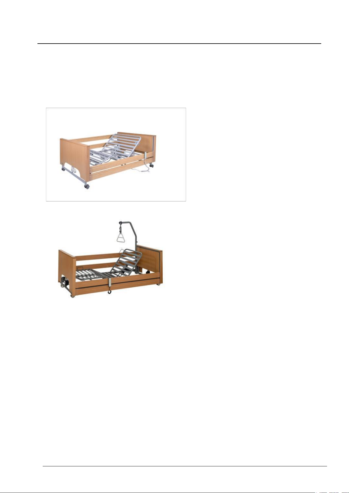
VitalFlex Homecare beds with 4-section bed platform motorized adjustment.
Backrest 0 –70°, legrest 0 –20°
VITALFLEX BED
•Features a full wood headboard and
footboard
•Mattress platform measures 90 x 200 cm (35”
x 78”)
•Height adjustment varies between 39.5 –82
cm (15.5” - 32”)
•Includes Dewert motor system
VITALFLEX LOW BED
•Features a full wood headboard and
footboard
•Mattress platform measures 90 x 200 cm
(35” x 78”)
•Height adjustment varies between 22-64.5 cm
(8.5” x 25”)
•Includes Limoss motor system

Page 5 of 35
ViftalFlex Beds User Manual
Foreword
Dear Customer,
The team at Vital Mobility would like to thank you for the confidence you have placed in our VitalFlex
Homecare bed models 1.
With your decision to buy a care bed from Vital Mobility, you have acquired product with a
high degree of functionality and the highest level of safety. With the VitalFlex bed you have
purchased we can guarantee maximum comfort and a professional standard of care.
All beds are thoroughly tested by our company before leaving our premises.
The care bed delivered to you left our facilities in perfect condition.
When you accept delivery of a VitalFlex bed, users and caregivers take on the responsibility
of properly using the device according to the purpose intended.
This instruction manual informs you (as the operator) and other users, about the functions and
safe handling of this care bed on a daily basis.
Please always keep the instruction manual near the care bed.
We are confident that this product will play an important role in daily caregiving while bringing safety
and comfort to you or a loved one.
Yours sincerely,
The Vital Mobility Team
1 The instruction manual is valid for bed models VitalFlex and VitalFlex Low

Page 6 of 35
ViftalFlex Beds User Manual
1 General Information
Before putting the bed into service for the first time:
Read through this instruction manual closely from start to finish. Please note
the various safety instructions that must be observed. Clean and disinfect your
VitalFlex care bed before using it for the first time.
VitalFlex beds bear the CE mark and meet all safety and functionality requirements.
These homecare beds were tested according to the international standards which
contain the safety requirements for medical products.
These safety requirements can only be met however, if the user understands proper
usage of the bed and accessories before using it.
Please observe the legislation in your country.
1.1 Explanation of the Symbols Used
Read information with this symbol carefully and urgently follow instructions.
This information is safety-relevant
This symbol indicates hazards due to electrical voltage. There is mortal
danger!
This symbol indicates general hazards. There is danger to life and health
Conformity mark in accordance with the Medical Device Directive (93/42 EEC)
IPX4 The electrical equipment is splash-proof
Symbol for Protection Class II device, double shock-proof
Symbol for type B device according to DIN EN 60601-1
This care bed may only be used indoors
This product must be disposed of in a separate refuse collection in the European
Union. Do not dispose of as normal domestic waste
Symbol for direct current
Symbol for alternating current

Page 7 of 35
ViftalFlex Beds User Manual
Maximum permissible load.
Maximum patient weight.
Read instructions
1.2 Definition of the Groups of Persons involved
Operator
An operator is any natural or legal person who uses the care bed or on whose instruction
it is used (e.g. nursing homes, specialized retailers, health insurance companies, medical
suppliers).
Users
Users are persons who because of their vocational training, experience or briefing are
authorized to operate the care bed or to carry out work on it or are instructed in handling
the bed. Furthermore, the user can recognize and avoid potential dangers and assess the
clinical condition of the patient.
Patient / Occupant
Persons in need of care, handicapped or infirm and occupying a care bed.
Qualified Personnel
Qualified personnel are employees of the operator who because of their vocational
training or briefing are entitled to deliver, assemble, disassemble, and transport the care
bed. In addition, these persons are instructed in the cleaning and disinfection regulations
for the care bed.
2 Intended Purpose
2.1 Intended use and application environment
This VitalFlex bed is intended for accommodating patients or occupants (with body mass
≥150 cm to max. 170 kg/375 lbs.) in residential homes, nursing homes and in care in
the home and may only be used under the conditions for use described in this
Instruction Manual.
It is used to alleviate or compensate for handicaps or disabilities and to facilitate the
working conditions for the caregiver.
Any other use shall be regarded as non-compliant with the regulations and is excluded
from any liability.
Attention: The care bed is not designed for use in hospitals.
The care bed is not suitable for medical electrical applications which involve
intravascular or intracardiac processes with the patient.

Page 8 of 35
ViftalFlex Beds User Manual
The care bed is not designed for the transport of patients.
Under certain conditions the care bed can be used for other medical purposes with
medical appliances such as antidecubitus mattresses, aerators, alimentation systems etc.
In this case all bed functions must be locked out with the nurse key on the handset
for safety. The medical appliance providers are liable for the compliance of the device
with the directives of IEC 60601-1-1.
If other electrical devices are used in the bed and to prevent the risk of an electrical
shock, protective measures and precautions must be established to prevent
power cords from being trapped and squeezed in movable parts of the bed.
2.2 Non-Intended Use
All uses deviating from the intended purpose, which may also be hazardous as a result.
This includes for example:
•Loading the care bed beyond the safe admissible working load (see section 13.1 and
identity label on bed frame)
•Operation of the care bed by patients or occupants who have not been instructed in
its use
•Use of the care bed for children
•Attempting to move the care bed when it is in a braked position
•Use of the care bed on a non-horizontal surface (max. incline 5°)
3 General Regulations for Users
The care bed must only be used for the purpose intended. When setting up, operating,
and using the care bed, respect the regulations in your country and the general
recognized rules of technology and the occupational health and safety and accident
prevention regulations.
If the care bed is in a faulty state, in which the patient/occupant, care personnel or third
persons could be endangered, operation may not be started or immediately discontinued.
3.1 Qualification of Users
The care bed must only be operated by persons who have the corresponding training or
experience to enable them to handle the care bed correctly.
4 Safety Instructions
4.1 General Safety Instructions
During the briefing, specific attention must be drawn to any potential dangers which can
occur despite correct operation. Before putting the care bed into service for the first time,
the Instruction Manual must be read conscientiously and in detail by the user / care
personnel.

Page 9 of 35
ViftalFlex Beds User Manual
When operating the adjusting functions, there must not be any objects or people's limbs
in the plane of movement of the care bed. Risk of crushing!
Do not sit on the leg section of the bed when operating the raise function.
Ensure that children cannot operate the control system and check if pets are under the
bed before operating any of the functions. Never store anything under the bed.
If the physical or mental state of the patient requires it, the handset should be locked on
the reverse side of the handset when not in use (nurses' key). See detailed description of
the locking operation at section 7.3. (it may be advisable to keep the handset out of reach
of such a patient to avoid the risk of strangulation with the handset cord).
Adjustments to the bed must only be carried out by suitably instructed persons or in the
presence of an instructed person.
When the side guards are used, the following instructions must be particularly adhered to:
· Use only approved side guards supplied as option by Vital Mobility. See
dimensions suitable at section 13.1
· Only suitably instructed personnel can operate the side guards
· Side guards must only be adjusted to be either fully up and locked in place or fully
down
· Lower the side guards smoothly and take care not to let them drop down
· When operating the adjusting functions, the patient's limbs must not protrude beyond
the mattress base or touch the side guards
· The side rail guards are only designed to prevent a person falling out of the bed;
under no circumstances should they be climbed or leaned on
· When lowering the rails take care not to drop them, they should be lowered carefully
· The side guards only provide protection against rolling out of the care bed if the
backrest and lower leg adjustments are in the horizontal position
· The side guard height from the top of the mattress in uncompressed condition must
be at least 220 mm. If the height is less than 220 mm increase the side guard height
with a high side rail kit
· The gap between two side guard rails or between lower side rail and bed platform
must be less than 12 cm
· During use ensure that the side guards are level
Unplug the mains plug from the socket before moving the care bed and take care to avoid
dragging the mains plug across the floor when moving the bed.
The mains plug must always remain accessible to enable immediate cut-off by
unplugging the mains plug from the wall socket in case of emergency.
The mains cable must be free and not caught up in anything, as it gets carried along
when the bed height is adjusted. Otherwise, the mains cable may be torn out of its strain
relief and damaged. In addition, the mains plug may be pulled out of its socket and
electric leads exposed as a result.
If the mains cable or the mains plug are damaged, the relevant part must be replaced.
This work should only be carried out by the manufacturer or authorised professionals.
When connecting the mains plug do not use multiple sockets since liquids may penetrate
into these (fire hazard and electric shock).

Page 10 of 35
VitalFlex Beds User Manual
Before cleaning and disinfection, the mains plug must be unplugged and hung up safely.
Plugs for the handset and the motors which are inserted into the mattress base control
box and motor unit must remain plugged in. This is necessary to prevent water ingress
into the control box.
When the bed is stationary the castors must always be in the braked position. If the
castors are not braked, the bed can move when the occupant gets in and out of bed,
since the occupant uses the bed for support. Injury can result if the care bed rolls away.
To move the care bed, the brake on all four casters must be released and the mattress
base be adjusted to the lowest horizontal position.
The maximum duty cycle and the safe working load must not be exceeded as otherwise
safe operation cannot be guaranteed (please refer to Technical Data).
The bed must not be used in rooms where there is a risk of explosion.
The bed must only be taken apart if there is no patient or occupant in it.
4.2 Safety Information for the Operator
With the help of this Instruction Manual, instruct each user in the safe operation of this
care bed before it is put into service for the first time.
Advise the user of any hazards which may occur if not handled correctly.
Only persons who have been properly instructed may operate this care bed. This also
applies for persons who only operate the care bed on a temporary basis.
These homecare beds are Class I active medical products according to the MDD.
Please observe your obligations as the operator.
Read section 10.2 for this purpose.
4.3 Safety Information for the User
Ensure that the operator instructs you in the safe operation of this bed.
In addition, pay particular attention to the general safety information as described in 4.1.
Adjustments of the bed must only be carried out by suitably instructed persons or in the
presence of an instructed person.
Make sure that the mattress base has travelled to its lowest position before leaving the
patient unattended. This will minimize the risk of injury to the patient when getting in or
out of bed.
If there is a suspected fault or damage, unplug the mains plug from the socket. Clearly
mark the care bed as “Out of Order” and take it immediately out of service. After that
please inform the person in charge without delay.

Page 11 of 35
VitalFlex Beds User Manual
4.4 Cleaning and Disinfection
Before cleaning and disinfection, the mains plug must be unplugged and hung up safely.
Plugs for the handset and the motors that are plugged into the control box must remain
in their sockets. This is necessary to prevent water from getting into the control system.
Do not immerse electrical components in water but just wipe them with a damp cloth.
The electrical components must not be cleaned with a high-pressure cleaner or a water
jet. Only disinfection by wiping is allowed.
Always wear waterproof gloves when cleaning and disinfecting to avoid skin irritation.
Attention: In the event of disinfection by spraying on a large scale with products
containing alcohol there is a danger of explosion and fire.
4.5 Servicing and Maintenance
Servicing work must only be carried out by persons who have at least read the safety
regulations and are qualified to do so.
A technical check and/or safety inspection must be conducted at least once a year and
after a lengthy break in use and before each further use. There is section 10.2 for this
purpose.
Any defects, damage or signs of wear must be rectified without delay. Only original spare
parts from Vital M o bi l i t y may be used, otherwise all guarantees, or warranties will be
excluded.
Please check all fixings on your bed at least once a month. Pay special attention to side
rail components and sleeping platform connections.
The 9V block battery is the energy store for electrical emergency lowering in the event of
a power failure. The energy store is sufficient for one emergency lowering at the most
and must then be replaced. If the expiry date of the battery has elapsed, then it must be
replaced immediately. Since batteries are subject to self-discharging, it is recommended
that the battery is replaced every two years if not used. It must be ensured that it is a
type 6LR61 alkaline manganese battery and not any other type. Used batteries must be
disposed of in an environmentally compatible way.
4
.
6
A
cce
ss
o
r
i
e
s
The optional accessories available include a patient's lifting pole of which the safe working
load is 80 kg (176 lbs) and must not be exceeded. The patient's lifting pole may only be
used within its admissible adjusting range which is defined by the sleeve on the bed.
Otherwise the bed can tip up and result in serious injury.
Use only mattresses compatible with the supplied side guard system. The dimension
between mattress upper surface in uncompressed condition and top edge of the upper

Page 12 of 35
VitalFlex Beds User Manual
side rail must be 22 cm minimum. If this dimension is less than 22 cm, a high side rail kit
should be fitted. In general mattresses of 12 cm (5”) height are suitable.
4
.
7
E
l
ec
t
r
o
m
a
gn
e
t
i
c
C
o
m
patibi
l
ity
Regarding their emitted interference and interference resistance the electric motor units
comply with the requirements of EN 60601-1-2:2007 (see section 13.7). But it is possible
that electrical devices interfere with each other. In this case switch off the care bed for a
short time or remove the interference source.
4
.
8
S
to
ra
g
e
If the care bed is stored for a lengthy period, the 9V block battery should be removed, as
otherwise it would be subject to a higher rate of self-discharge.
4
.
9
Serv
i
ce
L
i
f
e
a
n
d
Disp
o
s
al
The normal service life for care beds in domestic use is approx. 5 years. The care bed
must not be disposed of as normal domestic waste after its service life has expired. To
ensure that it is disposed of in an environmentally compatible way please get in touch
with Vital Mobility.
5
S
to
ra
g
e
an
d
Tr
ans
p
o
r
t
Due to its modular construction the care bed can be easily transported. This is made
possible by a transporting device. The transport rack integrated in the care bed can be
maneuvered in very small spaces due to the bed's casters.
Cover
State as delivered
Care bed in the
transport device

Page 13 of 35
VitalFlex Beds User Manual
6 Installation andCommissioning
6.1 Pre-
installation inspection
On delivery and before installation check that the packaging is undamaged. Report any
visible damage to the transport company immediately. After unpacking check that
all
following parts are present:
Mattress base halves backres
t
/
foot
section He
i
ght-
a
d
j
u
s
ta
b
l
e
bedend
panels
pieces
X
Backrest section with mounted backrest actuator and control box
X
Leg rest section with mounted knee-break
actuator
X
2 x height adjustable bed ends with mounted actuators and casters
X
(4a) Monkey pole (optional) with
triangular handle and webbing strap (4b)
X
(5a) power supply with cord and plug
X
(5b) handset with locking device
X
(6a) 4 pc. wooden sideguards and 8 plastic end caps (6b) in a separate package
X
Instruction manual
ATTENTION:
DEWERT
Motor system will be as
below:
Motor for lifting Motor for backrest Motor for footrest Control box Handset

Page 14 of 35
VitalFlex Beds User Manual
6.2 Removal from the Transporting Device
Lift the cover from the whole bed unit including the transporting device.
Please do not dispose of the cover! This can be used again as a dust cover in the
event that the care bed is later stored in the transport rack.
Cut through the packaging strips using a side
cutter or a pair of scissors
First lift the mattress base section for the head-end out of the transporting device and
then lift out the mattress base section for the foot-end of the bed.
2. Mattress base section
for the head-end
1. Mattress base section
for the foot-end
Remove the cable ties from the handset and the mains cable.
Handset
Mains cable, Caution!
Do not damage the cable!
Remove the height-adjustable head and foot end panels from the transporting device. To
do this, release the spring-loaded catches that are later used to fix the height-adjustable
head and foot end panels to the mattress base.
Pull out and turn
through 90°
Mounting lugs for
the mattress base

Page 15 of 35
VitalFlex Beds User Manual
6.3 Assembly of the Care Bed
Remove the cable tie from the backrest motor (including the attached mains adapter) and
from the thigh rest adjustment motor. Attention! Keep firmly hold of the motor in
question when loosening the cable tie, because the motors can fall when they are not
secured in place (with safety bolts).
Backrest motor Thigh rest adjustment motor
Please note
The actuators arrive in the
transport position.
If the bed is operated with
the actuators in this position
it will result in the
premature failure of the
actuator/sleeping platform.
Remove the safety bolt then
move the actuator into
position and re install the
safety bolt.
Connect the fork heads of the motor units with the terminal links on the mattress base.
To do so, use the safety bolt which is inserted into the hole for the terminal links. To losen
the bolt, throw the safety lever. Attention: The safety lever must be locked
again after connecting the motor and the mattress base.
Backrest motor situation Thigh rest motor Final secured state
Mattress base
terminal link
Safety bolt Safety lever,
fixed in place
Connecting the two halves of the mattress base
Star knobs M8
(4x)

Page 16 of 35
VitalFlex Beds User Manual
Now fit the two halves of the mattress base together and secure them using the star
knobs provided. After assembling the mattress base halves, tighten the star knobs.
Now lay the mattress base on the floor and attach the first of the bed ends to the
mattress base. To do this, apply the brakes on the bed casters by pressing the brake
pedal and then release the spring-loaded catches (see 6.1) at the height-adjustable head
and foot end panels so that the mattress base can be slotted onto the mounting lugs.
Mounting lugs for
the mattress base
Caster
Foot pedal locked
Mattress base Spring-loaded
catches
Snap the spring-loaded
catches back into place
on both sides
When securing the spring-loaded catches, ensure that the bolt locks into place in
the hole provided for it.
Spring-loaded
catches
The bolt of the
spring-loaded catch
must be securely
latched into the hole!
Now slot the mattress base into place on the second height-adjustable bed-end panel at
the other end of the bed.
Following *section* applies to the VitalFlex Standard Height Bed only:
*Do not lock the spring-loaded catches on this side just yet, because these must remain
open until the wooden side guards have been mounted. Now slide the (four) side guards
onto the location bolts of the side guard guides, resting the other ends of the side guards
on the mattress base at the other end of the bed.
Side-guard guide rail
Location bolts for the
side guards

Page 17 of 35
VitalFlex Beds User Manual
Now, at the end of the bed where the side guards have not yet been pushed onto the
location bolts, lift one corner of the mattress base off the mounting lug and pull the
mattress base back far enough to allow you to push the side guards onto the location
bolts.*
Pull back the bed
end panel with
mounting lug
Slide both side
guards onto the
location bolts
Lift one corner
of the mattress
base slightly
Push the end panel back
towards the mattress base
and place the base onto the
mounting lug
Fix both the spring-loaded
catches securely back in
place
Now, with the side guards slotted into place, the end panel can be pushed back up
to the mattress base and secured with the mounting lug. Repeat this procedure on the
other side of the bed with the remaining two side guards and then fix the two spring-
loaded catches securely to the mattress base.
Now connect the height adjustment motors and the thigh rest adjustment motor to the
mains power supply. First remove the plug cover by unscrewing the two fixing screws.
The power supply cables for the height adjustment motors are wound around its housing.
The backrest motor is supplied already plugged in. After you have inserted all the plugs,
screw the plug cover back onto the power supply unit housing.

Page 18 of 35
VitalFlex Beds User Manual
Plug cover
Fixing screws
for plug cover
Unwind the cable of the
electric motor!
Plug in height adjustment actuators (yellow)
Thigh rest motor, backrest motor, handset and power supply are
supplied already plugged in!
Power supply includes: Mains plug-
cable to Safe Low Voltage Transformer.
Now remove the transportation safety ties from the mattress base by cutting through the
cable ties with a side cutter or a knife.
Transportation safety
device for the thigh rest
Transportation safety
device for the backrest
Now assemble the patient's lifting pole bow (optional) and insert this into the lifting pole
bow holder in the mattress base. Ensure that the cylinder pin locks into place in the
pocket of the lifting pole bow holder.
Attention: the patient’s lifting pole bow must not be used outside the catch mechanism,
as otherwise the care bed will not be stable and can tip up.
Lock cylinder pin into
place in the pocket!
Fit together
Lifting pole sleeve
Screw star knob into
drillhole and tighten!

Page 19 of 35
VitalFlex Beds User Manual
trap over the first pin
the triangular handle
Slide the loop of the webbing s
location by pulling down tightly
of the lifting pole and test its secured
Attention: Fix the loop of the webbing strap
only between these two bolts!
Triangular
handle
Connecting the care bed to the mains socket
Unwind the mains cable wound up under the mattress base.
Strain relief for mains
cable
Bracket for winding up the
mains cable
Unwind the wound-
up mains cable!
Lay the coiled cable across the crossbeam from the head or foot end as shown in the
picture. This reduces the risk that the mains cable is driven over when the bed is moved.
Always avoid driving over the mains cable!
Lay the mains cable
across the crossbeam
Plug the mains plug into the socket.
The mains plug must always remain accessible to enable immediate cut-off by
unplugging the mains plug from the wall socket in case of emergency.
The electrical adjustment motors are now ready for use.

Page 20 of 35
VitalFlex Beds User Manual
6.4 Placing into service
Make sure that all assembly steps have been carried out according to chapter 6, sections
6.1 and 6.2
Do a safety check according to chapter 10, section 10.2 after assembly.
Clean and disinfect the bed as described in chapter 8 before putting into service and
before each further use.
6.5 Disassembly of the Care Bed
Unplug the mains plug from the socket before disassembly.
Disassembly of the care bed is carried out in reverse order of assembly.
This manual suits for next models
1
Table of contents
Other Vital Medical Equipment manuals
Popular Medical Equipment manuals by other brands

Innovative Neurotronics
Innovative Neurotronics The WalkAide System Clinical manual

Image Diagnostics
Image Diagnostics ilex32 4K Installation and operation manual

EKO Device
EKO Device CORE user guide

mk-dent
mk-dent AM1014 instruction manual

Omron
Omron COMP A-I-R Pro NE-C29-RU instruction manual

Bionic
Bionic DreamLine Instructions for use