Vitec Multimedia FIM-102D User manual

FIM-102D MATRIX FIBER INTERFACE
INSTRUCTION MANUAL

FIM-102D Matrix Fiber Interface Instruction Manual
©2004 Vitec Group Communications
All Rights Reserved
Part Number 810319
Vitec Group Commmunications, Inc.
4065 Hollis Street
Emeryville, CA 94608-3505
U.S.A.
A Vitec Group Company
Clear-Com is a registered trademark of Vitec Group Communications.
The Clear-Com Logo is a registered trademark of Vitec Group Communications.

FIM-102D FIBER INTERFACE i
CONTENTS
OPERATION............................................................................................................................................ 1-1
Description .................................................................................................................................................................1-1
Connecting Intercom Stations To The Central Matrix ..................................................................................1-1
Connecting Interface Modules To The Central Matrix..................................................................................1-5
Using The FIM-102D In Conjunction With The EF-1M As A Stand-Alone Party Line Extender.......1-6
FIM-102D Two Fiber Configuration.....................................................................................................................1-6
FIM-102D Front Panel Connectors And Lights..................................................................................................1-8
FIM-102D Rear Panel Connectors.........................................................................................................................1-10
INSTALLATION ........................................................................................................................................ 2-1
Unpacking...................................................................................................................................................................2-1
Installing and FIM-102D Unit In A Rack .............................................................................................................2-2
Installing Fiber Optic Cable.....................................................................................................................................2-2
Maximum Fiber Lengths.....................................................................................................................................2-3
Connecting Fiber Optic Cable To The FIM-102.................................................................................................2-5
Connecting Audio/Data Cables To The FIM-102D ..........................................................................................2-7
CAT-5 Cable Pinout Diagram............................................................................................................................2-8

ii FIM-102D FIBER INTERFACE
MAINTENANCE........................................................................................................................................ 3-1
Troubleshooting Tips ...............................................................................................................................................3-1
Preventative Maintenance ........................................................................................................................................3-3
GLOSSARY............................................................................................................................................... 4-1
SPECIFICATIONS ..................................................................................................................................... 5-1
CLEAR-COM LIMITED WARRANTY .......................................................................................................... 6-1
Factory Service...........................................................................................................................................................6-2
Warranty Repair.........................................................................................................................................................6-3
Non-Warranty Repair ...............................................................................................................................................6-3

FIM-102D FIBER INTERFACE 1-1
1OPERATION
DESCRIPTION
With a Clear-Com FIM-102D System, you can connect Clear-Com intercom stations or interfaces to the central
Matrix using fiber-optic cables at distances of up to 12 miles (20 km).
The system consists of one FIM-102D at the Matrix-frame end and another FIM-102D unit at the Matrix-station end.
Connecting the pair of interfaces with fiber rather than with the standard 4-wire twisted copper, gives you advantages
such as increased security from electromagnetic and RF interference, flexibility in equipment placement, ease of
maintenance and often, reduced cost.

1-2FIM-102D FIBER INTERFACE
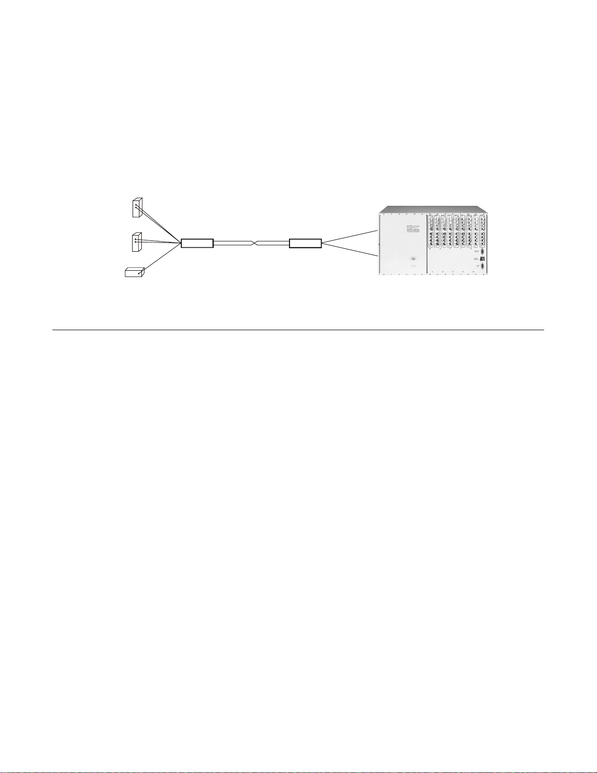
CONNECTING INTERCOM STATIONS TO THE CENTRAL MATRIX
The Clear-Com FIM-102D system transmits audio and data signals from 1 or 2 intercom stations or interfaces to the
Matrix frame through the process illustrated in Figure 2.
Figure 1: Connecting Intercom Stations to the Central Matrix

FIM-102D FIBER INTERFACE 1-3

1-4FIM-102D FIBER INTERFACE
1. Matrix Plus intercom stations transmit analog audio signals and digital data signals to the first FIM-102D unit via
copper cable terminated with RJ-45 connectors.
2. The first FIM-102D unit converts the analog audio signals to digital audio signals through an analog-to-digital
converter (ADC) located on the FIM-102D unit’s main circuit board.
3. The first FIM-102D unit then multiplexes (combines) the digital audio signals with the already digital data signals.
4. The first FIM-102D then converts the multiplexed digital signal into an optical signal.
5. The first FIM-102D then transmits the optical signal over up to 12 miles (20 km) of fiber-optical cable to the
second FIM-102D unit, where a similar but reverse process occurs to convert the signal back to its original format.
6. The second FIM-102D unit converts the received optical signal to a digital signal.
7. The second FIM-102D then “demultiplexes” (separates) the digital signal back into it’s separate audio and data
signals for each intercom unit.
8. The second FIM-102D then converts the digital audio signals for each intercom station to analog audio signals by
sending the signals through a digital-to-analog converter (DAC) located on the FIM-102D unit’s main circuit board.
9. The second FIM-102D unit then transmits the analog audio and digital data signals for each intercom station to the
central Matrix over copper cable terminated with RJ-45 connectors.

FIM-102D FIBER INTERFACE 1-5
10. The central Matrix receives the intercom stations’ audio and data signals in the same format in which they were
originally sent by the Matrix Plus 3 intercom stations.
WARNING: Always use extreme caution with fiber-optic equipment. Never look directly into the light port or into
the end of the optical fiber while either FIM-102D unit is operating. Even if you do not see visible light, eye
damage is possible.
CIRCUIT DESCRIPTION
Analog-to-Digital Converters High speed analog-to-digital converters for each audio channel.
Multiplexer Sequentially presents two RS-422 digital inputs and two digitized audio signals from the A/D converters to the
optical output driver.
Demultiplex-er Takes sequential digital signals from the pin diode and separates them into 4 separate lines: two to the D/A
converters and two to the RS-422 transmitters.
Digital-to-Analog Converters Hi
g
h speed di
g
ital-to-analo
g
converters for each audio channel convert the di
g
itized audio si
g
nal back to analo
g
audio.
1-6FIM-102D FIBER INTERFACE
CONNECTING INTERFACE MODULES TO THE CENTRAL MATRIX
With a pair of FIM-102D units you can also remotely connect Clear-Com rack-mounted Matrix interface modules to
the central Matrix. For example, using a Clear-Com CCI-22 dual party-line interface at one end, you can connect two
independent, external 2-wire party line systems to the central Matrix from a distance of up to 12 miles (20 km). Or,
with a Clear-Com TEL-14 Telephone Interface Module, you can send telephone audio to the central Matrix over a
secured interference-free fiber-optic line. By using a Clear-Com FOR-22 4-wire interface module, you can send 4-
wire audio plus transmit keying over a fiber-optic line. You can also use a Clear-Com EF-1M to interface 2-wire
Clear-Com or RTS party lines to the central Matrix over a fiber-optic link.
Figure 2 shows a system with connected interface modules.
FIM-102D FIM-102D
CCI-22 Interface
TEL-14 Interface
Connects two 2-wire
party-line circuits
Connects 2 tele-
phone lines
EFI-M Interface
Connects 2-wire
party-line to matrix
or other 4-wire devices
or
or
Figure 2: Connecting Interface Modules to the Central Matrix

FIM-102D FIBER INTERFACE 1-7
USING THE FIM-102D IN CONJUNCTION WITH THE EF-1M AS A STAND-ALONE PARTY LINE EXTENDER
Using a Clear-Com EF-1M at each end of a FIM-102D set, you can extend Clear-Com or RTS 2-wire party line
intercoms over a fiber-optic link independent of a Matrix intercom system.
FIM-102D FIM-102D
EFI-M Interface
Clear-Com
or RTS 2-wire
party-line
EFI-M Interface
Clear-Com
or RTS 2-wire
party-line
Figure 3: EF-1M and FIM-102D as Party-Line Extender
FIM-102D Two-Fiber Configuration
In a standard two-fiber system, identical FIM-102D units are used at each location. The units both transmit at 300 nm
on ST connector “Fiber Out” and receive the 300 nm signal on ST connector “Fiber In”. They are connected by the
two fibers so that the optical output of each box is connected to the optical input of the other. In both one- and two-
fiber systems, the input of channel 1 on one unit becomes the output of channel 1 on the other unit and vice versa.
The two FIM-102D units in the two-fiber version are identical, so the units are interchangeable.

1-8FIM-102D FIBER INTERFACE
FIM-102 One-Fiber Configurations
These configurations may be offered at a later date.
FIM-102D FIBER INTERFACE 1-9
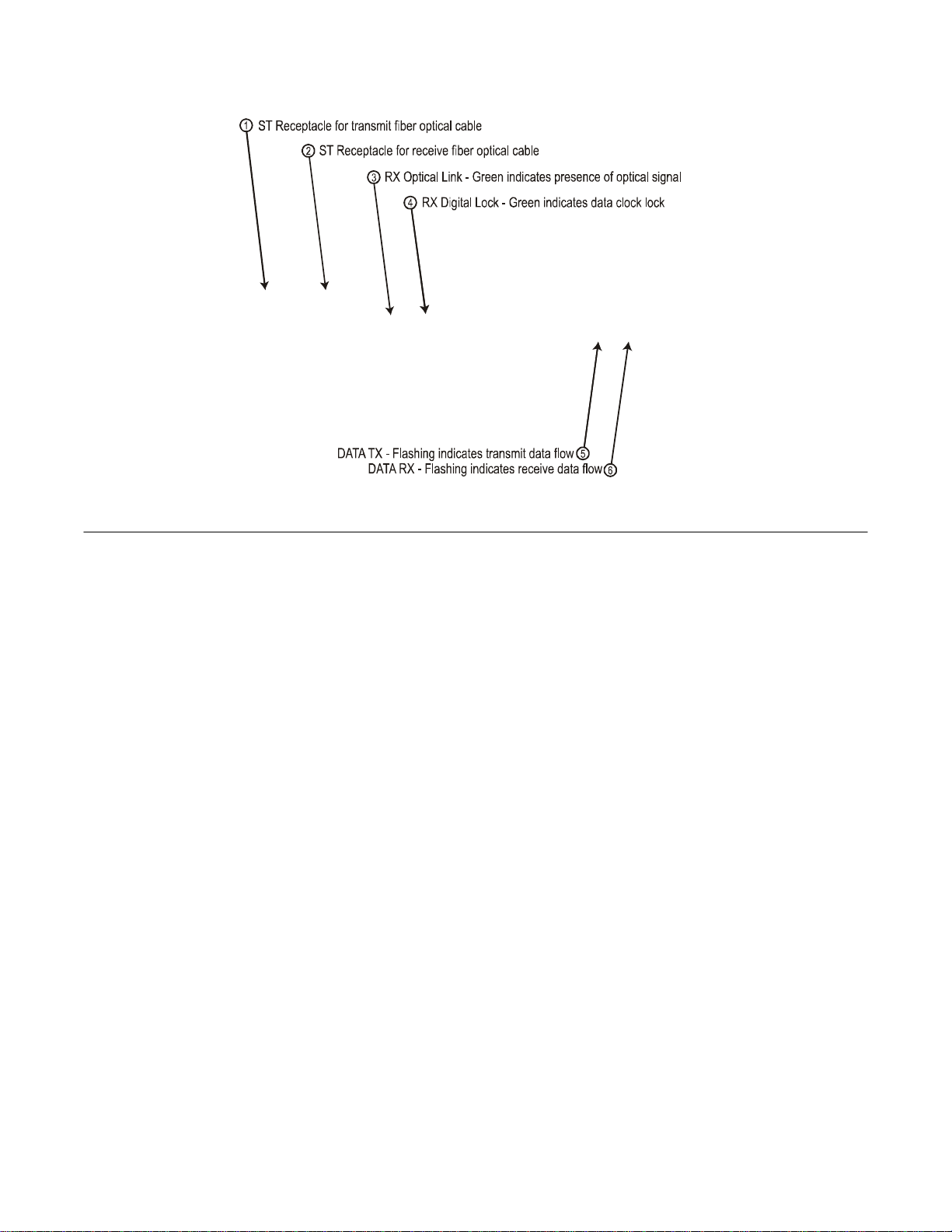
FIM-102D FRONT PANEL CONNECTORS AND LIGHTS
Figure 4: Front Panel of FIM-102D Unit

1-10FIM-102D FIBER INTERFACE
Fiber Out
Fiber Optic ST type receptacle for connection of transmit Fiber Optic Cable to other FIM-102D unit.
Fiber In
Fiber Optic ST type receptacle for connection of receive Fiber Optic Cable from other FIM-102D unit.
RX Optical Link
On (green) indicates presence of sufficient optical signal from other FIM-102D unit for communication.
RX Digital Lock
On (green) indicates presence of digital clock signal from other FIM-102D unit.
DATA TX
Flashing green indicates transmit data is flowing.
DATA RX
Flashing green indicates receive data is flowing.
FIM-102D FIBER INTERFACE 1-11
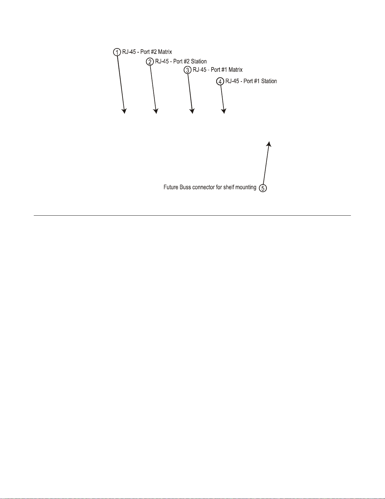
FIM-102D REAR PANEL CONNECTORS
Figure 5: Rear Panel of FIM-102D Unit

1-12FIM-102D FIBER INTERFACE
Port #2 Matrix
For Matrix end of FIM-102D link. Connect RJ-45 cord from here to Matrix port.
Port #2 Station
For Station end of FIM-102D link. Connect RJ-45 cord from here to Station or Interface.
Port #1 Matrix
For Matrix end of FIM-102D link. Connect RJ-45 cord from here to Matrix port.
Port #1 Station
For Station end of FIM-102D link. Connect RJ-45 cord from here to Station or Interface.
Future Buss connector
This connector is only used when FIM-102D is mounted in an optional multiple unit equipment shelf. The
shelf supplies power to the FIM-102D via this connector.

FIM-102D FIBER INTERFACE 1-13
Figure 6: FIM-102D Shown With Wall Mounted Power Supply

FIM-102D FIBER INTERFACE 2-1
2INSTALLATION
UNPACKING
When you receive your Clear-Com FIM-102D System, check to make sure you have received all components of the
system. The following items make up a Clear-Com FIM-102D:
•FIM-102D multiplexer/demultiplexer unit
•External power supply
You will require two FIM-102D sets to complete a circuit.

2-2FIM-102D FIBER INTERFACE
Inspect the units for mechanical damage. Inspect all electrical connectors for bent or damaged pins and latches.
Report any damage to the carrier and to Clear-Com Intercom Systems.
Leave the protective plastic caps on the optical connectors until it is time to attach the fibers to the units.
INSTALLING AN FIM-102D UNIT IN A RACK
A frame for mounting multiple FIM-102D units is available. Please contact the Clear-Com sales department for
information.
SELECTING AND INSTALLING FIBER-OPTIC CABLE
The person installing the FIM-102D units is responsible for providing the fiber optic cable runs. The FIM-102D will
operate with either Single-Mode or Multi-Mode Fiber Optic Cable. You will experience the best distance
performance when using Single-Mode cable as shown in Table 1.

FIM-102D FIBER INTERFACE 2-3
FIBER CORE DIAMETER MAXIMUM FIBER LENGTH
50 microns (multimode) 3 miles (5 km)
62.5 microns (multimode) 2 miles (3 km)
8 microns (single mode) 12 miles (20 km)
Table 1: Maximum Fiber Lengths
Mark or tag the optical fibers when they are pulled, carefully avoiding the fiber tip, so that their identity is known at
both ends. If there is confusion about the identity of the two fibers, shine a flashlight at one end of the fiber and look
for light at the other end.
WARNING: Do not use the FIM-102 optical output to identify cables. Never look directly into the end of the
optical fiber while either end of the system is operating. Even if you do not see visible light, eye damage is possible.
Table of contents
Other Vitec Multimedia Recording Equipment manuals


Popular Recording Equipment manuals by other brands


Lab:One Recordings
Lab:One Recordings ReQ 131 instruction manual

Sterling
Sterling HARMONY H224 owner's manual

Cochlear
Cochlear Baha 5 SuperPower Pairing and Streaming Manual

Rath
Rath 2100-Series Installation & operation manual

Friendly Songs
Friendly Songs Sound Module user guide

VDH Products
VDH Products ALFANET PC-INTERFACE 2 Series Hardware user manual