Vitronics Soltec myReflow User manual
Installation Guide
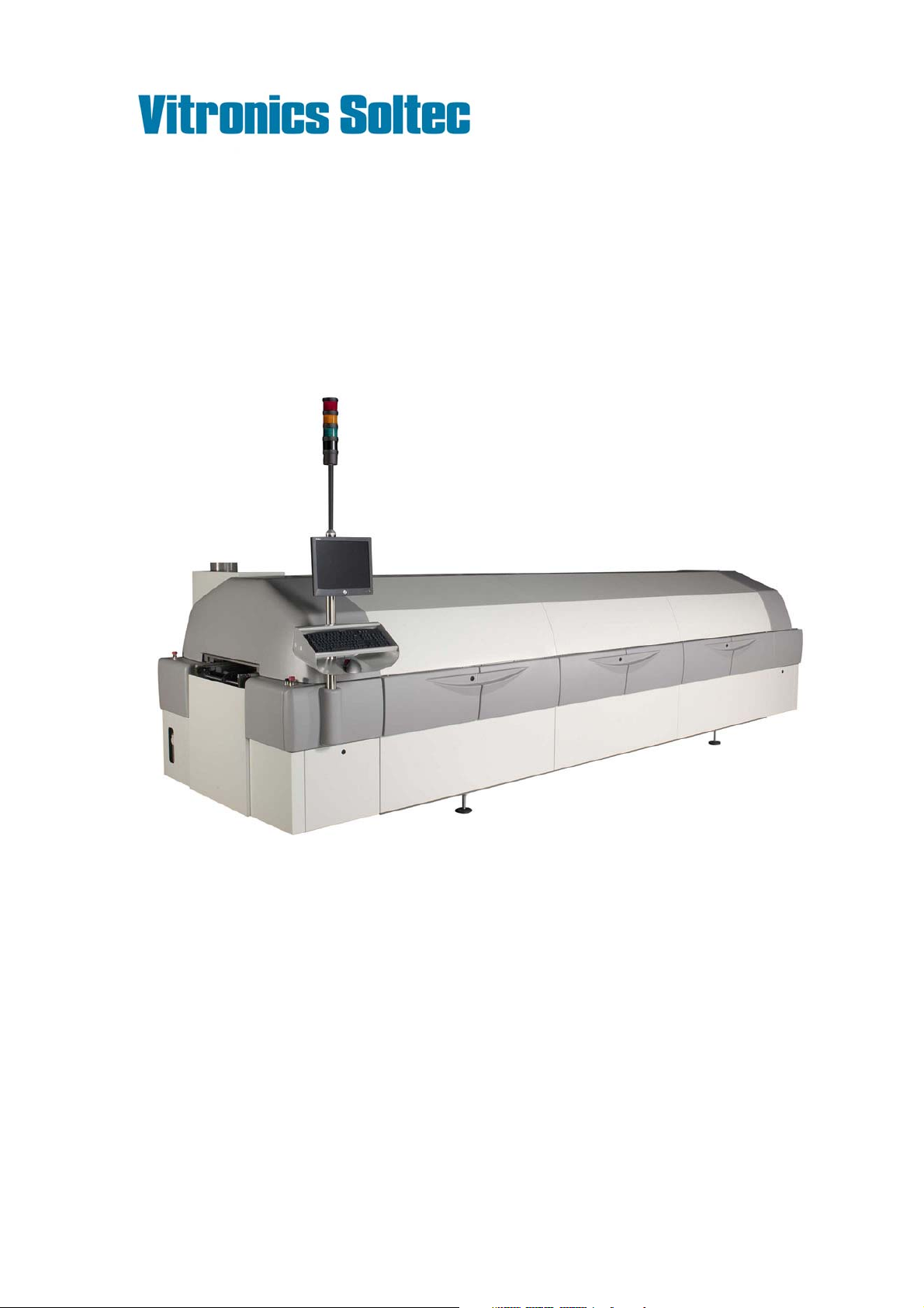
myReflow
Version 38.2.0.001
VITRONICS SOLTEC BV
Visit address Innovatiepark 12 - 4906 AA Oosterhout - the Netherlands
Mail address P.O. Box 143 - 4900 AC Oosterhout - the Netherlands
Telephone +31-162-483000
Fax +31-162-483269
www.vitronics-soltec.com

ii
Rights
COPYRIGHT 2009 VITRONICS SOLTEC BV
All rights reserved. No part of this publication may be reproduced, stored in a retrieval system, or transmitted in any form or by any
means, electronic, mechanical, photocopying, recording or otherwise, without the prior written permission of Vitronics Soltec BV.
This publication remains the property of Vitronics Soltec BV and may not be passed, loaned or given to any third party.
Vitronics Soltec BV reserves the right to make changes in design and specifications without notice.
EUROPE
VITRONICS SOLTEC BV VITRONICS SOLTEC GmbH
Innovatiepark 12 Udo-Lermann Str.10
4906 AA Oosterhout 97828 Marktheidenfeld
the Netherlands Germany
Tel. +31-162-483000 Tel. +49-9391-98820
Fax +31-162-483269 Fax +49-9391-988228
AMERICAS
VITRONICS SOLTEC Inc.
2 Marin Way
Stratham, New Hamphire 03885
USA
Tel. +1-603-772-7778
Fax +1-603-772-7776
ASIA PACIFIC
VITRONICS SOLTEC SHANGHAI VITRONICS SOLTEC (SUZHOU) Co. Ltd
Sales Office Manufacturing Plant
858 Zhujiang Lu 858 Zhujiang Lu
Building 2 Building 2
Suzhou New District, China 215129 Suzhou New District, China 215129
Tel. +86-21-5033-7855 Tel. +86-512-6841-3378
Fax +86-21-6360-9449 Fax +86-512-6841-3161
VITRONICS SOLTEC PTE LTD. VITRONICS SOLTEC KOREA
132 Joo Seng Road A-1001, Poonglim Iwant Bldg.
#03-01 Uniplas Building 255-1 Seohyun Dong,
Singapore 368358 Bundang Gu, Seongnam 463-862, Korea
Tel. +65-6484-3010 Tel. +82-31-783-7020
Fax +65-6484-1910 Fax +82-31-783-7021
VITRONICS SOLTEC MALAYSIA
8-2-5 Sunny Point Complex
Jalan Sultan Azlan Shah, Batu Uban,
11700 Penang, Malaysia
Tel. +60-4-658-4227
Fax +60-4-655-4227

Installation Guide myReflow iii
Preface
During the composition of this manual much attention is given to avoid errors
and mistakes. Also we aimed to give the contents a clear structure.
If during the use of this manual errors or incomplete descriptions are found, or
the reader considers that improvements are necessary to overcome any in-
accuracies, please inform us. We appreciate any comments which will help us to
improve this documentation.
For corrections or clarifications please contact:
1. By mail:
VITRONICS SOLTEC BV
HEAD OFFICE
TECHNICAL PUBLICATIONS
P.O. BOX 143
4900 AC OOSTERHOUT
THE NETHERLANDS
TEL NR. (31) - 162483000
FAX.NR. (31) - 162483285
OR
2. By e-mail:
hoosterhout@vsww.com

iv

Installation Guide myReflow v
Ta b l e o f C o n t e n t s
Preface iii
Table of Contents v
1 Safety features 1-1
1.1 General . . . . . . . . . . . . . . . . . . . 1-1
1.2 Symbols . . . . . . . . . . . . . . . . . . . 1-2
1.3 Required materials to work safe . . . . . . . . . . . 1-2
1.3.1 Ordering details . . . . . . . . . . . . . . 1-2
1.4 Hazards . . . . . . . . . . . . . . . . . . . 1-3
1.4.1 Flux vapours . . . . . . . . . . . . . . . 1-3
1.4.2 Hot surfaces . . . . . . . . . . . . . . . 1-3
1.4.3 High voltages . . . . . . . . . . . . . . . 1-4
1.4.4 Mechanical hazard. . . . . . . . . . . . . . 1-4
1.4.5 Eye hazard . . . . . . . . . . . . . . . . 1-4
1.4.6 Nitrogen . . . . . . . . . . . . . . . . 1-5
1.4.7 Fire hazard . . . . . . . . . . . . . . . . 1-5
1.4.8 Exhaust system . . . . . . . . . . . . . . 1-5
1.5 Precautions . . . . . . . . . . . . . . . . . . 1-6
1.6 Safety . . . . . . . . . . . . . . . . . . . . 1-7
1.6.1 Audible and visual indications . . . . . . . . . . 1-7
1.6.2 Precautions. . . . . . . . . . . . . . . . 1-8
2 Installation 2-1
2.1 General . . . . . . . . . . . . . . . . . . . 2-1
2.2 Transport . . . . . . . . . . . . . . . . . . 2-1
2.2.1 Symbols used . . . . . . . . . . . . . . . 2-1
2.3 Unpacking . . . . . . . . . . . . . . . . . . 2-2
2.3.1 Packet in crate. . . . . . . . . . . . . . . 2-2
2.3.2 Packed on wooden pallet . . . . . . . . . . . 2-2
2.3.3 Lifting with forklift . . . . . . . . . . . . . 2-3
2.4 Connections . . . . . . . . . . . . . . . . . 2-4
2.4.1 General . . . . . . . . . . . . . . . . . 2-4
2.4.2 Electrical connection . . . . . . . . . . . . . 2-4
2.4.3 Nitrogen connection . . . . . . . . . . . . . 2-4

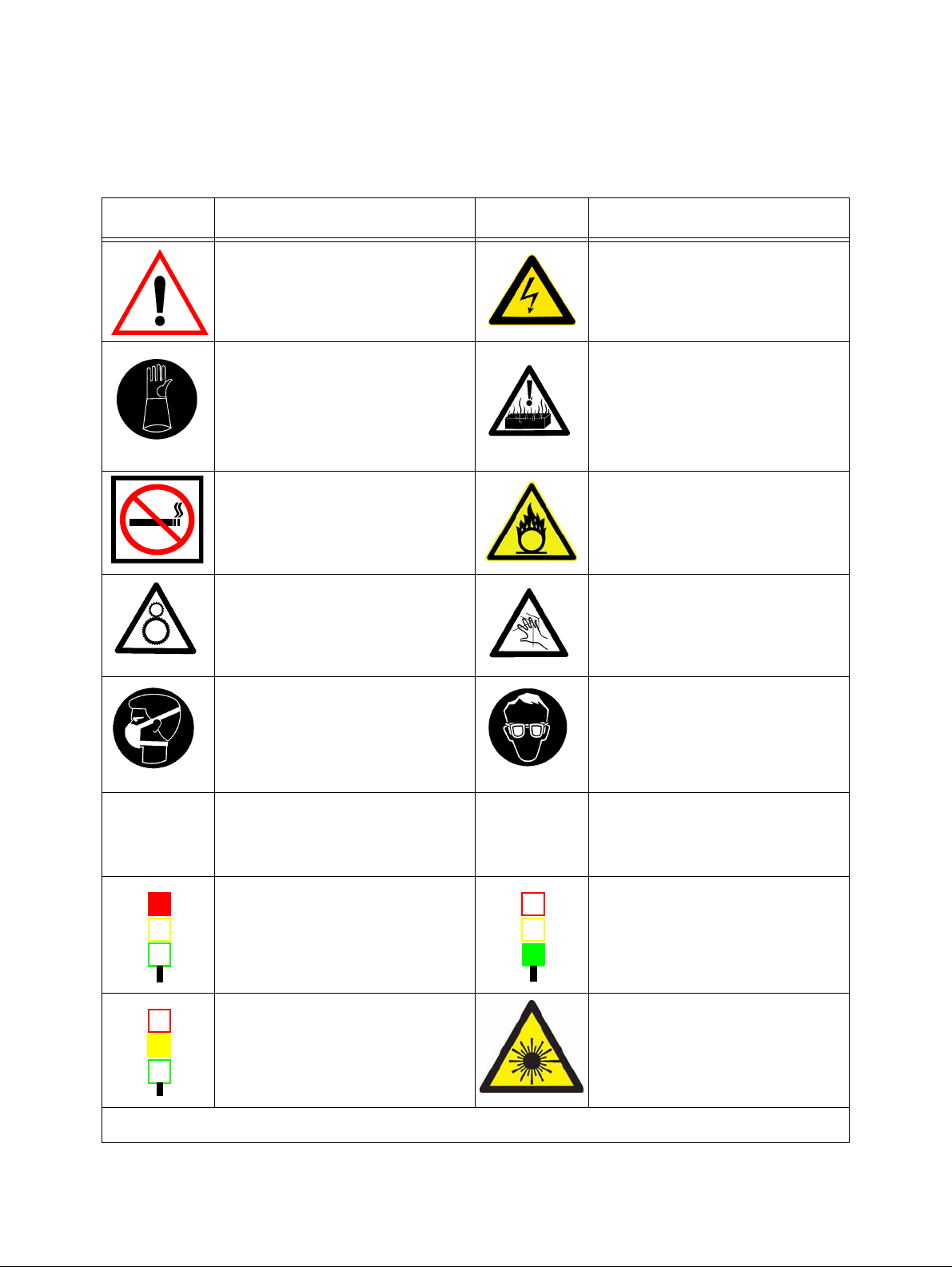
ICON DESCRIPTION ICON DESCRIPTION
Only Qualified personnel is allowed to work on the
equipment.
Never eat, drink or smoke while working on the
machine.
Wash thoroughly before eating, drinking or smoking.
High voltages are present on various parts of the sys-
tem.
Before working on the electrical circuit, turn main
power off and block the mainswitch with a padlock.
Always wear heat resistant gloves and protective
clothing when working on the machine.
If possible allow the machine to cool down before
starting working on the machine.
When burned, immerse in cold water immediately.
When the burn is severe, consult a physician as soon
as possible.
Always wear heat resistant gloves and protective
clothing when working on the machine.
If possible allow the machine to cool down before
starting working on the machine
When burned, immerse in cold water immediately.
When the burn is severe, consult a physician as soon
as possible.
No smoking or open fire near the machine.
Be sure a fire-extinguisher is in the surroundings of
the machine.
No smoking or open fire near the machine.
Be sure a fire-extinguisher is in the surroundings of
the machine.
All moving parts of the system, including pulleys,
belts, chains, coolingfans, sprocketwheels, vacuum-
doors and cylinders presents a potential danger.
Be careful with covers and doors. Always pay atten-
tion to opening and closing.
The vapours in the board preparation module are
chemical. When the board is heated, a noxious
vapour will be liberated. This vapour must be
extracted. Also the dust on the surface of the solder-
pot is dangerous when inhaled.
Avoid inhaling this vapours / dust by using mouth
protection.
When working on the machine, always protect your
eyes with safety glasses.
Nitrogen
N2
Follow the safety precautions and procedures
described in the Material Safety Data Sheet of
the Nitrogen supplier.
UPS
Uninterruptible
Power Source
When mainswitch is switched OFF for a longer
period, switch the UPS to OFF.
Signal light RED
- E-stop Active
Signal light GREEN
- Steady = Machine Run,
- Flashing slow = Machine not at setpoint, machine
stop
Signal light ORANGE
- Steady = Overload (outfeed full), Machine will
block,
- Flashing slow = Alarm
- Flashing fast = Critical alarm. Machine will block
LASER RADIATION
Do not stare into beam.
Class 2 Laser product.
Only applicable for Soldering machines
equipped with laser measurement systems.
If these rules are not observed it can cause personal injury and/or damage to the machine
SAFETY RULES
GENERAL INFORMATION

.

Installation Guide myReflow CHAPTER 1 1
Safety features 1
1.1 GENERAL
The myReflow Soldering System is designed and build only for soldering and handling printed cir-
cuit boards.
Safety features provides safe operating / working conditions for both the operator / maintenance-
man and the machine.
We urge all users, including operators and maintenance personnel, to read this chapter before
using the Vitronics Soltec soldering equipment.
We strongly recommend all personnel that will work with the Vitronics Soltec myReflow Solder-
ing System, to follow the official “VITRONICS SOLTEC TRAINING COURSE”, to ensure effi-
cient and safe operations.
Only qualified personnel that have joined and completed this training should work on the
machine.
VERSION 2009 June
SAFETY FEATURES
2CHAPTER 1
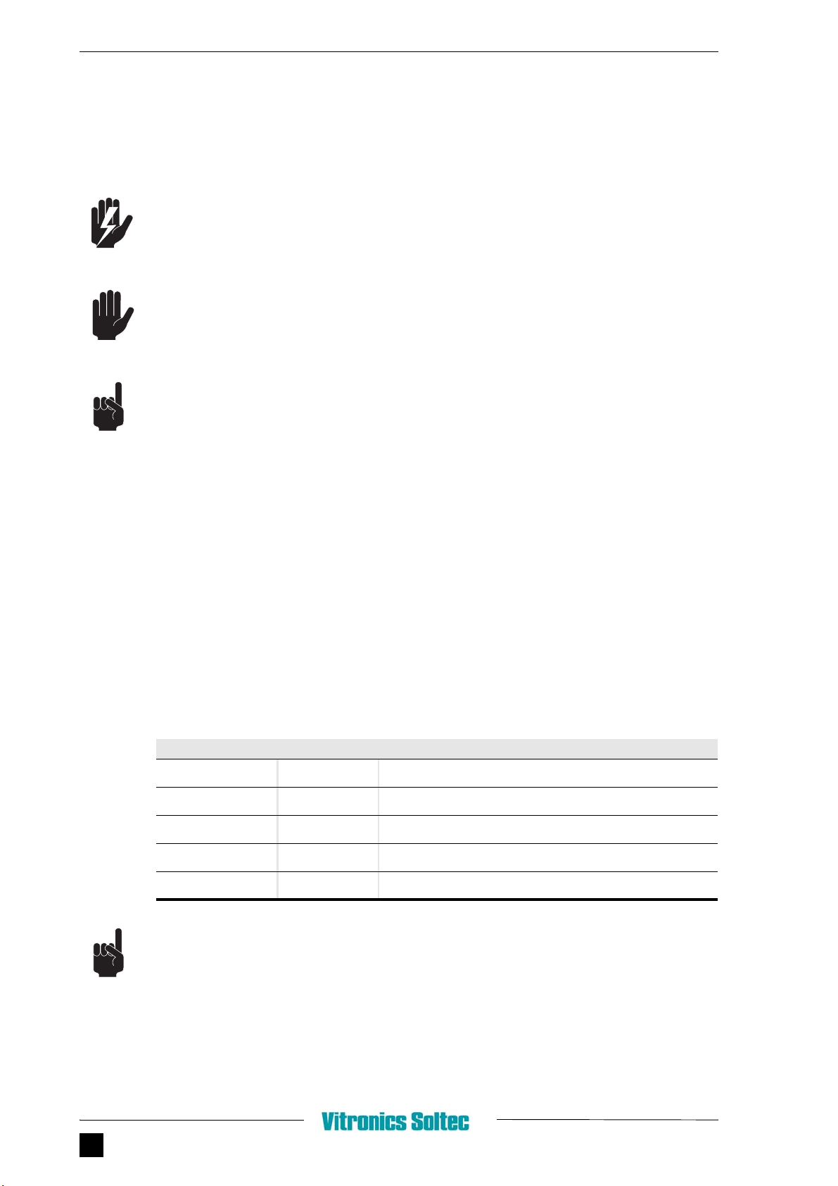
1.2 SYMBOLS
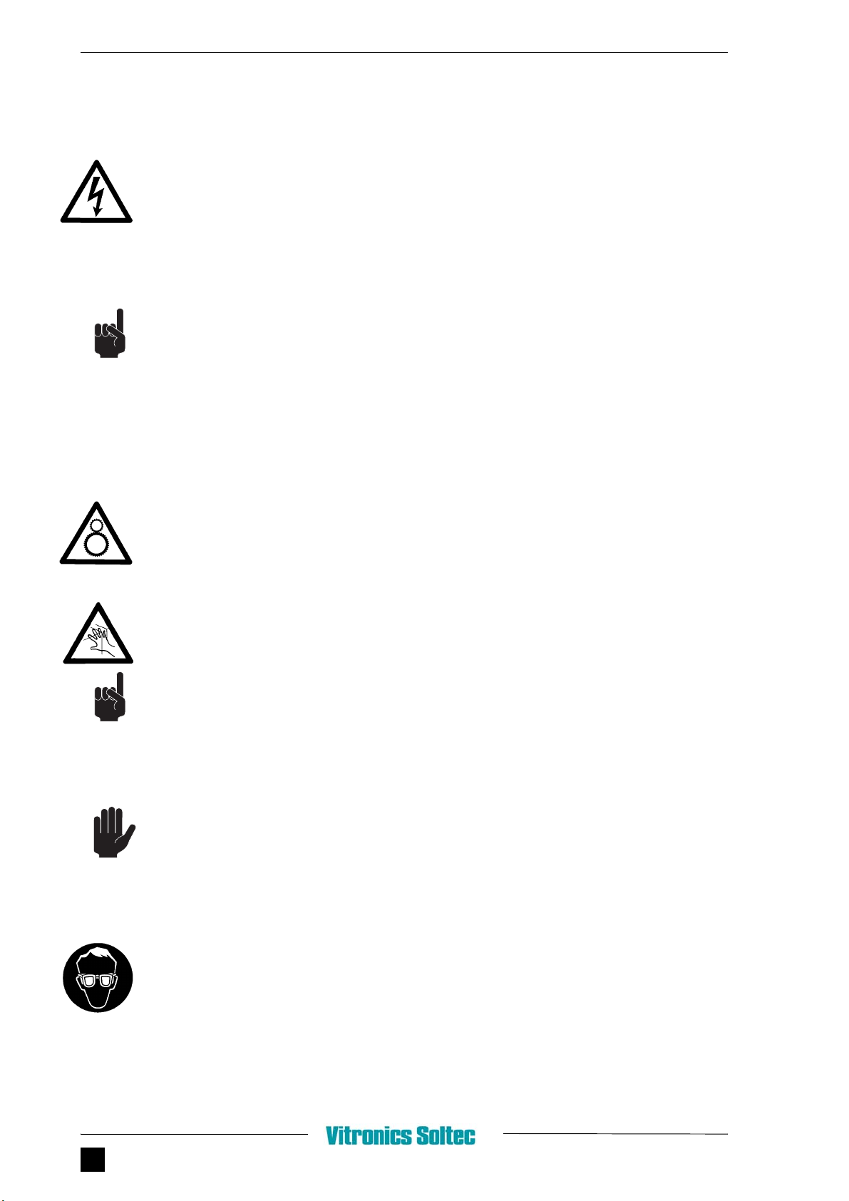
Symbols used in this manual.
WARNING. This symbol notices are used in this manual to emphasize dangerous conditions
that could cause personal injury.
CAUTION. Caution notices are used to call attention to a situation that could cause damage to
the machine.
NOTE. This symbol calls attention to information that is significant.
READ CAREFULLY AND FOLLOW THE WARNINGS AND CAUTIONS SHOWN
IN THIS CHAPTER.
1.3 REQUIRED MATERIALS TO WORK SAFE
We have made a kit including the required materials to work safe with your soldering equipment.
1.3.1 ORDERING DETAILS
This kit UG0200 can be ordered through your Vitronics Soltec office or local representative.
The kit includes:
The part numbers can also be ordered as separate items.
PART NUMBER QUANTITY DESCRIPTION
42284 5Hand gloves heat resistant size 10
42285 5Eye protection glass (ski type
42286 30 Mouth protection mask 3M9928
42287 20 Hand gloves rubber size 10
42288 2Apron size 80 x 100 cm
1.4 - HAZARDS
Installation Guide myReflow CHAPTER 1 3
1.4 HAZARDS
1.4.1 FLUX VAPOURS
The solderpaste used on the printed circuit boards mainly consists of tin, lead and flux.
Repeatedly inhaling this vapours can cause health problems in the long term.
When the board is heated, a noxious vapour will be liberated. This vapour must be extracted.
To avoid inhalation of this vapours, wear mouth protection when working on the machine.
• When large amounts of this vapours are inhaling or ingested, contact a physician immedi-
ately. Always follow the first aid procedures described in the Material Safety Data Sheet
from the flux.
• When small amounts are inhaled, seek fresh air.
• Be sure that the exhaust system works properly.
• Never eat, drink or smoke while working on the machine.
• Wash hands after handling flux.
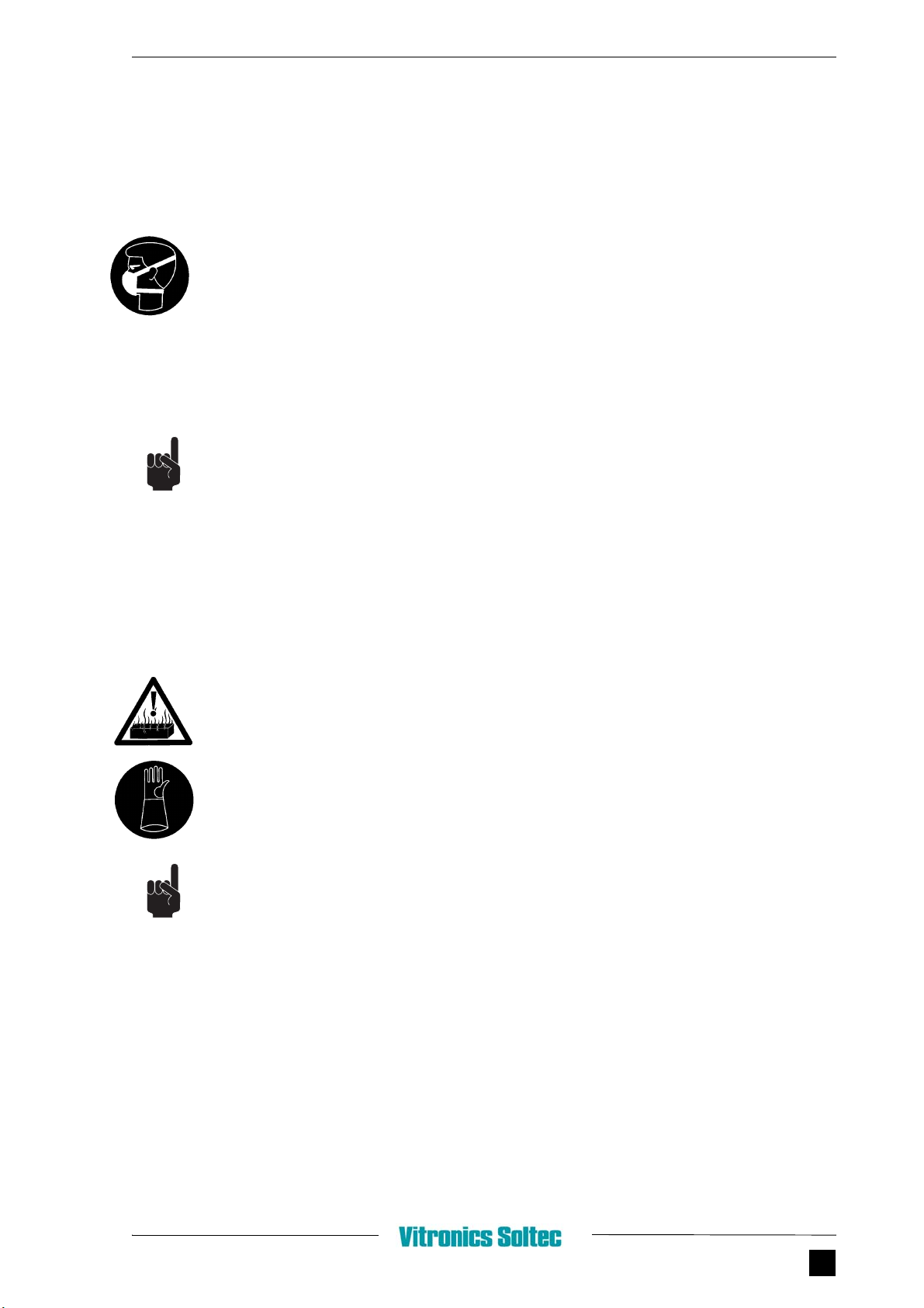
1.4.2 HOT SURFACES
There is always a risk of being burned when you work around the machine. Hot surfaces can
cause burns.
• Always wear heat resistant gloves and protective clothing when working on the machine.
• Never handle the finished boards without wearing protective gloves.
• If possible allow the machine time to cool down before you start servicing.
• When burned, immerse in cold water immediately. When the burn is severe consult a physi-
cian as soon as possible.
• Most of the components in the soldering system don’t look hot. Always assume that all parts
are hot.
SAFETY FEATURES
4CHAPTER 1
1.4.3 HIGH VOLTAGES
The 3 x 400 Volt supply present an electrical hazard.
High voltages are present on various parts of the system.
Hazard warning labels are places on the outside and inside of the enclosures.
• To avoid exposure to high voltages, ensure that the protective panels remain closed during
operation.
• Only qualified electricians should work on the electrical circuits of the machine.
• Before working on an electrical circuit, turn main power off and block the mainswitch with a
padlock.
• Ensure that the system is properly grounded.
1.4.4 MECHANICAL HAZARD
All moving parts of the soldering system, including pulleys, belts, chains, coolingfans, sprocket-
wheels and cylinders present a potential danger.
Be careful with covers and doors. Always pay attention to opening and closing.
• Take care not to get your hands or fingers in any moving mechanisms.
• Be mindful of long hair, neckties, bracelets and other parts that can get caught in a moving
mechanism.
• Always stop all moving parts when performing service on the machine.
ALWAYS PLACE AND CLOSE COVERS / WINDOWS BACK BEFORE
OPERATING.
1.4.5 EYE HAZARD
When working on the machine, always protect your eyes with safety glasses.
1.4 - HAZARDS
Installation Guide myReflow CHAPTER 1 5
1.4.6 NITROGEN
• Follow the safety precautions and procedures described in the Material Safety Data
Sheet from the nitrogen supplier.
1.4.7 FIRE HAZARD
The solderpaste used on the printed circuit board contains, when heated, an noxious vapour that
is inflammable.
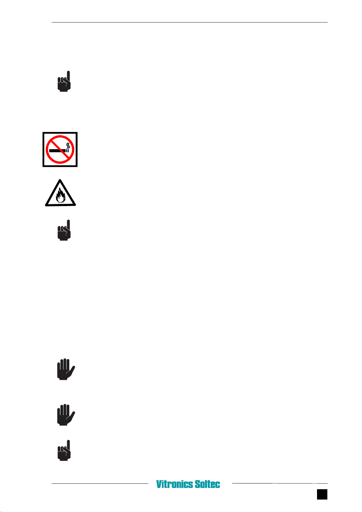
No smoking or open fire near the machine.
• The exhaust system to extract vapours should work fullproof.
• Be sure an fire-extinguisher is in the surroundings of the machine.
1.4.8 EXHAUST SYSTEM
Standard for testing purposes at Vitronics Soltec a bridge is made for “exhaust on”.
This bridge must be removed at Vitronics Soltec. Check if bridge is removed.
A Normally Open contact should be connected on this terminal connectors. When the exhaust
is switched on, the signal must be active after a short time (delay). This signal indicates that the
exhaust is working, and the machine can start up.
NEVER BRIDGE THIS INPUT. THIS CAN RESULT IN DAMAGING THE MACHINE.
DON’T USE THE MACHINE WITHOUT EXHAUST, THIS WILL DAMAGE THE
MACHINE.
TEST EVERY 6 MONTHS THE EXHAUST SYSTEM ON FUNCTIONING.

SAFETY FEATURES
6CHAPTER 1
1.5 PRECAUTIONS
•Always keep the working area clean.
•No smoking or open fire in the working area.
•NO-SMOKING signs should be posted in the work area (visible for everyone).
•Always wear protective clothing & glasses when working on the machine.
•Keep equipment well maintained.
•Be sure the working area is well ventilated.
•The machine must be installed with an effective ventilating system.
•Only qualified personnel is allowed to work on the equipment.
•Always keep fire extinguishers on hand.
•Fluids and rags used for cleaning must be collected and must be processed according to the
local environment rules.
•When finished working, remove overalls and other protective clothing.
•Wash thoroughly before eating, drinking or smoking.
•Never eat, drink or smoke around the machine.
•Only clean the machine when its cooled down.

1.6 - SAFETY
Installation Guide myReflow CHAPTER 1 7
1.6 SAFETY
1.6.1 AUDIBLE AND VISUAL INDICATIONS
The machine has both audible and visual signals: 1 buzzer and 3 signallights.
TABLE 1.1 BUZZER
T
ABLE 1.2 GREEN LIGHT
T
ABLE 1.3 YELLOW LIGHT
T
ABLE 1.4 RED LIGHT
SIGNAL FUNCTION
Fast Critical alarm. Machine will block
SIGNAL FUNCTION
Steady Machine run
Flashing slow Machine not at setpoint, machine stop
SIGNAL FUNCTION
Steady Overload (outfeed full). Machine will block
Flashing slow Alarm.
Flashing fast Critical alarm. Machine will block.
SIGNAL FUNCTION
Continuous E-stop active

SAFETY FEATURES
8CHAPTER 1
1.6.2 PRECAUTIONS
1.6.2.1 EMERGENCY SHUT DOWN
The standard machine is fitted with safety emergency switches. The emergency stop has a red
button (mushroom type) and a yellow shield.
The E-stop is a low voltage (24VDC) powered loop, that provides automatic shut-down of any
powered mechanism.
Indication that the E-stop is activated is given as an alarm message on the screen of the PC.
To restore normal working condition, release the E-stop button, and reset the E-stop in the PC
program.
1.6.2.2 CIRCUIT BREAKERS
The machine is foreseen with automatic circuit breakers and fuses in case of a short-circuit or
overload the circuit will be cut off.
Never use fuses or circuitbreakers in the machine which are not according the specifications from
the electrical circuit diagrams.
1.6.2.3 MAXIMUM CURRENT RELAYS
In case of an overcurrent in the motorcircuits, a relay protects the circuit and motors by switch-
ing off. Always be sure that the current setting is according to the electrical drawings and/or
adjustment procedures.
1.6.2.4 FREQUENCY INVERTER CONTROLLED MOTORS
Motors are controlled by the frequency inverter controllers.
In case of an overcurrent the relevant motor is stopped by the controller. An alarm is generated
on the PC screen. After solving the problem the alarm can be resetted and the motor can be
started again via the PC.
For more information see Schematics & Parts.
1.6.2.5 COVERS
The machine is foreseen with safety covers. This covers can be removed with a special key.
The main covers are provided with safety switches.

Installation manual myReflow CHAPTER 2 1
Installation 2
2.1 GENERAL
Installing only by trained Vitronics Soltec / Agent personnel.
At the end of this chapter an installation sheet is located.
2.2 TRANSPORT
2.2.1 SYMBOLS USED
FIGURE 2.1 SYMBOLS ON PACKAGING
1. Position pallet/box for transport
2. Breakable
3. Keep dry
4. Lift here (labels are placed on
position where forklift should lift)
12 4
3
VERSION 2009 November
INSTALLATION
2CHAPTER 2
2.3 UNPACKING
The Vitronics Soltec myReflow is packed on a wooden pallet. When necessary, the machine is
packed in crates (e.g. when shipped).
If packed in crates the following procedure (paragraph 2.3.1 and 2.3.2) should be followed.
When the machine is packed on a wooden pallet follow instructions in paragraph 2.3.2.
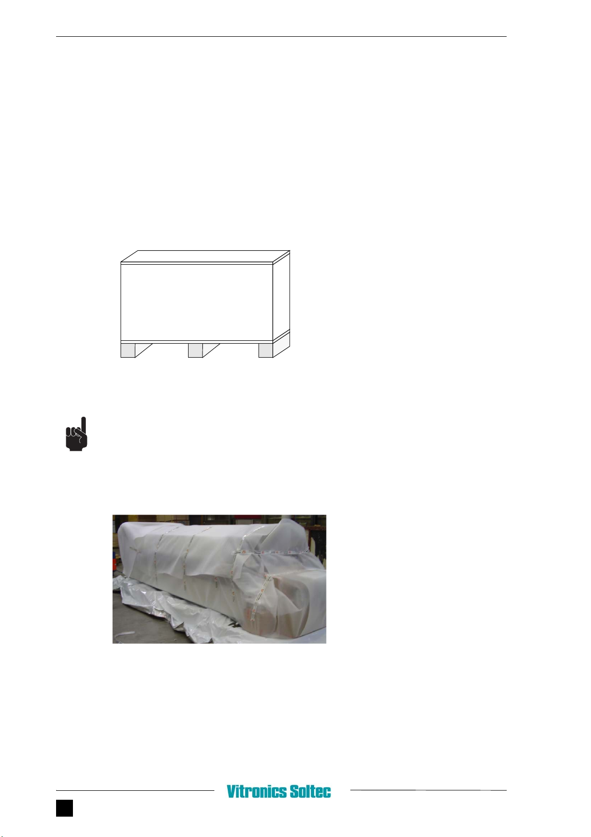
2.3.1 PACKET IN CRATE
FIGURE 2.2 CRATE
Use the above figure order A,B,C to uncrate. Other order can result in damaging the machine or
personal injury.
2.3.2 PACKED ON WOODEN PALLET
FIGURE 2.3 PACKING REMOVAL
CB
AUncrating order:
1. Take off top cover A.
2. Remove side panels B.
3. Remove front and backcover C.
1. Remove packing material
2.3 - UNPACKING
Installation manual myReflow CHAPTER 2 3
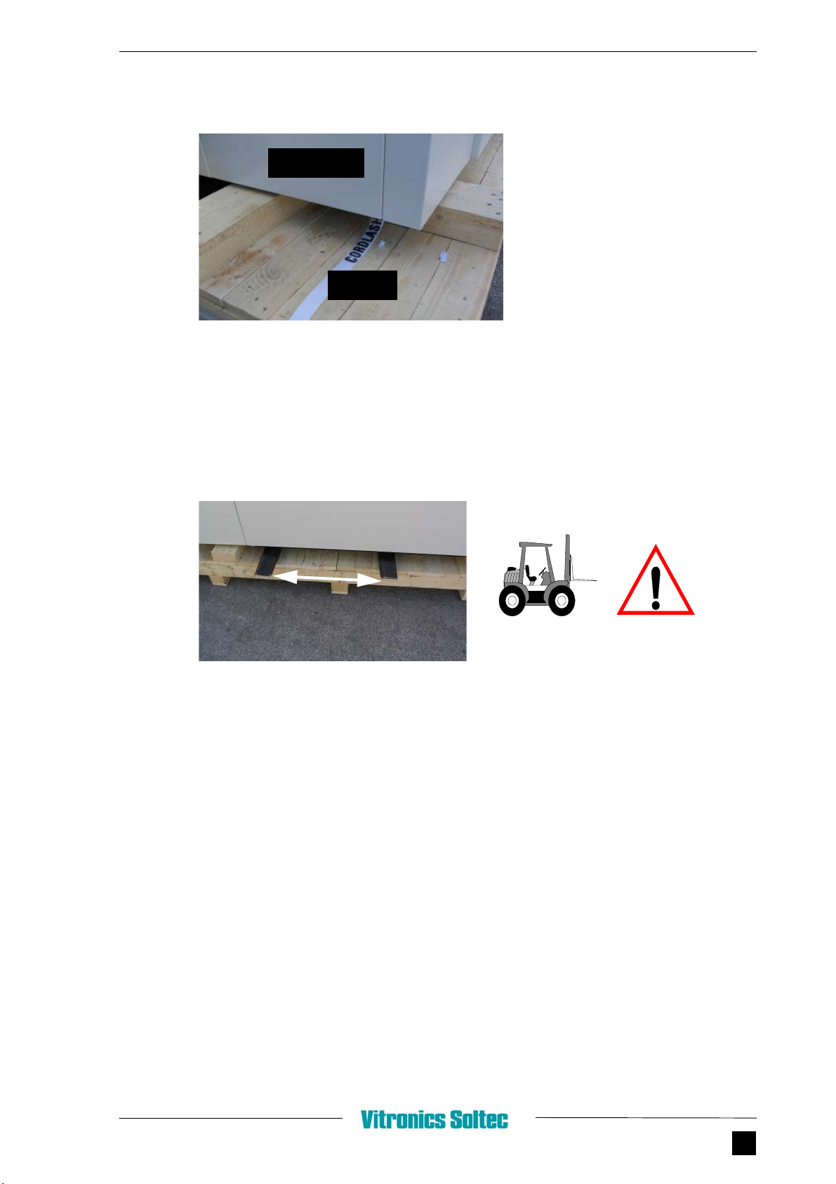
FIGURE 2.4 STRAPS REMOVAL
2.3.3 LIFTING WITH FORKLIFT
When the transporting straps are removed, the myReflow can be placed on the place the cus-
tomer has provided.
FIGURE 2.5 FORKLIFT UNDER MACHINE
To lift and transport the myReflow use the positions as shown in the installation sheet at the end
of this document.
2. Remove the coverdoors at the
strap-positions (total 4).
3. Remove straps
coverdoor
strap
* = DISTANCE BETWEEN FORKS minimum 1200mm
*

INSTALLATION
4CHAPTER 2
2.4 CONNECTIONS
2.4.1 GENERAL
See for connection specifications the “install sheet” at the end of this chapter.
2.4.2 ELECTRICAL CONNECTION
Only qualified electricians should work on the electrical circuits of the machine.
1. Connect the mains leads in accordance with the diagrams.
Check the Current rotation of the phases. The current rotation of the phases L1, L2, L3 must be
clockwise.
2. Block the mainswitch in the “OFF” position with a padlock to prevent dangerous situations.
2.4.3 NITROGEN CONNECTION
1. Connect the supply hose to the hose connector at the infeed side of the machine.
2.4.4 EXHAUST SYSTEM
One exhaust gauge of 165 mm (6.5”) is provided. This should be connected with the customer’s
exhaust system (not supplied by Vitronics Soltec).
• Inflammable and/or explosive gas might develop in the machine because of the evaporation of
the solvent in the flux.
• An exhaust system that functions well, will bring the gases below the explosion concentra-
tions.
• It is therefore necessary to have a sufficient exhaust in the machine.
• The exhaust system also has to be checked continuously on its well functioning.
• The machine is prepared to interfere in the E-stop circuit of the machine with a potential free
contact of the exhaust system. This contact has to be normally open, and therefore closed
when the exhaust functions well (fail safe).
NEVER USE THE MACHINE WITHOUT THE EXHAUST SYSTEM.
This manual suits for next models
5
Table of contents
Other Vitronics Soltec Soldering Gun manuals


