Weller HAP 200 User manual

HAP 200
Betriebsanleitung - Operating Instructions - Mode dèmploi - Istruzioni per lùso - Manual de uso -
Manual do utilizador - Gebruiksaanwijzing - Instruktionsbok - Betjeningsvejledning - Käyttöohjeet -
Οδηγίες Λειτουργίας- Kullanım kılavuzu - Návod k použití - Instrukcja obsługi - Üzemeltetési utasítás -
Návod na používanie - Navodila za uporabo - Kasutusjuhend - Lietosanas instrukcija -
Naudojimo instrukcija
005 57 050 00 / 03.2008
Replaces: 005 57 050 00 / 09.2007


HAP 200 – Operating Instructions I
The data specified above only serve to
describe the product. No statements
concerning a certain condition or suitability for
a certain application can be derived from our
information. The given information does not
release the user from the obligation of own
judgement and verification. It must be
remembered that our products are subject to a
natural process of wear and aging.
© This document, as well as the data,
specifications and other informations set forth
in it, are the exclusive property of Cooper
Tools GmbH. Without their consent it may not
be reproduced or given to third parties.
Subject to modifications.
Printed in Germany.
03.2008
Deutsch
DE
English
EN
Francais
FR
Italiano
IT
Español
ES
Português
PT
Nederlands
NL
Svenska
SV
Dansk
DK
Suomi
FI
Eλληvık
GR
Türkçe
TR
Česky
CZ
Polski
PL
Magyar
HU
Slovensky
SK
Slovenščina
SL
Saksa keel
EE
Lietuviškal
LV
Vāciski
LT

WR 3M II

EN FR IT ES PT NL SV DK FI GR TR CZ PL HU SK SL EE LV LT DE
HAP 200
Betriebsanleitung

HAP 200
HAP 200
Geräteübersicht
1 Elektrisches Anschlusskabel
mit Anschlussstecker
2 Anschluss Heißluftschlauch
3 Fingerschalter
4 Ablage
5 Düsenadapter
6 Düse
356
1
2
4

HAP 200 3-6
DE EN FR IT ES PT NL SV DK FI GR TR CZ PL HU SK SL EE LV LT
Inhalt
1Zu dieser Anleitung.................................................................... 3
2Zu Ihrer Sicherheit ..................................................................... 3
3Lieferumfang.............................................................................. 4
4Gerätebeschreibung .................................................................. 4
5Gerät in Betrieb nehmen............................................................ 5
6Zubehör ..................................................................................... 6
7Entsorgung ................................................................................ 6
8Garantie ..................................................................................... 6
1Zu dieser Anleitung
Wir danken Ihnen für das mit dem Kauf des Weller Heißluftkolbens
HAP 200 erwiesene Vertrauen. Bei der Fertigung wurden strengste
Qualitätsanforderungen zugrunde gelegt, die eine einwandfreie
Funktion des Gerätes sicherstellen.
Diese Anleitung enthält wichtige Informationen, um den HAP 200
sicher und sachgerecht in Betrieb zu nehmen, zu bedienen, zu
warten und einfache Störungen selbst zu beseitigen.
ZLesen Sie diese Anleitung und die beiliegenden
Sicherheitshinweise vor Inbetriebnahme des HAP 200 vollständig
durch, bevor Sie mit dem HAP 200 arbeiten.
ZBewahren Sie diese Anleitung so auf, dass sie für alle Benutzer
zugänglich ist.
1.1 Berücksichtigte Richtlinien
Der Weller Heißluftkolben HAP 200 entspricht den Angaben der
EG Konformitätserklärung mit den Richtlinien 89/336/EWG und
2006/95/EG.
1.2 Mitgeltende Dokumente
Betriebsanleitung des HAP 200
Begleitheft Sicherheitshinweise zu dieser Anleitung
Betriebsanleitung Ihres Steuergeräts
2Zu Ihrer Sicherheit
Der Heißluftkolben HAP 200 wurde entsprechend dem heutigen
Stand der Technik und den anerkannten sicherheitstechnischen
Regeln hergestellt. Trotzdem besteht die Gefahr von Personen- und
Sachschäden, wenn Sie die Sicherheitshinweise im beiliegenden
Sicherheitsheft sowie die Warnhinweise in dieser Anleitung nicht
beachten. Geben Sie den HAP 200 an Dritte stets zusammen mit
der Betriebsanleitung weiter.

4-6 HAP 200
2.1 Das müssen Sie beachten
Legen Sie den Heißluftkolben stets in der Originalablage ab.
Entfernen Sie alle brennbaren Gegenstände aus der Nähe des
heißen Lötwerkzeuges.
Schließen Sie niemals brennbare Gase an Ihre Heißluftgeräte an.
Tragen Sie geeignete Schutzkleidung beim Betrieb des HAP 200.
Richten Sie den Heißluftstrahl nicht auf Personen und schauen
Sie nicht in den Heißluftstrahl hinein.
Lassen Sie den heißen HAP 200 nie unbeaufsichtigt.
Arbeiten Sie nicht an unter Spannung stehenden Teilen.
Sorgen Sie bei der Verwendung von inerten Gasen für
ausreichende Belüftung.
Beachten Sie die Betriebsanleitung Ihres Steuergeräts.
2.2 Bestimmungsgemäßer Gebrauch
Verwenden Sie den HAP 200 ausschließlich gemäß dem in der
Betriebsanleitung angegebenen Zweck zum Löten und Entlöten von
oberflächenmontierten Bauelementen unter den hier angegebenen
Bedingungen. Der bestimmungsgemäße Gebrauch des HAP 200
schließt auch ein, dass
Sie diese Anleitung beachten,
Sie alle weiteren Begleitunterlagen beachten,
Sie die nationalen Unfallverhütungsvorschriften am Einsatzort
beachten.
Für andere von der Betriebsanleitung abweichende Verwendung,
sowie bei eigenmächtig vorgenommenen Veränderungen am Gerät
wird vom Hersteller keine Haftung übernommen.
3Lieferumfang
Heißluftkolben HAP 200, 005 27 116 99
Betriebsanleitung, 005 57 057 00
Heft Sicherheitshinweise
Ablage WDH 30, 005 15 152 99
Düse Ø 3,0 mm, 005 87 278 22
Steckschlüssel für Normaldüse, 005 87 488 62
Düsenadapter M6, 005 87 617 28
Gabelschlüssel SW8, 005 87 278 26
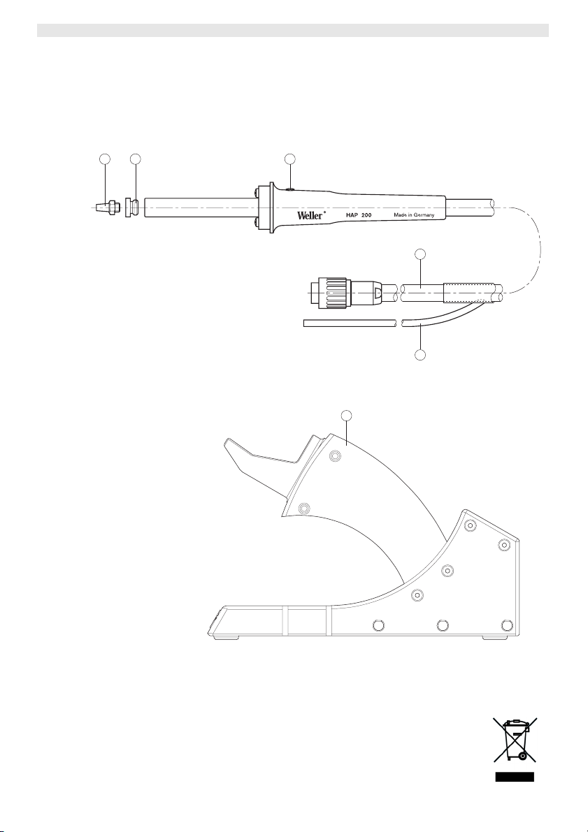
4Gerätebeschreibung
Die Weller Heißluftkolben HAP 200 mit integriertem Fingerschalter
(3) eignet sich zum Löten und Entlöten von oberflächenmontierten
Bauelementen. Ein breites Düsenprogramm macht ihn universell
einsetzbar.
Durch den im Handgriff integrierten Fingerschalter (3) wird der
Luftdurchfluss gesteuert. Die Ionenfalle im Kolben sorgt dafür, dass

HAP 200 5-6
DE EN FR IT ES PT NL SV DK FI GR TR CZ PL HU SK SL EE LV LT
die ausströmende Heißluft frei von statischen Ladungen ist.
Schlauch und Handgriff sind antistatisch ausgeführt.
Die temperaturgeregelte Heißluft kann mit dem Steuergerät
zwischen 50 °C und 550 °C eingestellt werden.
4.1 Technische Daten HAP 200
Heizleistung 200 W
Heizspannung 24 V AC
Max. Luftmenge 15 l/min
Temperaturbereich 50 °C bis 550 °C
Temperaturgenauigkeit 30 °C
Potentialausgleich
Der Heißluftkolben HAP 200 ist mit einer Potentialausgleichsleitung
ausgestattet, die gemäß der Betriebsanleitung des verwendeten
Steuergeräts beschaltet werden kann.
5Gerät in Betrieb nehmen
WARNUNG!
Verletzungsgefahr durch Heißluft und inerte Gase.
Beim Betrieb des Heißluftkolbens besteht Verbrennungsgefahr
durch austretende Heißluft. Bei Verwendung von inerten Gasen
besteht Erstickungsgefahr.
ZLesen Sie die beiliegenden Sicherheitshinweise, die
Sicherheitshinweise dieser Betriebsanleitung sowie die
Anleitung Ihres Steuergeräts vor in Betriebnahme des
HAP 200 vollständig durch und beachten Sie die darin
gegebenen Vorsichtsmaßnahmen
1. Den Heißluftkolben HAP 200 sorgfältig auspacken.
2. Sicherstellen, dass das Steuergerät ausgeschaltet ist.
3. Den Heißluftkolben HAP 200 in der Sicherheitsablage (4)
ablegen.
4. Den elektrischen Anschlussstecker (1) des HAP 200 in die
7-polige Anschlussbuchse des Steuergeräts einstecken und
durch kurze Rechtsdrehung verriegeln.
5. Die Schlauchleitung des HAP 200 (2) auf den „Air- Nippel“ des
Steuergeräts schieben.
6. Steuergerät am Netzschalter einschalten und Temperatur und
Luftdurchflussmenge einstellen.
Beachten Sie hierbei die Betriebsanleitung Ihres Steuergeräts.

6-6 HAP 200
5.1 Arbeitshinweise
VORSICHT!
Beschädigung des Kolbenheizkörpers durch zu
langes Düsengewinde.
Die Gewindetiefe für Heißluftdüsen beträgt max. 5 mm (0,2 "). Ein
längeres Gewinde führt zur Zerstörung des Heizkörpers.
ZAchten Sie auf die richtige Gewindetiefe der
einzuschraubenden Düsen!
ZVerwenden Sie Weller Originalheißluftdüsen!
Mit dem HAP 200 erhalten Sie einen SW8 Steckschlüssel.
Verwenden Sie diesen zum Düsenwechsel und kontern Sie am
Heizkörper mit dem mitgelieferten Gabelschlüssel.
Hinweis Wenn Sie den beiliegenden Düsenadapter (5) (005 87 610 28) mit
Hilfe des Steckschlüssels SW8 in den HAP 200 einschrauben,
können Sie die gleichen Düsen wie für den HAP 1 verwenden.
Ersatzheißluftkolben sind justiert und können ohne Nachjustierung
angeschlossen und verwendet werden.
Zur Überprüfung der Heißlufttemperatur wird die Verwendung einer
speziellen Messdüse (005 87 278 08) empfohlen, durch die ein
Mantelthermoelement (Ø 0,5 mm) kontaktiert werden kann.
6Zubehör
HAP 200 Heißluftdüsen (siehe Übersicht Hot Air Nozzles).
7Entsorgung
Entsorgen Sie ausgetauschte Geräteteile, Filter oder alte Geräte
gemäß den Vorschriften Ihres Landes.
8Garantie
Die Mängelansprüche des Käufers verjähren in einem Jahr ab
Ablieferung an ihn. Dies gilt nicht für Rückgriffsansprüche des
Käufers nach §§ 478, 479 BGB.
Aus einer von uns abgegebenen Garantie haften wir nur, wenn die
Beschaffenheits- oder Haltbarkeitsgarantie von uns schriftlich und
unter Verwendung des Begriffs „Garantie“ abgegeben worden ist.

EN
FR IT ES PT NL SV DK FI GR TR CZ PL HU SK SL EE LV LT DE
HAP 200
Operating Instruction

HAP 200
HAP 200
Device overview
1 Electrical connecting cable
with connector
2 Hot air hose connection
3 Finger switch
4 Stand
5 Nozzle adaptor
6 Nozzle
356
1
2
4

HAP 200 3-6
DE EN FR IT ES PT NL SV DK FI GR TR CZ PL HU SK SL EE LV LT
Contents
1About these instructions ............................................................ 3
2For your safety........................................................................... 3
3Scope of supply ......................................................................... 4
4Device description ..................................................................... 4
5Starting up the device................................................................ 5
6Accessories ............................................................................... 6
7Disposal..................................................................................... 6
8Warranty .................................................................................... 6
1 About these instructions
Thank you for the confidence you have shown in buying the HAP
200 Hot Air Tool. The device has been manufactured in accordance
with the most rigorous quality standards, which ensure that the
device operates perfectly.
These instructions contain important information which will help you
to start up, operate and service the HAP 200 safely and correctly as
well as to eliminate simple faults/malfunctions yourselves.
ZPlease read carefully these instructions and the attached safety
guidelines before you put the HAP 200 into operation.
ZKeep these instructions in a place that is accessible to all users.
1.1 Directives taken into consideration
The Weller HAP 200 Hot Air Tool conforms to the specifications of
the EC Declaration of Conformity with Directives 89/336/EEC and
2006/95/EC.
1.2 Documents also applicable
HAP 200 Operating Instructions
Accompanying booklet on safety
Operating instructions of your control unit
2For your safety
The HAP 200 Hot Air Tool has been manufactured in accordance
with state-of-the-art technology and recognised safety rules and
regulations. There is nevertheless the risk of personal injury and
damage to property if you fail to observe the safety information set
out in the enclosed booklet accompanying these operating
instructions and the warnings given herein. Always pass on the HAP
200 to third parties together with these operating instructions.

4-6 HAP 200
2.1 Please observe the following:
Always place the Hot Air Tool in its original stand.
Remove all flammable objects from the vicinity of the hot soldering
tool.
Do not connect flammable gases to your hot air equipment.
Always wear suitable protective clothing when using the HAP 200.
Do not direct the hot air jet at persons or look into the hot air jet.
Never leave the hot HAP 200 unattended.
Do not carry out work on live parts.
When using inert gases, make sure the area is well ventilated.
Read and observe the operating instructions of your control unit.
2.2 Intended use
Use the HAP 200 exclusively for the purpose indicated in the
operating instructions of releasing, accommodating and setting down
chip components under the conditions specified here. Intended use
of the HAP 200 also includes the requirement that
you read and follow these instructions,
you read and follow all additional accompanying documents,
observe the national accident-prevention regulations applicable at
the location where the device is being used.
The manufacturer accepts no liability for damages resulting from
failure to use the device in compliance with these operating
instructions or unauthorised modifications to the device.
3Scope of supply
Hot Air Tool HAP 200, 005 27 116 99
Operating Instructions, 005 57 057 00
Safety booklet
Stand WDH 30, 005 15 152 99
Nozzle Ø 3.0 mm, 005 87 278 22
Socket wrench for standard nozzle, 005 87 488 62
Nozzle adaptor M6, 005 87 617 28
Open-end wrench 8 mm across flats, 005 87 278 26
4Device description
The Weller HAP 200 Hot Air Tool with integrated finger switch (3) is
suitable for soldering and desoldering surface-mounted components.
A wide range of nozzles makes the HAP 200 a real general-purpose
tool.
A finger switch (3) integrated in the handle is used to control the air
flow. The ionising circuit integrated in the tool ensures that hot air is
static free. The hose and handle are of antistatic design.
The hot air temperature can be set to between 50 °C and 550 °C
using the control unit.

HAP 200 5-6
DE EN FR IT ES PT NL SV DK FI GR TR CZ PL HU SK SL EE LV LT
4.1 Technical data HAP 200
Heating output 200 W
Heating voltage 24 V AC
Max. air flow rate 15 l/min
Temperature range 50 °C up to 550 °C
Temperature accuracy 30 °C
Potential balance
The HAP 200 Hot Air Tool has an equipotential bonding conductor
which can be connected in accordance with the operating
instructions of the control unit in use.
5Starting up the device
WARNING!
Risk of injury due to hot air and inert gases.
Use caution when operating the Hot Air Tool, because hot air can
cause burns. Caution: use of inert gases in an enclosed area can
cause asphyxiation.
ZPlease read carefully the safety instructions in the attached
booklet, the safety guidelines given in these operating
instructions and the operating instructions of your control unit
before putting the HAP 200 into operation. Also observe the
safety precautions described herein.
1. Carefully unpack Hot Air Tool HAP 200.
2. Make sure that the control unit is OFF.
3. Place the HAP 200 Hot Air Tool into the stand (4).
4. Insert the electrical connector (1) of the HAP 200 into the 7-pin
terminal jack on the control unit, and lock in place by briefly
twisting clockwise.
5. Push the air hose of the HAP 200 (2) onto the “Air” nipple on the
control unit.
6. Turn on the control unit at the power switch and set the
temperature and air flow.
Also read and observe the operating instructions of your control
unit.

6-6 HAP 200
5.1 Operating guidelines
Caution!
Excessively long nozzle threads can damage the
heater core of your tool.
The max. thread depth for hot air nozzles is 5 mm (0.2 "). Use of
longer threads will cause irreparable damage to the heater core.
ZPay attention to the correct thread depth of the screw-in
nozzles!
ZAlways use Weller original hot air nozzles!
The HAP 200 is supplied with an 8 mm socket wrench. Use this to
replace the nozzles. Lock the nuts on the heater core using the
supplied open-end wrench.
Note If you screw the enclosed nozzle adaptor (5) (005 87 610 28) into
the HAP 200 using the 8 mm socket wrench, you can use the same
nozzles as for the HAP 1.
Replacement Hot Air Tools are supplied preset and can be
connected up and used without any need for readjustment.
To check the hot air temperature, it is recommended that you use a
special test nozzle (005 87 278 08) which mates with a sheathed
thermocouple (Ø 0.5 mm).
6Accessories
HAP 200 hot air nozzles (see overview Hot Air Nozzles)
7Disposal
Dispose of replaced equipment parts, filters or old devices in
accordance with the rules and regulations applicable in your country.
8Warranty
Claims by the buyer for physical defects are time-barred after a
period of one year from delivery to the buyer. This does not apply to
claims by the buyer for indemnification in accordance with
§§ 478, 479 BGB (German Federal Law Gazette).
We shall only be liable arising from a warranty furnished by us if the
quality or durability warranty has been furnished by use in writing
and using the term "Warranty“.

EN
FR
IT ES PT NL SV DK FI GR TR CZ PL HU SK SL EE LV LT DE
HAP 200
Mode d’emploi

HAP 200
HAP 200
Aperçu de l'appareil
1 Câble de raccordement
électrique avec connecteur
2 Raccord flexible d'air chaud
3 Interrupteur digital
4 Support
5 Adaptateur de buse
6 Buse
356
1
2
4

HAP 200 3-6
DE EN FR IT ES PT NL SV DK FI GR TR CZ PL HU SK SL EE LV LT
Sommaire
1A propos de ce manuel.............................................................. 3
2Pour votre sécurité..................................................................... 3
3Ensemble de la livraison............................................................ 4
4Description de l'appareil ............................................................ 4
5Mise en service de l'appareil ..................................................... 5
6Accessoires ............................................................................... 6
7Mise au rebut ............................................................................. 6
8Garantie ..................................................................................... 6
1 A propos de ce manuel
Nous vous remercions de la confiance que vous nous témoignée
avec l'achat du fer à air chaud HAP 200. Les exigences les plus
sévères en matière de qualité ont accompagné la fabrication et
garantissent un fonctionnement impeccable de l'appareil.
Ce manuel contient des informations importantes pour mettre en
service, utiliser et entretenir le HAP 200 en toute sécurité et en
bonne et due forme ainsi que pour éliminer les dérangements
simples.
ZLisez entièrement ce manuel et les consignes de sécurité qui y
sont jointes avant de mettre en service le HAP 200 et de travailler
avec.
ZConservez ce manuel de sorte à ce qu'il soit accessible à tous
les utilisateurs.
1.1 Directives prises en compte
Le fer à air chaud HAP 200 de Weller est conforme aux indications
de la déclaration de conformité CE avec les directives 89/336/CEE
et 2006/95/CE.
1.2 Documents applicables
Manuel d'utilisation du HAP 200
Livret sur les consignes de sécurité accompagnant le manuel
Manuel d'utilisation de votre appareil de commande
2Pour votre sécurité
Le fer à air chaud HAP 200 a été fabriqué conformément au niveau
actuel de la technique et aux règles de sécurité techniques
reconnues. Il subsiste malgré tout un risque de blessures corporelles
et de dommages matériels si vous n'observez pas les consignes de
sécurité figurant dans le livret qui accompagne l'appareil de
commande ainsi que les avertissements de ce manuel. Remettez
toujours le HAP 200 à un tiers, accompagné du manuel d'utilisation.

4-6 HAP 200
2.1 Les consignes à respecter
Replacez toujours le fer à air chaud sur son support original.
Eloignez tous les objets inflammables de la proximité de l'outil de
soudage chaud.
Ne raccordez jamais des gaz inflammables à vos appareils à air
chaud.
Portez des vêtements de protection adéquats lorsque vous utilisez
le HAP 200.
Ne dirigez pas le jet d'air chaud sur des personnes et ne dirigez
pas vos regards à l'intérieur.
Ne laissez jamais le HAP 200 sans surveillance.
Ne pas effectuer d'intervention sur des pièces sous tension.
En cas d'utilisation de gaz inertes, veillez à une aération
suffisante.
Respectez le manuel d'utilisation de votre appareil de commande.
2.2 Utilisation conforme aux prescriptions
Utilisez uniquement le HAP 200 selon l'usage prévu mentionné dans
ce manuel, à savoir pour le soudage et le dessoudage d'éléments
montés en surface dans les conditions indiquées. L'utilisation
conforme du HAP 200 inclut également le respect des consignes
de ce manuel,
de tous les autres documents d'accompagnement,
des prescriptions nationales sur site en matière de prévention des
accidents.
Pour une utilisation autre que celle mentionnée dans ce manuel
d'utilisation ainsi qu'en cas de modifications effectuées de votre
propre chef sur l'appareil, la responsabilité du fabricant n'est pas
engagée.
3Ensemble de la livraison
Fer à air chaud HAP 200, 005 27 116 99
Manuel d'utilisation, 005 57 057 00
Livret des consignes de sécurité
Support WDH 30, 005 15 152 99
Buse Ø 3,0 mm, 005 87 278 22
Clé à douille pour buse normale, 005 87 488 62
Adaptateur de buse M6, 005 87 617 28
Clé à fourche ouverture 8, 005 87 278 26
4Description de l'appareil
Le fer à air chaud HAP 200 de Weller avec interrupteur digital
intégré (3) est destiné au soudage et au dessoudage d'éléments
montés en surface. Une gamme étendue de buses rend son usage
universel.
Other manuals for HAP 200
1
Table of contents
Languages:
Other Weller Soldering Gun manuals

Weller
Weller WTQB 1000 User manual

Weller
Weller WSF 80 User manual

Weller
Weller WMD 3 User manual

Weller
Weller WS 50 User manual

Weller
Weller WDD 81V User manual

Weller
Weller WSM 1 User manual

Weller
Weller WXP?65 User manual

Weller
Weller BP860MP User manual

Weller
Weller WXP 120 User manual

Weller
Weller MPR 90 User manual

Weller
Weller WAD 101 User manual

Weller
Weller WSD 151 User manual

Weller
Weller wsd 161 User manual

Weller
Weller PYROPEN Piezo User manual

Weller
Weller whs 40d User manual

Weller
Weller SI 120 User manual

Weller
Weller WXsmart User manual

Weller
Weller wsd 80 User manual

Weller
Weller WDD 161V User manual

Weller
Weller PUD 81R User manual