jbc BT-2BQA User manual

BT-2BQA
Soldering Station
INSTRUCTION MANUAL
INSTRUCTION MANUAL

Packing List
The following items are included:
Power Cord ................................................ 1 unit
Ref. 0023714 (230V)
Manual ........................................................................................................................................................ 1 unit
Ref. 0030004
Control Unit ............................................... 1 unit
Brass Wool ................................................. 1 unit
Ref. CL6210
General Purpose Handle ..................... 1 unit
Ref. T245-A
Soldering Station
Ref. BT1B010
www.jbctools.com
This manual corresponds to the following references:
BT-2BQA - 230V
2

Features Cable collector
Quick Tip Changer
Tip
Cleaning
System
Stand
Yellow LED
(SLEEP)
Green LED
(IN USE)
Dial
Main switch
Fuse
Power Socket Equipotential connection
T245
General Purpose Handle
3
40 mm
50 mm
60 mm
80 mm
100 mm
130 mm 130 mm
para manuales - color gris
200 mm
300 mm

CD-Q:
OK
CD-Q:
OK
CD-Q:
OK
Changing Grips*
Hold the grip and pull the tab.
Use pliers if necessary.
Tabs
New Grip
Replace the soft foam grips easily using the slip-on tabs. Note: Choose the correct grip depending on
your handle model.
1. Inserting Tabs 2. Inserting Handle 3. Removing Tabs
The sealing plug prevents undesirable flux vapors or particles from entering inside the tool. Its usage
is highly recommended for intensive applications when soldering is exposed to FOD environments or
for applications where the soldering iron works close to vertical position.
Replacing Sealing Plugs
Note: Choose the correct sealing plug depending on your
handle model.
Before replacing the sealing plug, unplug the power
supply and make sure the device is not hot.
Note: The chamfered side has
to be positioned towards the
handle.
2. Mounting Position 3. Inserting Sealing Plug1. Removing Sealing Plug
Sealing
Plug
Handle
Push the sealing plug inside
the handle until the sealing
plug and handle edges are
aligned.
Enter, not deeper than 8mm,
a small shaft or screwdriver,
lift and pull the sealing plug.
Never use a cartridge to do
this operation.
Push the grip with the tabs
onto the handle.
Handles Green grips Blue grips Black grips
T210, T210P, T210N T8658 T3310 T3311
T245, T245G, T245P T6057 T1528 T1530
Handles Sealing Plug
T210 OB1000
T245, T470 OB2000
* not included, sold separately
Put the slide-on tabs into the
new grip.
4

Quick Tip Changer
Compatible cartridges
The BT stations work with C245 cartridges and T245/T470 handpieces or C210 cartridges with T210
handpieces. Find the model that best suits your soldering needs in www.jbctools.com
Save time and change cartridges safely without switching the station off.
1. Removing 2. Inserting 3. Fixing
Place the handpiece in the
extractor and pull to
remove the cartridge.
Place the handpiece on top
of the new cartridge and
press down slightly.
Use the holes for fixing the
cartridge* as follows:
A. For straight C210.
B. For curved C210.
C. For C245.
*Important
It is essential to insert the cartridges as far as the mark for a proper connection.
Mark
B
C
A
5
40 mm
50 mm
60 mm
80 mm
100 mm
130 mm 130 mm
para manuales - color gris
200 mm
300 mm

Operation
AC Console
The LEDs indicate the station’s different work-
ing modes.
1. Station without a tool connected: The
green IN USE light flashes with the sequence
(- - -- --).
2. Tool out of the support: The green IN
USE light is permanently lit, indicating that the
soldering iron tip is at working temperature.
3. Tool in the support (sleep mode): The yel-
low SLEEP light is permanently lit. In order that
the tool goes into sleep mode, the tool must
be in its support and the programmed sleep
temperature must be less than the temp. on the
dial or the prefixed temperature.
4. Station with previously fixed temperature.
(Only for users of the AC console).
Soldering iron out of support:
- If the dial is above the prefixed temperature,
the green IN USE light is lit the majority of the
time, switching off briefly at regular intervals
(___ ___).
- If the dial is below the prefixed temperature,
the green IN USE light is off the majority of
the time, lighting up briefly at regular intervals
(- - -).
- If the dial is at the prefixed temperature, the
green light is permanently lit.
Errors
When the handpiece or the cartridge is in an
open circuit, the green IN USE light flashes with
the sequence (- - - - - -).
When the handpiece or the cartridge is in a
short circuit, the green IN USE light flashes with
the sequence (--- --- ---).
If any of the above mentioned causes is corrected,
the station will start working automatically.
If the station is used continually in a overloaded
condition for a period of time, the system will
stop and both leds will flash simultaniusly.
Switch station off and on to reset and review
the soldering application.
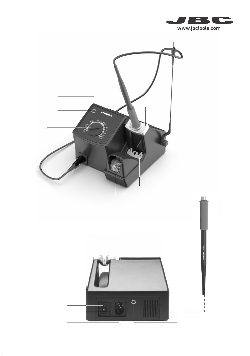
Yellow LED
(SLEEP)
Green LED (IN USE)
Dial
The original parameters of control unit can be
modified using the AC console.
It is necessary to connect the console AC with
software revision 7.0 or later to the BT in order to
configure it (consult JBC for console software updates).
Previous versions only allow for reading of
counters and do not allow for modification of
parameters.
Configuration possible:
- Fixing the working temperature.
- Selection of temperature units ºC or ºF.
- Modification of sleep temperatures and standby
times.
- Adjustment of temperature.
- Reset the parameters back to factory settings.
- Read-out data:
- Working hours.
- Sleep cycles and sleep hours.
- Cartridge and iron changes.
- Program version.
6

Before carrying out maintenance, always allow the equipment to cool.
Clean
periodically
- Clean the station screen with a glass cleaner
or a damp cloth.
- Use a damp cloth to clean the casing and the
tool. Alcohol can only be used to clean the
metal parts.
- Periodically check that the metal parts of the
tool and stand are clean so that the station
can detect the tool status.
- Maintain tip surface clean and tinned prior to
storage in order to avoid tip oxidation.
Rusty and dirty surfaces reduce heat transfer
to the solder joint.
- Periodically check all cables and tubes.
- Replace a blown fuse as follows:
Maintenance
1. Pull off the fuse holder and remove the
fuse. If necessary use a tool to lever it off.
2. Press the new fuse into the fuse holder
and replace it in the station.
- Replace any defective or damaged pieces. Use original JBC spare parts only.
- Repairs should only be performed by a JBC authorized technical service.
7
40 mm
50 mm
60 mm
80 mm
100 mm
130 mm 130 mm
para manuales - color gris
200 mm
300 mm

- Do not use the units for any purpose other than soldering or rework. Incorrect use may cause fire.
- The power cord must be plugged into approved bases. Be sure that it is properly grounded before
use. When unplugging it, hold the plug, not the wire.
- Do not work on electrically live parts.
- The tool should be placed in the stand when not in use in order to activate the sleep mode.
The soldering tip, the metal part of the tool and the stand may still be hot even when the station is
turned off. Handle with care, including when adjusting the stand position.
- Do not leave the appliance unattended when it is on.
- Do not cover the ventilation grills. Heat can cause inflamable products to ignite.
- Use a “non residue” classified flux and avoid contact with skin or eyes to prevent irritation.
- Be careful with the fumes produced when soldering.
- Keep your workplace clean and tidy. Wear appropriate protection glasses and gloves when
working to avoid personal harm.
- Utmost care must be taken with liquid tin waste which can cause burns.
- This appliance can be used by children over the age of eight and also persons with reduced
physical, sensory or mental capabilities or lack of experience provided that they have been given
adequate supervision or instruction concerning use of the appliance and understand the hazards
involved. Children must not play with the appliance.
- Maintenance must not be carried out by children unless supervised.
Safety
It is imperative to follow safety guidelines to prevent electric
shock, injury, fire or explosion.
8

Notes
9
40 mm
50 mm
60 mm
80 mm
100 mm
130 mm 130 mm
para manuales - color gris
200 mm
300 mm

Notes
10

BT-2BQA
Soldering Station
Ref. BT-2BQA 230V 50/60Hz. Input fuse: 1A. Output: 24V
- Power: 75W
- Temperature range: 100-450°C (200-850 ºF) (±5%)
- Total Net Weight: 2.67 Kg / 5.87 lb
- Package Dimensions/Weight: 213 x 220 x 160 mm / 2.96 kg
(L x W x H) 8.39 x 8.66 x 6.30 in / 6.53 lb
Complies with CE standards
ESD safe
Specifications
11
40 mm
50 mm
60 mm
80 mm
100 mm
130 mm 130 mm
para manuales - color gris
200 mm
300 mm

This product should not be thrown in the garbage.
In accordance with the European directive 2012/19/EU, electronic equipment at the end of its life must
be collected and returned to an authorized recycling facility.
Warranty
JBC’s 2 year warranty covers this equipment against
all manufacturing defects, including the replacement
of defective parts and labour.
Warranty does not cover product wear or misuse.
In order for the warranty to be valid, equipment must
be returned, postage paid, to the dealer where it was
purchased.
Get 1 extra year JBC warranty by registering here:
https://www.jbctools.com/productregistration/
within 30 days of purchase.
40 mm
50 mm
60 mm
80 mm
100 mm
130 mm 130 mm
para manuales - color gris
200 mm
300 mm
0030004-090922
Table of contents
Other jbc Soldering Gun manuals