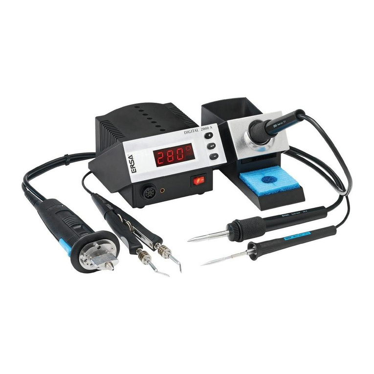
ersa DIGITAL 2000 A User manual

Инструкция по эксплуатации • Operating instructions
ERSA DIGITAL 2000 A

2
Содержание
1. Введение
2. Технические данные
3. Правила безопасности
4. Ввод в эксплуатацию
5. Функциональное описание
6. Диагностика
неисправностей
7. Уход за станцией
8. Элементы и номенклатурные
номера
9. Гарантийные обязательства
1. Introduction
2. Technical Data
3. Safety information
4. Starting operation
5. Functional description
6. Error diagnosis and
Troubleshooting
7. Maintenance and Servicing
8. Replacement parts and
ordering information
9. Warranty
Contents1.

3
DIGITAL 2000
8. Контейнер для губки
9. Вискозная губка для чистки жал
10. Выключатель питания
11. Гнездо заземления
12. Разъем для подключения инструмента
13. Шнур инструмента
14. Гнездо предохранителя
15. Шнур питания
16. Разъем питания
1. Display
2. Supply unit
3. Control buttons
4. Holder
5. Tip magazine
6. Soldering tool
7. Soldering tip
8. Sponge bin
9. Viscose sponge
10. Power switch
11. Potential equalization jack
12. Soldering iron plug
13. Soldering iron connecting cable
14. Fuse / fuse holder
15. Power cord
16. Power plug
1. Дисплей
2. Блок питания и управления
3. Кнопки управления
4. Подставка-держатель паяльника
5. Обойма для пайльных жал и
насадок для выпаивания
6. Паяльник
7. Паяльное жало
1 2 3 4 5
13 12 11
10 9 8 7 6 14 15
16
рис. 1 / fig. 1
DIGITAL 2000 A

4
Введение Introduction
DIGITAL 2000A – полностью антистатическая
паяльная станция с микропроцессорным
управлением, разработанная немецкой
фирмой ERSA для производственных
применений, ремонтных мастерских и
лабораторий
1.1 Управляющий блок
Паяльной станцией особенно удобно
пользоваться благодаря применению
микропроцессора: используя возможности
меню, можно вводить и сохранять значения
установок независимо для четырех
инструментов.
Унифицированный управляющий
блок станции DIGITAL 2000A может
работать попеременно c мощным
паяльником PowerTool, универсальным
высокоскоростным паяльником TechTool,
микропаяльником MicroTool, термопинцетом
ChipTool и вакуумным термоотсосом X-Tool.
Благодаря высокой точности и скорости
выполнения работ, эта паяльная станция
идеально подходит для производств с
высокими требованиями к качеству
We appreciate your decision to purchase this
high-quality soldering station. The DIGITAL 2000
A from ERSA is a top-of-the-line micro-proces-
sor-controlled soldering station. It is designed
for use in industrial production, repairs and in
laboratories.
1.1 Supply Unit
The use of a microprocessor facilitates operation
and sets new standards for the functions avail-
able at the soldering station. Five independent
tool settings can be made and saved by means
of a simple menu guide.
The DIGITAL 2000 A can be operated with vari-
ous soldering tools. Besides the universal solder-
ing irons, Power tool and Tech tool, the fine-pitch
soldering iron Micro tool and the Chip tool can be
connected to the station for processing SMCs.
The optionally connectable X-tool desoldering
iron rounds off our range of tools. The solder-
ing station can be used for simple temperature
measurements when a temperature sensor is
connected as tool (Pr5).
A wide variety of functions, high speed and
control precision make this soldering station
especially suitable for manufacturing processes
subject to stringent quality requirements.
1.
5
Введение Introduction
Электрические характеристики:
• Полное антистатическое исполнение
• Гальваническая развязка от питающей сети
• Безопасное заземление инструмента
• Вторичное напряжение переменного тока 24В
• Соответствие стандартам VDE-GS, CE,VDE-
EMC
Equipment features:
• Antistatic design
• Potential equalisation
• Full-wave control
• 24 V small voltage for soldering irons
• VDE-GS, CE, VDE-EMC marks of conformity
1.
MicroTool
Паяльник MicroTool предназначен
для использования преимущественно
с компонентами, монтируемыми на
поверхность (SMD). Его малый размер и
тонкие жала идеально подходят для самых
изящных работ.
Micro tool
This soldering tool is designed primarily for SMT
components. The slender form and fine-pitch
tips make the tool especially suitable for preci-
sion work.
1.2 Soldering and Desoldering
Tools
Tech tool
The Tech tool is a heavy-duty, universally appli-
cable tool for performing most soldering tasks.
Its applications range from especially fine-pitch
soldering (SMD technology) to soldering with
major heat requirements (cables, connec-
tors, switches, etc.). The soldering tips can be
exchanged even when hot, without the assist-
ance of other tools.
1.2 Инструменты для пайки
и выпаивания
TechTool
Паяльник TechTool –
высокопроизводительный универсальный
паяльник, который может быть использован
для большинства работ. Диапазон
применений простирается от микропайки
(технология SMD) до пайки, требующей
довольно большой мощности (кабель,
разъемы, переключатели и т.д.). Смена жала
паяльника даже в горячем состоянии не
требует специального инструмента.

6
Введение Introduction
ChipTool
Термопинцет ChipTool со сменными
насадками предназначен для выпаивания
SMD компонентов широкого диапазона от
чипов 0201 до микросхем PLCC84.
Chip tool
The Chip tool is designed for desoldering SMT
components. ERSA provides an extensive range
of tips for this tool, for desoldering all current
components from 0201 to PLCC 84.
1.
PowerTool
Паяльник повышенной мощности PowerTool
идеально подходит для пайки массивных
и многослойных соединений, кабелей и
разъемов.
Power tool
The Power tool is an extremely sturdy solder-
ing iron with high thermal output. The tool is
superbly suited for soldering switches, cables
and connectors, and for all soldering operations
with major heat requirements.

7
X-Tool
Вакуумный термоотсос с быстрым нагревом
и импульсным вакуумным разрежением
служит для демонтажа штыревых
элементов, в том числе массивных и
из многослойных плат. Инструкция по
эксплуатации термоотсоса содержится в
отдельном документе.
X-tool
The X-tool is a heavy-duty tool for the conven-
tional desoldering of components. By simply
exchanging the desoldering tips, you can quickly
adapt the X-tool to any desoldering task. For
further information on working with the X-tool,
please consult the „ERSA X-Tool“ Operating
Instructions (3BA00023-00).
Введение Introduction1.

8
Технические
данные
Technical Data
Cтанция DIGITAL 2000 A
Управляющий блок DIG 203 A
Напряжение сети 230 B, 50-60 Гц
Вторичное напряжение 24 B
Мощность 80 Вт
Стабилизация температуры технология
SENSOTRONIC
Диапазон температур
непрерывный, 50° C – 450° C
Дисплей: 4-символьный индикаторный
Шнур сетевой ПВХ, 2 метра
Исполнение полностью антистатическое,
MIL-SPEC/ESA
Паяльник PowerTool
Рабочее напряжение переменное 24 В
Рабочий диапазон 105 Вт/280°С – 80
Вт/350°С
Стартовая мощность разогрева 290 Вт
Вес (без шнура) ~ 50 г
Шнур 1,5 м., ультрагибкий, термостойкий,
антистатический
Исполнение полностью антистатическое,
MIL-SPEC/ESA
DIGITAL 2000 A soldering station
DIG 203 A electronics station
Supply voltage: 230 V~, 50-60 Hz
Secondary voltage: 24 V~
Output: 80 W
Control technology: SENSOTRONIC
with digital PID behaviour
Temperature range:
continuous, 50° C – 450° C / 122° F – 842° F
Function display: 4-character LED display
with menu control
Cable: 2 m PVC with device socket
Design: antistatic according to
MIL-SPEC/ESA standard
Fuse: 400 mA, delayed-action
Power tool soldering iron
Voltage: 24 V~
Output: 105 W / 280°C (536° F) – 80 W /
350° C (662° F)
Heat up rating: 290 W
Heat up time: approx. 40 s (to 280°C)
Weight (without cable): approx. 50 g
Cable: 1.5 m ultra-flexible, heat-resistant,
antistatic
Design: antistatic according to MIL-SPEC/
ESA standard
2.

9
Технические
данные
Technical Data
Паяльник TechTool
Рабочий диапазон 70 Вт/280°С – 60 Вт/350°С
Рабочее напряжение переменное 24 В
Стартовая мощность разогрева 130 Вт
Время нагрева до 280°С: ~ 12 с
Вес (без шнура) ~50 г
Шнур: 1,5 м., ультрагибкий, термостойкий,
антистатический
Исполнение: полностью антистатическое,
MIL-SPEC/ESA
Паяльник MicroTool
Рабочий диапазон 30 Вт/280°С – 20 Вт/350°С
Рабочее напряжение переменное 24 В
Время нагрева до 280°С ~ 50 с
Стартовая мощность разогрева 65 Вт
Вес (без шнура) ~ 25 г
Шнур 1,2 м., ультрагибкий, термостойкий,
антистатический
Исполнение полностью антистатическое,
MIL-SPEC/ESA
Tech tool soldering iron
Output: 70 W / 280° C (536° F) – 60 W /
350° C (662° F)
Voltage: 24 V~
Heat up rating: 130 W
Heat up time: approx. 12 s (to 280°C)
Weight (without cable): approx. 50 g
Cable: 1.5 m ultra-flexible, heat-resistant,
antistatic
Design: antistatic according to MIL-SPEC/
ESA standard
Micro tool soldering iron
Voltage: 24 V~
Output: 30 W / 280° C (536° F) – 20 W /
350° C (662° F)
Heat up rating: 65 W
Heat up time: approx. 50 s (to 280°C)
Weight (without cable): approx. 25 g
Cable: 1.2 m ultra-flexible, heat-resistant,
antistatic
Design: antistatic according to MIL-SPEC/
ESA standard
2.

10
Технические
данные
Technical Data
Термопинцет ChipTool
Рабочий диапазон 2x30 Вт/280°С – 2x20
Вт/350°С
Рабочее напряжение переменное 24 В
Время нагрева до 280°С зависит от типа
насадки
Стартовая мощность разогрева 130 Вт
Вес без провода ~ 75 г
Шнур 1,2 м., ультрагибкий, термостойкий,
антистатический
Исполнение полностью антистатическое,
MIL-SPEC/ESA
Термоотсос X-Tool
Рабочий диапазон 2x60 Вт/350°С
Рабочее напряжение переменное 24 В
Время нагрева до 280°С зависит от типа
наконечника
Стартовая мощность разогрева 260 Вт
Измерение температуры термопара Ni-Cr-Ni
Вес без провода ~ 240 г
Импульс вакуума 800 мБар
Исполнение полностью антистатическое
Desoldering pincette Chip tool
Voltage: 24 V~
Output: 2 x 30 W / 280° C (536° F) –
2 x 20 W / 350° C (662° F)
Heat up rating: 130 W
Heat up time: tip-dependent
Weight (without cable): approx. 75 g
Cable: 1.2 m ultra-flexible, heat-resistant,
antistatic
Design: antistatic according to MIL-SPEC/
ESA standard
X-tool desoldering device
Voltage: 24 V~
Heat up rating: 260 W
Heat up time: tip-dependent
Weight (incl. cable and tip): approx. 240 g
Heating elements: 2, 60 W each
(at 350° C / 662° F)
Temperature measurement:
Ni-CrNi thermocouple
Starting vacuum: up to 800 mbar
Distance from handle to soldering tip:
approx. 70 mm
Design: antistatic
2.

11
Технические
данные
Technical Data
2.

12
Правила
безопасности
Safety information
Перед началом эксплуатации изделия
прочтите инструкцию по безопасности.
Before commissioning, be sure to note the
enclosed safety information.
3.

13
Ввод в эксплуатацию Starting operation
4.1 Перед работой
Проверьте целостность содержимого
упаковки. В комплект поставки входят:
• управляющий блок
• сетевой шнур питания
• паяльный инструмент с жалом (насадкой
или наконечником)
• подставка-держатель с чистящей губкой из
вискозы
• а также настоящее руководство
• В комплект термоотсоса X-Tool входят
дополнительные модули, перечисленные в
отдельной инструкции.
Если один или несколько из перечисленных
компонентов отсутствуют или повреждены,
немедленно обратитесь к поставщику..
4.1 Before Commissioning
Please check that the contents of the package
are complete. Contents:
• Supply unit
• Mains lead
• Soldering tool with soldering or
desoldering tip
• Holder with viscose sponge
• These Operating Instructions,
Safety Information
• With X-tool: X-Tool Operating Instructions
(3BA00023-00)
Should the above components be damaged or
incomplete, please contact your supplier.
4.
Внимание:
температура жала паяльника достигает
450°С. Не допускайте контакта жала
паяльника с кожей или чувствительными
к температуре материалами. Удалите из
рабочей зоны взрывоопасные предметы,
жидкости и горючие газы. Обязательно
кладите паяльник в подставку-держатель,
когда не пользуетесь им.
Important:
The soldering tip is heated up to 450°C (842°F).
Remove any combustible objects, fluids and
gasses from the operating area of the solder-
ing iron. Do not allow the soldering tip to come
into contact with the skin or sensitive mate-
rial. When not using the soldering tool, always
place it in the holder.

14
Ввод в эксплуатацию Starting operation
Еще несколько правил:
• Не ударяйте паяльником о твердые
предметы: керамический нагревательный
элемент весьма хрупок.
• Перед использованием паяльника
убедитесь, что жало правильно
установлено (в TechTool завернута гайка с
насечкой, в PowerTool защелкнута клипса,
в MicroTool жало задвинуто до упора).
• Перед каждой операцией пайки очищайте
паяльное жало о влажную губку.
• По окончании пайки не очищайте жало:
это предохранит его от окисления в
холодном состоянии.
При использовании термопинцета
• не прилагайте излишнюю силу при захвате
компонента (путем сжатия термопинцета)
во избежание изгиба его опорных
сегментов; отрегулируйте ограничительные
винты термопинцета согласно прилагаемой
к нему инструкции.
Более подробная информация в разделе 5.
Observe the following points for safe and
long-lasting use of the soldering tool and
soldering tip:
• Do not strike the soldering iron against hard
objects, as the ceramic heating element is
fragile. Do not knock off tin.
• Before using the soldering iron, check whether
the soldering tip is correctly mounted (Tech
tool: tighten knurled nut. Power tool: hook in
spring. Micro tool and Chip tool: insert tips up
to stop).
• Before soldering, wipe the tip on the moist
sponge.
• Do not wipe the tip after soldering.
• Wipe the soldering tip only on a moist sponge
otherwise the tip will quickly become unus-
able.
• Never use the soldering iron without a tip.
Only when using the desoldering Pincette:
• Set force limiter, so that the arms do not bend
when gripping the component. Excessive
bending can damage the heating element.
Further information see chapter 5.
4.

15
Starting operation
4.2 Порядок действий
Выполните подготовительные действия с
должным вниманием:
• Внимательно и полностью прочтите
инструкцию.
• Проверьте соответствие рабочего
напряжения указанному на управляющем
блоке.
• Установите выключатель питания в
положение “0” (выключено).
• Подсоедините сетевой шнур к разъему
питания на задней стенке корпуса.
• Увлажните губку водой и поместите ее в
контейнер.
• Подсоедините паяльник (или иной
инструмент) к управляющему модулю.
• Gerät einschalten (Netzschalter auf I stellen).
• Вставьте шнур питания в сеть переменного
тока 220В.
• Включите станцию.
По окончании этапа самотестирования
на дисплее появится текущее значение
температуры. Можно приступать к работе.
4.2 Switching On for the First Time
Please read through these Operating Instruc-
tions completely before commissioning.
Procedure for commissioning:
• Check whether the mains voltage matches the
value specified on the nameplate.
• Set mains switch to 0.
• Insert mains lead in the mains connection
socket at the back of the device.
• Moisten sponge well and place in the sponge
container.
• Connect soldering tool to the supply unit and
place in holder.
• Insert mains plug in the socket.
• Switch on device (set mains switch to I).
• The soldering station is now ready for
operation.
After the display test has been run through (all
display elements briefly light up simultaneously),
the actual temperature of the soldering tip is
displayed. You can now work with the soldering
station.
4. Ввод в эксплуатацию

16
Starting operation
4.3 Техника ручной пайки
• Поверхности элементов для пайки должны
быть очищены от грязи и жира.
• Время пайки должно быть достаточным
для прогрева спаиваемых поверхностей
и надежного соединения в результате
диффузии припоя.
• Перед пайкой легко оботрите жало
паяльника о влажную губку с тем, чтобы
жало приобрело металлический блеск: это
предотвратит загрязнение места пайки
окислившимися остатками припоя.
• Нагрейте место пайки одновременным
прижатием жала паяльника к обеим
спаиваемым поверхностям (обычно
к выводу компонента и контактной
площадке на печатной плате) и приложите
проволочный припой с сердечником из
сухого флюса.
• Регулярно очищайте жало паяльника о
влажную губку: пайка неочищенным жалом
требует больше времени и ухудшает
надежностные характеристики соединения.
Завершая работу, не очищайте жало: это
предохранит его от окисления в холодном
состоянии.
4.3 Instructions for soldering
• The soldering joints must always be clean and
grease-free.
• Soldering times should be as short as possi-
ble, but the soldering joint must be sufficiently
and uniformly warmed in order to ensure a
good soldering connection.
• Before soldering, lightly wipe the soldering
tip on the damp sponge so that it again has
a metallic shine. This helps keep the solder-
ing joint from being contaminated by oxidized
solder or burnt flux.
• Heat the soldering joint by bringing it in equal
contact with the pad and component connec-
tion.
• Add solder wire (e.g. ERSA Sn95,5Ag3,8Cu0,7
solder wire with flux core according to EN
29454).
• Repeat soldering procedure.
• From time to time, wipe the soldering tip on
the damp sponge. Dirty soldering tips lengthen
soldering times.
• Do not wipe off the soldering tip after the last
soldering operation. The residual solder pro-
tects the soldering tip from oxidation.
You can receive a detailed process descrip-
tion ‚Fine-Pitch Installation‘ free of charge upon
request from ERSA.
4. Ввод в эксплуатацию

17
Starting operation
4.4 Instructions for desoldering using
Chip tool
• Using a small brush, wet the clean and grease-
free soldering joints of the components to be
desoldered with flux.
• Take the Chip tool from the soldering iron
holder.
• Before soldering, lightly wipe the desolder-
ing inserts on the damp sponge so that they
again have a metallic shine. This will prevent
oxidized solder or burnt flux residue from con-
taminating the soldering joint. Lightly wet with
new solder in order to achieve a good heat
transfer between the desoldering inserts and
the component pins.
4.
4.4 Выпаивание с помощью
термопинцета
• Места выпаивания должны быть очищены
от грязи и жира и смочены флюсом с
помощью кисточки или флюс-фломастера.
• Для конкретного типа насадок
термопинцета установите требуемую
температуру.
• Перед выпаиванием оботрите насадки
термопинцета о влажную губку с тем,
чтобы насадки приобрели металлический
блеск, что предотвращает загрязнение
места пайки окислившимися остатками
припоя и прогоревшего флюса. Очистку
следует производить каждый раз перед
выпаиванием, чтобы обеспечить хороший
тепловой контакт между насадками и
выводами выпаиваемого компонента.
Примечание:
Чтобы насадки не стали инертными
после очистки, их следует немедленно
смочить припоем. Выпаивание инертными
насадками требует больше времени.
• Поднесите раскрытый термопинцет
к выпаиваемому прибору и создайте
надежный тепловой контакт в области
выпаивания приложением легкого усилия
сжатия термопинцета.
• После того, как припой оплавится, выньте
компонент из печатной платы и положите
его на термостойкую прокладку.
Note:
In order to prevent the desoldering inserts from
becoming passive after the cleaning process,
they must be wetted by immediate desoldering
or by again tin-coating them with solder wire.
Passive desoldering inserts result in longer
desoldering times.
• Place the open desoldering Chip tool on the
component to be desoldered and close them
slightly in order to establish sufficient thermal
contact with the soldering joints.
• After melting the solder, remove the compo-
nent from the printed-circuit board and place
it on a heat-resistant pad. Wipe small compo-
nents on the sponge.
Ввод в эксплуатацию

18
Starting operation
Caution:
In the case of components bonded with adhe-
sive, do not forcefully twist them as this could
damage the ceramic heater. Apply heat to the
component until the adhesive is softened and
the component can easily be removed.
4.
Внимание:
Не прикладывайте усилиий для отрыва
приклеенных компонентов, т.к. это может
повредить керамические нагревательные
элементы в термопинцете
• Кладите термопинцет только на
подставку-держатель в периодах между
использованием.
• Replace the Chip tool in the soldering iron
holder when not in use.
The desoldering inserts must always be tin-
coated.
You can receive a detailed process description
‘SMD Removal‘ free of charge upon request
from ERSA.
• По выключении прибора насадки
термопинцета должны оставаться
покрытыми припоем для предохранения от
окисления.
Ввод в эксплуатацию

19
Функциональное
описание
Functional description
5.1 Программы
Станция DIGITAL 2000A имеет 4
независимые “программы”, соответствующие
паяльным инструментам (табл.1):Обращаясь
к программируемой памяти, вы можете
быстро перенастраивать станцию на
выполнение различных видов паяльных
работ.
Единожды введя необходимые
установки, в дальнейшем вы можете
пользоваться ими для задания
температуры и иных параметров пайки.
Выход на соответствующую программу
осуществляется автоматически при
распознавании станцией подключенного
инструмента. Для переключения программ
используются кнопки “+” и “–”.
До тех пор, пока вы не введете собственные
значения установок, действуют заводские
настройки.
5.1 The Programs
The DIGITAL 2000 A has five independent pro-
grams. The settings for the different (soldering)
tools are saved in these programs and can be
changed by the user. By calling up a program,
you can quickly convert the station to another
soldering tool or adapt the station to different
soldering tasks.
The individual tools are specifically linked to the
respective programs according to Table 1. The
station automatically recognizes when a particu-
lar tool is connected and shifts to the program
with the settings stored for that tool. The settings
then take effect immediately. No temperatures
or parameters therefore need to be reset at the
station.
The program is only changed automatically
when the tool is changed. The programs 1-4 can
be changed manually with the keys (+) and (-).
Program 5 can only be called when the tempera-
ture sensor is connected. As long as the tem-
perature sensor is connected the programs 1-4
cannot be started.
The factory settings apply as long as no set-
points or parameters are entered. The following
sections describe how to change the settings.
5.
Таблица 1. Программы и инструменты
Table 1: Program-tool assignment
Program Tool
Pr1 Micro tool
Pr2 Tech tool / X-tool
Pr3 Power tool
Pr4 Chip tool
Pr5 Temperature sensor

Коммутатор инструментов
Вместе со станцией DIGITAL 2000A
можно использовать антистатический
коммутатор MIC608A. При нажатии
одной из четырех кнопок на его передней
панели происходит подключение одного
из четырех инструментов к станции, после
чего автоматически производится его
распознавание и выход на установленный
режим.
5.1.1 Выбор программы
Выбор программы осуществляется в
соответствии с диаграммой (рис. 2).
5.1.2 Описание действий
При нажатии кнопок “+” и “–” система
переходит из режима отображения
фактической температуры в режим
отображения/настройки программ. Нажатием
этих же кнопок можно выбрать любую из
программ Pr1... Pr4. Возврат к режиму
отображения фактической температуры
осуществляется нажатием кнопки
ENTER. Новые установки запоминаются
автоматически и начинают действовать
немедленно. Если кнопку ENTER не
нажимать, то через 8 секунд станция
автоматически переведет дисплей в режим
отображения фактической температуры.
Using the ERSA Tool Selector
The ERSA Tool Selector allows four different
soldering and desoldering tools to be used alter-
nately at the DIGITAL 2000 A.
When the Tool Selector is switched, the DIGITAL
2000 A recognizes the given tool and automati-
cally shifts the program. The DIGITAL 2000 A is
therefore ideally suited for use of the Tool Selec-
tor.
5.1.1 Program Selection
A program is selected according to the follow-
ing flow chart (see fig. 2: Program selection flow
chart).
5.1.2 Description of the Flow Chart
By pressing the (+) and (-) keys, the user moves
from the actual value display to the program dis-
play. These keys can also be used to select the
requested program (Pr1 to Pr4) when there is
no temperature sensor connected as a tool. The
user can return to the actual value disp by press-
ing the ENTER key. The parameters of the set
program are immediately loaded and active. If
the ENTER key is not pressed, the station auto-
matically jumps back to the actual value display
after 8 s. In this case, too, the parameters of the
set program are loaded and take effect imme-
diately.
5.
рис. 2 / fig. 2
включение / switch on
текущее значение / actual value display
настройка
параметров /
program display
выбор программы /
choose program
или 8 с /
or 8 s
20
Функциональное
описание
Functional description
или 8 с /
or 8 s
Other manuals for DIGITAL 2000 A
2
Table of contents
Other ersa Soldering Gun manuals

ersa
ersa i-CON 1 User manual

ersa
ersa RDS 80 User manual

ersa
ersa i-CON 1V User manual

ersa
ersa MICRO-CON 60 iA User manual

ersa
ersa i-CON 1V User manual

ersa
ersa i-CON NANO MK2 User manual

ersa
ersa Solder Smart User manual

ersa
ersa i-CON Nano User manual

ersa
ersa DIGITAL 2000 A User manual

ersa
ersa ANALOG 60 User manual