11 12 13 14 15 16 17 18 19 20
Limited Warranty
RadioShackwarrantsthisproductagainstdefectsinmaterials
and workmanship under normal use by the original purchaserfor
ninety (90) daysafterthedateofpurchasefromaRadioShack-
ownedstoreoranauthorizedRadioShackfranchiseeordealer.
RADIOSHACKMAKESNOOTHEREXPRESSWARRANTIES.
This warrantydoes not cover: (a) damage or failure caused by
or attributable toabuse, misuse, failure to follow instructions,
improper installation or maintenance,alteration, accident, Acts of
God(suchasoodsorlightning),orexcessvoltageorcurrent;(b)
improper or incorrectlyperformed repairs by persons who arenot
aRadioShackAuthorizedServiceFacility;(c)consumablessuchas
fusesorbatteries;(d)ordinarywearandtearorcosmeticdamage;
(e)transportation,shippingorinsurancecosts;(f)costsofproduct
removal,installation,set-upservice,adjustmentorreinstallation;
and (g) claims by persons other than the original purchaser.
Shouldaproblemoccurthatiscoveredbythiswarranty,takethe
productandtheRadioShacksalesreceiptasproofofpurchase
datetoanyRadioShackstoreintheU.S.RadioShackwill,atits
option, unless otherwise provided by law:(a) repair the product
withoutchargeforpartsandlabor;(b)replacetheproductwiththe
sameoracomparableproduct;or(c)refundthepurchaseprice.
All replacedparts and products, and products on which a refund is
made,becomethepropertyofRadioShack.Neworreconditioned
parts and products maybe used in the performance of warranty
service. Repaired or replaced parts and products are warrantedfor
the remainder of the original warrantyperiod. Youwill be charged
for repairor replacement of the product made after the expiration
of the warrantyperiod.
4Install the LED and
Electrolytic Capacitor
Note: The LED and electrolyticcapacitor
are polarizedand MUST match the position
printed on the PCB.The longer pin is
positive and the shorterpin is negative.
1. Insert the electrolytic capacitor’s
positive (longer) pin into C3 +and
the negative (shorter) pin into C3 –.
2. Solderandtrimtheexcess
leads.
3. InserttheLED’spositive
(longer) pin into LED +and the
negative (shorter) pin into
LED –.
4. Solderandtrimtheexcess
leads.
5Install the Ceramic Capacitors
Note:Ceramic capacitors arenot polarized and can be
inserted facing eitherdirection.
1. Insert the two ceramiccapacitors into
the C1 and C2 positions on the PCB.
2. Solderandtrimtheexcessleads.
6Install the Battery Holder
Note:The battery holder is polarizedand MUST match the
position printed on the PCB.The red wire is positive and the
black wireis negative.
1. To eliminate extra wire, cut the wire with the diagonal
cutters and use yourwire strippers to expose a small
amount of wire on the batterybuckle.
2. Insert the red wire intoBATTERY +.
3. Solderandtrimtheexcesswire.
4. Insert the black wire into BATTERY –.
5. Solderandtrimtheexcesswire.
7Install the Speaker
Note
:The speakerinput wires are polarized
and MUST matchthe position printed on the
speakerand PCB. The red wire is positiveand
the black wireis negative.
1. To eliminate extra wire, cut the wire with the
diagonal cutters and use your
wire strippers toexpose a small
amount of wire on the speaker.
2. Connect the red wireinto the +
hole on the back of the speaker
and the SPEAKER + hole on the
PCB.
3. Solderandtrimtheexcesswire.
4. Connect the black wire into
the – hole on the back of the
speaker and the SPEAKER –
hole on the PCB.
5. Solderandtrimtheexcesswire.
8Play Your Electronic Piano
1. InserttheNE555PICintotheICsocket.Thedoton
theNE555PICshouldbeclosetotherstpinofthe
IC socket.
2. Installa9Vbatteryintothebatterybuckle.TheLED
lights.
3. Press the switches toplay tones.
RADIOSHACKEXPRESSLYDISCLAIMSALLWARRANTIESAND
CONDITIONSNOTSTATEDINTHISLIMITEDWARRANTY.
ANYIMPLIEDWARRANTIESTHATMAYBEIMPOSEDBYLAW,
INCLUDINGTHEIMPLIEDWARRANTYOFMERCHANTABILITY
AND,IFAPPLICABLE,THEIMPLIEDWARRANTYOFFITNESSFOR
APARTICULARPURPOSE,SHALLEXPIREONTHEEXPIRATION
OFTHESTATEDWARRANTYPERIOD.
EXCEPTASDESCRIBEDABOVE,RADIOSHACKSHALLHAVENO
LIABILITYORRESPONSIBILITYTOTHEPURCHASEROFTHE
PRODUCTORANYOTHERPERSONORENTITYWITHRESPECT
TOANYLIABILITY,LOSSORDAMAGECAUSEDDIRECTLYOR
INDIRECTLYBYUSEORPERFORMANCEOFTHEPRODUCTOR
ARISINGOUTOFANYBREACHOFTHISWARRANTY,INCLUDING,
BUTNOTLIMITEDTO,ANYDAMAGESRESULTINGFROMINCON-
VENIENCEANDANYLOSSOFTIME,DATA,PROPERTY,REVENUE,
ORPROFITANDANYINDIRECT,SPECIAL,INCIDENTAL,OR
CONSEQUENTIALDAMAGES,EVENIFRADIOSHACKHASBEEN
ADVISEDOFTHEPOSSIBILITYOFSUCHDAMAGES.
Somestatesdonotallowlimitationsonhowlonganimplied
warrantylasts or the exclusion or limitation of incidental or conse-
quential damages, so the above limitations or exclusions maynot
applytoyou.Thiswarrantygivesyouspeciclegalrights,andyou
may also have other rights which vary fromstate to state. You may
contactRadioShackat: RadioShackCustomerRelations
300RadioShackCircle,FortWorth,TX76102 04/08
www.RadioShack.com
Printed
in Taiwan
01A14
6400254
©2014RadioShackCorporation.Allrights
reserved.RadioShackisaregistered
trademarkusedbyRadioShackCorporation.
3Install Tact Switches
1. Insert the eight tact switches into the Do,
Re, Mi, Fa, So, La, Ti, Do positions on the
PCB.
2. Soldertheswitchesinplace.
2Install the IC Socket
Note
:The integratedcircuit (IC) socket MUSTmatch the
position printed on the PCB.The dot on the NE555P IC
should be close to the rst pin of the IC socket.
1. InserttheICsocketintotheNE555PICpinholeson
the PCB.
2. Solderandtrimtheexcessleads.
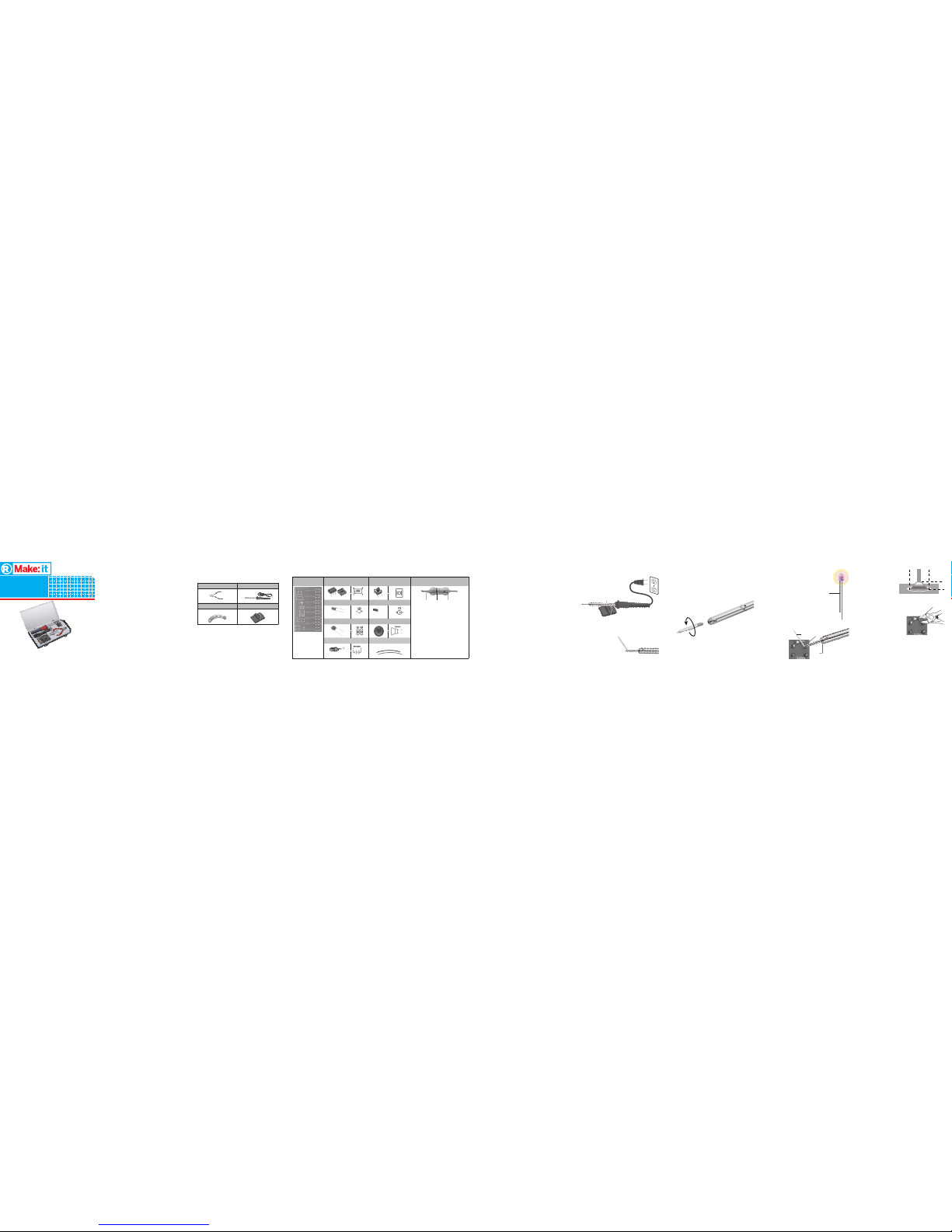
Assemble the Electronic Piano Kit
1Install the Resisters (R1 to R10)
Note: Resistorsare not polarized and can
be inserted facing eitherdirection.
1. Matchandinstallthe10resisters
(R1 to R10) to the resistorholes
(also labeled R1 to R10) on the
PCB.
2. Bend the leads close to the
resistor.
3. Solderandtrimtheexcessleads.