Press the button
(10 times).
Press the button once.
Press the button
(20 times).
Press the button once.
Press the button once.
The power save function
works immediately after
the soldering iron is
placed on the iron holder.
When 10 minutes have elapsed
since the soldering iron was placed
on the iron holder, the temperature
drops to 200°C/400°F automatically
and the station enters the power
When 30 minutes have elapsed
since the soldering iron was placed
on the iron holder, power to the heat-
er will be automatically shut off (auto
power shutoff).
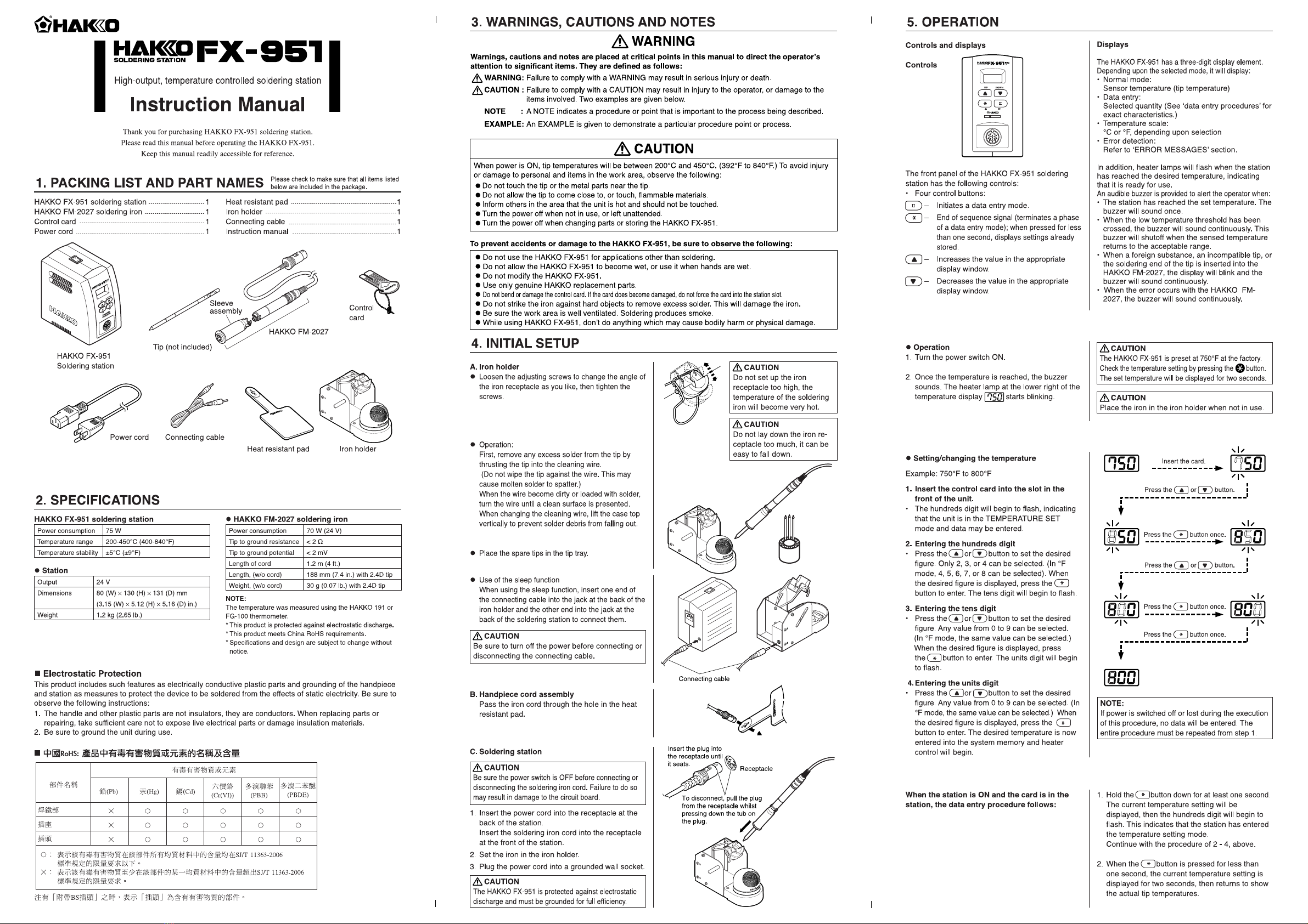
Press the or
button.
Press the button once.
Insert the card.
Press the or
button.
Press the button once.
Press the button
once.
Press the button.
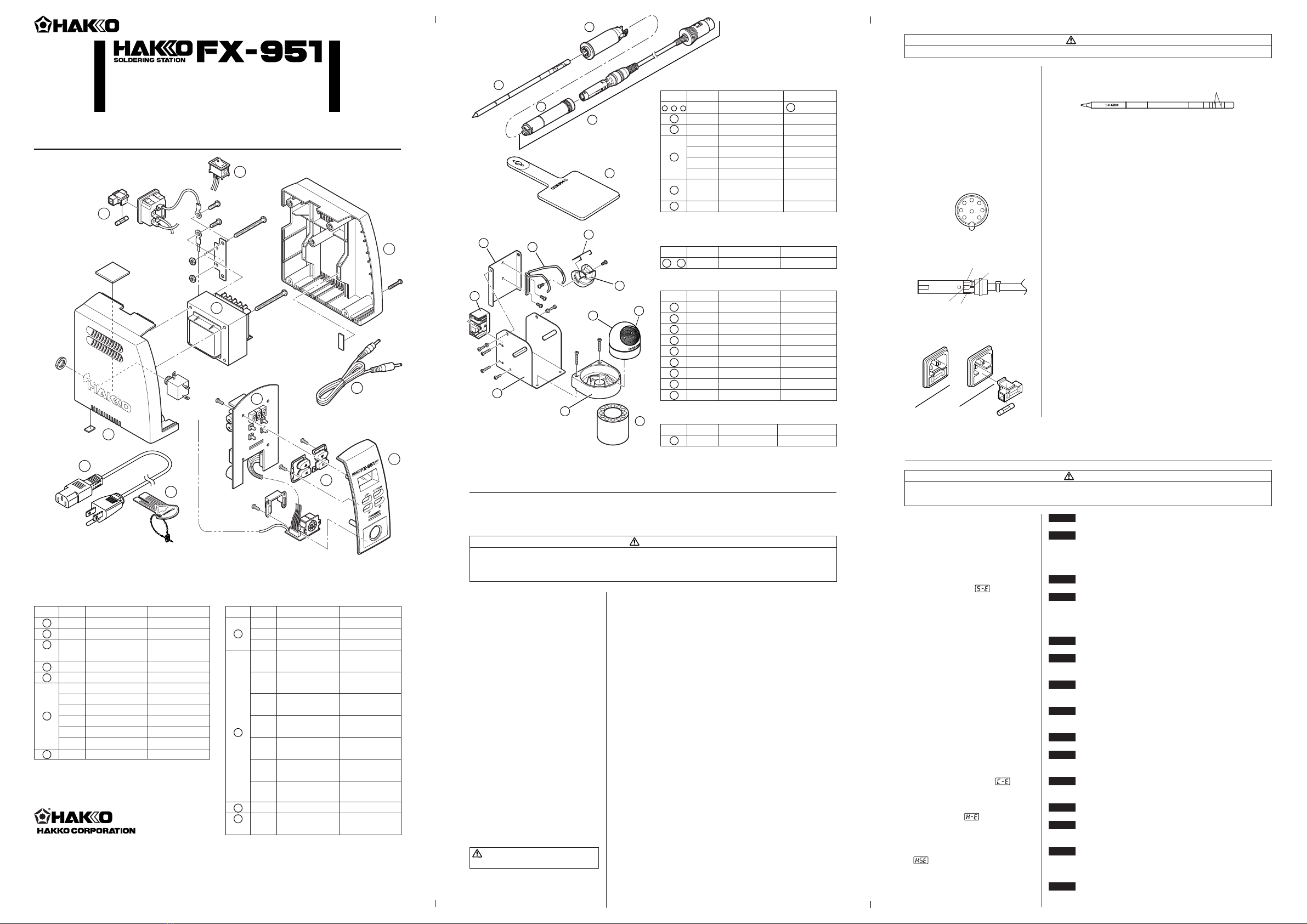
Remove the tip from the connector while pressing this part.
Hold the front part of the sleeve assembly to remove the tip.
Hold this part to insert the tip into the sleeve assembly.
Hold this part to insert the tip into the connector.
When there is the possibility that a failure has
occurred in the sensor or heater (including the
sensor circuit), is displayed and the power is
shut down.
CAUTION
The sensor error also occurs if the tip is not
inserted properly.
If the sensor temperature falls below the difference
between the current temperature setting and the
low-temperature alarm tolerance, is
displayed and the warning buzzer sounds. When
the tip temperature rises to a value within the set
tolerance, the buzzer will stop sounding.
EXAMPLE:
Assume that the temperature setting is
400°C/750°F and the tolerance 50°C/100°F. If the
temperature continues to decrease and finally
falls below the value indicated below while the
heating element is on, the displayed value starts
blinking to indicate that the tip temperature has
dropped.
will flash, and the buzzer will sound
continuously, when the tip is inserted wrong way
round, an incompatible tip is inserted, or a foreign
object has found its way into the connector.
will be displayed if the connector cord is not
attached to the station OR the wrong soldering iron
is connected.
7. ERROR MESSAGES
l Sensor Error
l Low-temperature alarm tolerance error
l Heater terminal short-circuit error
l Soldering iron error
3 Resetting the low temperature alarm
tolerance setting
The unique function alerts the operator when the sensed
temperature drops below a set limit. Should this occur, an
error message will be displayed, and the buzzer will
sound continuously. When the temperature returns within
the allowable range, the buzzer will stop.
Range of allowable low temperature alarm tolerance
for °C: 30 - 150°C
for °F: 50 - 300°F
Example:
When the setting temperature is 750°F and the low
temperature alarm tolerance is 200°F, buzzer will sound
when the tip temperature will drop over 550°F.
5. OPERATION 6. PARAMETER SETTINGS
The HAKKO FX-951 comes from the factory with
the following values preset.
Temperature scale Fahrenheit
Power save 0 min.
Low temperature alarm setting 300°F
Resetting the supervisor or 4 0
operator control setting
Setting temperature 750°F
l Entering the parameter
1 °C or °F temperature display
2 Power save setting
Set the time from the placement of the soldering iron on
the iron holder to the activation of the sleep function.
When the station enters the parameter input mode,
the procedure is as follows.
l
When the station enters low-temperature alarm tolerance
setting mode, the hundreds digit begins flashing. Enter
and store the value in the same manner as described in
“Changing the temperature setting.”
l
If you enter a value exceeding the allowable range shown
to the left, you will be brought back to entering a value in
the hundreds digit. If this occurs, reenter a correct value.
l
Once the value is stored, the system will automatically sequence
to resetting the supervisor/operator control setting mode.
350°C (400°C – 50°C)
Set temperature
Set temperature Low-temperature alarm tolerance
Low-temperature alarm tolerance
OR
650°F (750°F – 100°F)
EXAMPLE:
When the station is ON and the card is in the
station, the offset entry procedure follows:
1.
Hold the button down for at least one second.
The current offset value will be displayed, then the
hundreds digit will begin to flash. This indicates that
the station has entered the offset value input mode.
Continue with the procedure of a - c, above.
2.
When the button is pressed for less than one
second, the current offset value is displayed for two
seconds, then returns to tip temperature.
To change the supervisor/operator control settings,
the procedure is as follows.
l The display will show or when this
mode is entered.
: No offset value can be entered without
inserting the card.
: An offset value can be entered without
inserting the card.
Pressing the or button will change
and .
When the desired setting is displayed, select by
pressing button.
The system will exit the parameter setting mode
and begin heater control.
It is now ready for normal operation.
4 Resetting the supervisor/operator control
setting
l
When the auto-power shutoff function is activated and
power to the heater is shut off, the buzzer sounds three
times.
l
When the display shows , and to begin soldering,
cycle the power switch OFF, then ON.
NOTE:
When the unit is in offset-free mode, you can go
into the offset value entry mode without control
card by pressing the button for second.
1. Turn power OFF.
2. Insert the control card into the card slot in the
front of the unit.
3. Press and hold down the and buttons
simultaneously, and then turn power ON.
4. Hold and buttons down until the
display shows (Celsius) or
(Fahrenheit).
When either the display shows either or ,
the station is in parameter input mode.
lPressing either the and button will cause
the display to alternate between or .
l When the desired scale is displayed, select by
pressing the button. The system will
automatically sequence to power save mode.
l How to enter the tip offset value into the
HAKKO FX-951
Example 1;
If the measured temperature is 710°F and the set
temperature is 700°F, the difference is -10°F (need
to decrease by 10°F). So, enter the figure which 10
is deducted from present offset value.
1. Insert the control card into the slot in the
station.
• The station is in the temperature setting mode.
The hundreds digit will begin to flash.
2. Press the button on the front panel.
• This will set the station to offset value entry
mode.
3. Enter the offset value
The allowable ranges for offset values are from
-50 to +50°C (In °F mode from -90 to +90°F).
NOTE:
During offset data entry mode with blinking,
the tip temperature is controlled by present
offset value.
a. Entering the hundreds digit
• Press the or button to set the desired
figure. Only 0 (plus) or - (minus) can be
selected. (In °F mode, it is the same as °C
mode). When the 0 (plus) or - (minus) is
selected, press the button to enter. The
tens digit will begin to flash.
b. Entering the tens digit
• Press the or button to set the desired
figure. Any value from 0 to 5 (In °F mode, 0 to
9) can be selected. When the desired figure is
displayed, press the button to enter.
The units digit will begin to flash.
c. Entering the units digit
• Press the or button to set the desired
figure. Any value from 0 to 9 (In °F mode,
same value can be selected.) When the
desired figure is displayed, press the
button to enter. The desired temperature is
now entered into the system memory and
heater control will begin with new offset value.
l
The sleep function is activated and the temperature of
the tip begins to drop. The buzzer sounds once.
l
When the display shows , pressing any button
the power will be turned on again.
NOTE:
When not using the power save function, do
not connect the iron holder and the soldering
station with the connecting cable.
Power save example:
2 0 Sleep (immediately after the soldering iron
is placed on the iron holder)
210 Sleep (10 minutes after the soldering iron is
placed on the iron holder)
230 Auto-power shutoff (30 minutes after the
soldering iron is placed on the iron holder)
NOTE:
The power save time can be set in steps of
one minute (30 minutes max.)
NOTE:
The sleep function does not work in case the
setting temperature is less than 300°C/570°F.
CAUTION
•
Be sure to keep the lock release buttons hold down
while pulling out the sleeve assembly. Failure to do
so will damage the locking mechanism.
•
Be sure to pull out the tip only after separating the
sleeve assembly from the connector. Otherwise, the
sleeve assembly may fall down and break.
CAUTION
Insert the tip into the sleeve assembly until it
clicks into place. When you hear it clicks, avoid
forcing the tip into the sleeve assembly.
CAUTION
The tip may be hot. Avoid holding the hot tip for a long time even if using the heat-resistant pad. Otherwise burns may result.
lReplacing the tip
Removing the tip:
• Hold down the lock release buttons in the sleeve
assembly, pull out the tip together with the
sleeve assembly from the connector.
• Holding the front end of the sleeve assembly,
pull out the tip.
• Insert the tip securely into the connector.
Inserting the tip:
Holding the front end of the tip, insert it into the
sleeve assembly.
NOTE:
Improper insertion of the tip will cause to
appear on the display.
CAUTION
When holding the head of the tip, there is a danger of
burn. Be sure to use the heat-resistant pad.
The HAKKO FX-951 has the following four parameters:
1) °C or °F temperature display selection
2) Power save
3) Low temperature alarm setting
4) Resetting the supervisor/operator control
setting
Once the station enters parameter mode, set the
parameters in the order shown below. After all the
parameters have been set, normal operation will be
resumed.
2007.9
MA01349JZ070903
Copyright © 2004 HAKKO Corporation. All Rights Reserved.
OVERSEAS AFFILIATES
U.S.A.: AMERICAN HAKKO PRODUCTS, INC.
TEL: (661) 294-0090 FAX: (661) 294-0096
Toll Free (800)88-HAKKO
4 2 5 5 6
http://www.hakkousa.com
HONG KONG: HAKKO DEVELOPMENT CO., LTD.
TEL: 2811-5588 FAX: 2590-0217
http://www.hakko.com.hk
HEAD OFFICE
TEL:+81-6-6561-3225 FAX:+81-6-6561-8466
SINGAPORE: HAKKO PRODUCTS PTE., LTD.
TEL: 6748-2277 FAX: 6744-0033
http://www.hakko.com.sg
Please access to the following address for the other Sales affiliates.
http://www.hakko.com
The temperature accuracy of iron tips is ±15°C (±27°F) except for some tips.
If a higher temperature accuracy is required, use the following offset function: