Vitus Audio Reference Series User manual

REFERENCE
SERIES
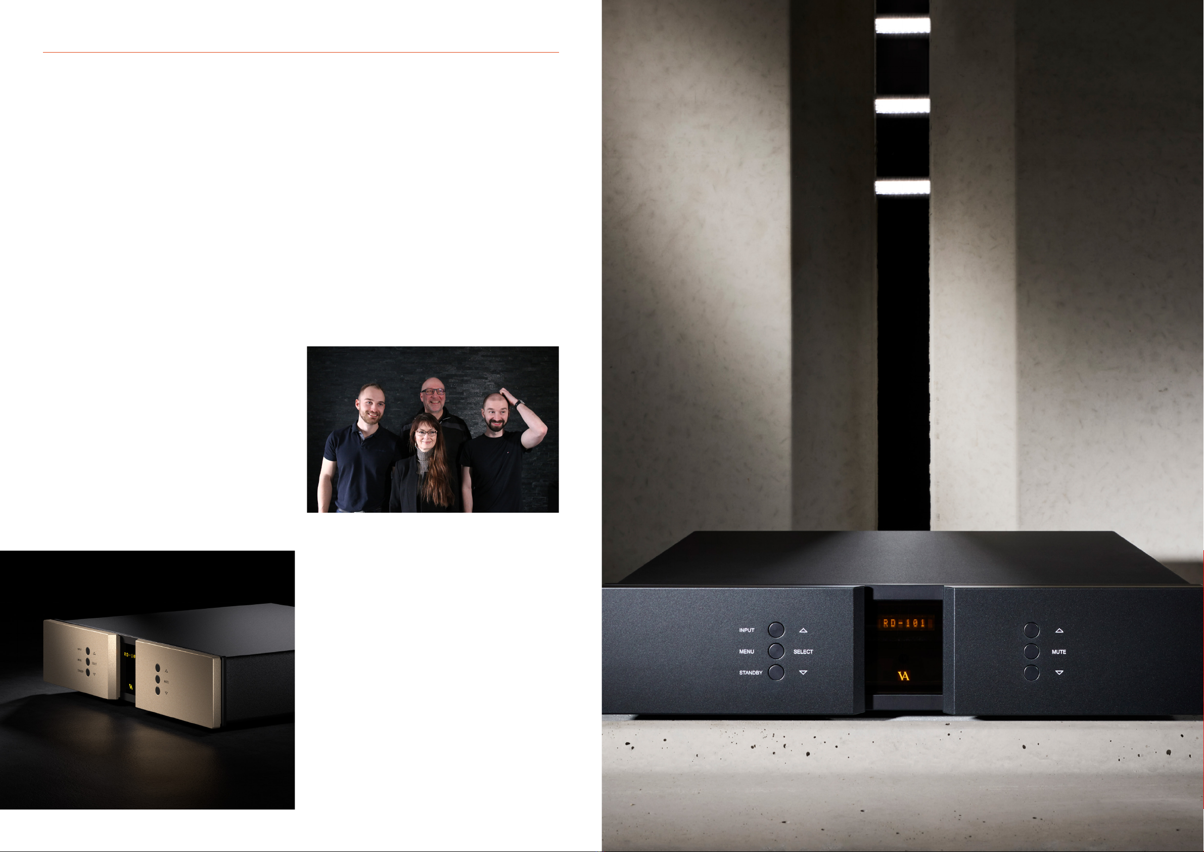
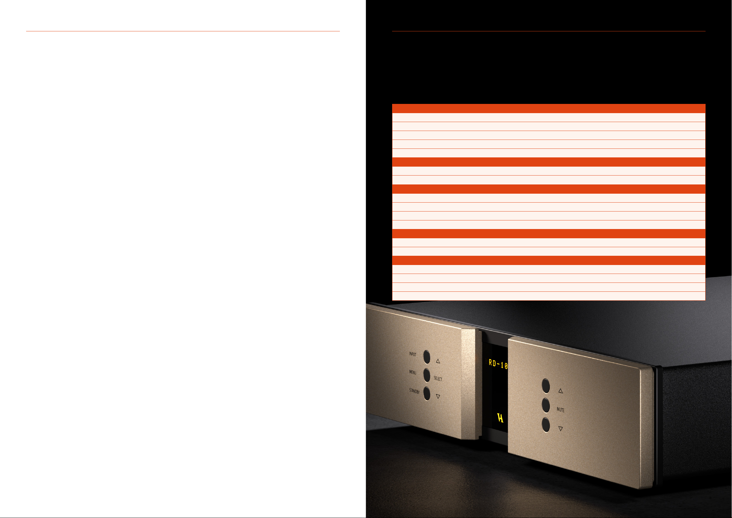
RD–101
REFERENCE
DA CONVERTER
OWNER’S MANUAL

RD-101 Owner’s manual | 32 | RD-101 Owner’s manual
From the creator
Foreword 4-5
Introduction
About this manual 6
Introduction to the Reference Series 7
1. Getting started
Unpacking the box, and how 8
to correctly unpack it
Heavy lifting – WARNING 8
What’s in the box 8
Device overview 9
The topology of the volume control 10
2. Connecting
Turning the RD-101 on and o 11
Connecting the RD-101 12
The rear panel 13
3. Operation
Operation modes 14-15
Functions – left front panel 16
Functions – right front panel 17
The elements in the menu 18-19
The RD-101 menu structure 21
4. Operation and service
Maintenance 22
Mains supply voltage 22
Mains fuse 23
Fuse type 23
Replacing a blown fuse 24-25
Firmware updating 26-27
5. Warranty
Warranty 28
6. Specications
RD-101 Specications 29
7. Examples operation
Changing oset volume for inputs 31
Changing display brightness 32
Changing initial volume step 33
Disabling inputs 34
Changing input names 35
Setting xed volume for inputs 36
Conguring auto standby 37
Restore factory settings 38
CONTENTS
4 | RD-101 Owner’s manual
FROM THE CREATOR
Foreword
First of all, thank you for choosing the Vitus Audio RD-101
Reference DA Converter, we are sure you will enjoy it for many
years to come. When purchasing a Vitus Audio product, you are
guaranteed a musical performance, which exceeds the current
musical standards. Vitus Audio is dedicated to musical performance
rather than technical details and high performance measures.
At Vitus Audio everything works until proven not to. This way we
always try to push the limits and explore the unexplored. As a result
of this, many of the solutions we use today are considered to be
“impossible to ever get working”, however they have convinced
many people and reviewers world wide of the opposite. Before any
of our new topologies are implemented in our products, they are
carefully reviewed by our dedicated listening panel. This way we can
guarantee the correct level of musically performance and robustness.
Generally we’re after super neutral, super detailed and super dynamic
reproduction without “loosing” the nerve in the music which often
is a drawback of many high end ampliers. Our real strongholds are
complete silence, unbelievable depth and width in the soundstage
resulting in a far more open sound with higher resolution – you could
say, closer to the artist. As a result of the above, our ampliers do not
“focus” on any specic frequencies - i.e. no extension of top or bass,
which of course results in high clarity of the midrange since
it’s “naturally present”!
Hans Ole Vitus | Founder
RD-101 Owner’s manual | 5

INTRODUCTIONINTRODUCTION
This is your RD-101 owner’s manual. The following pages will,
as clearly as possible, describe how to get your RD-101 operating
quickly and easily. Although some operations are self-explanatory,
we strongly suggest you read this manual to avoid any damage to
the unit. The manual is designed to be helpful. If there are points you
feel we could cover better, or that we have missed out – please tell
us by sending an email with your nding to: sales@avagroup.nu
Reference Series is your entry point to the world of Vitus Audio.
The components in this series are cost-optimised versions of the
products in our Signature Series. Although the cost is lower, this
does not mean we have compromised on results. As with every Vitus
Audio product, the sound you experience remains breathtaking.
About this manual Introduction to the Reference Series
RD-101 Owner’s manual | 76 | RD-101 Owner’s manual
8 | RD-101 Owner’s manual
1. GETTING STARTED1. GETTING STARTED
What’s in the box, and how
to correctly unpack it
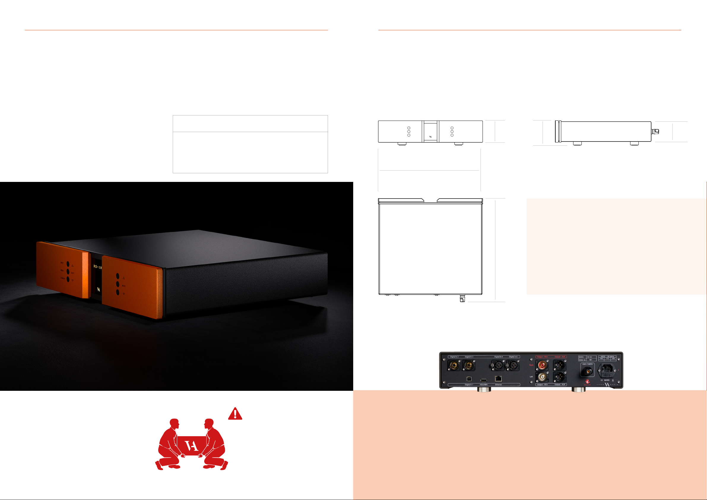
RD-101 device overview
Gently cut open the tape on the top of the box, making sure not
let the knife protrude too much. Open the box and remove the
foam top with all the included accessories. Next, remove the 4
foam corners from the front and back of the product. With two
people, carefully lift the amplier out of the box.
Store the empty box and protective foam for later use.
Box contents
RD-101
Mac Remote
Power Cable
USB with Manual and Brochure
Foam top 1
Foam top 2
Foam Sides 6 pieces
Foam bottom
This amplier is VERY heavy.
Make sure that you have at least
two people when unpacking and
moving the unit. You might damage
both your back and the amplier if
extra care is not taken. AVA Group
A/S cannot be held responsible
for any damage incurred as a result
of careless handling of the unit.
RD-101 Owner’s manual | 9
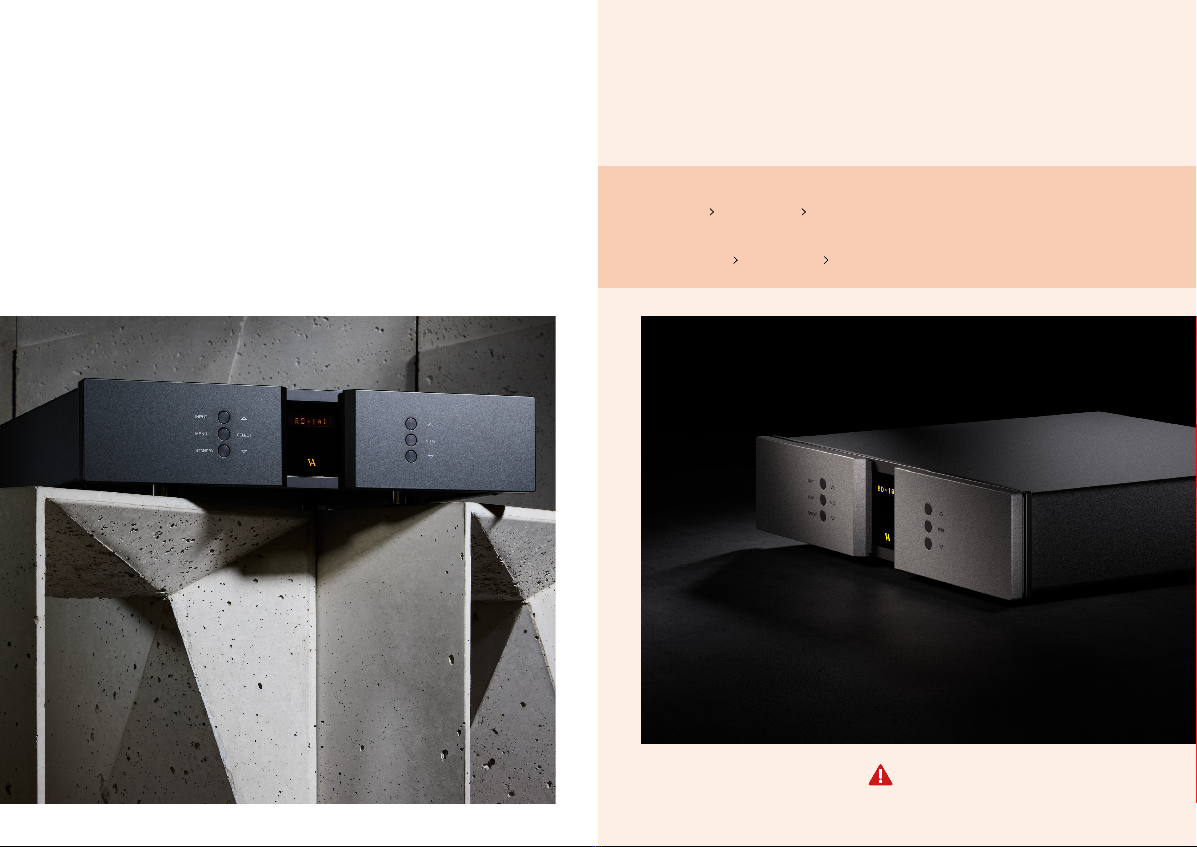
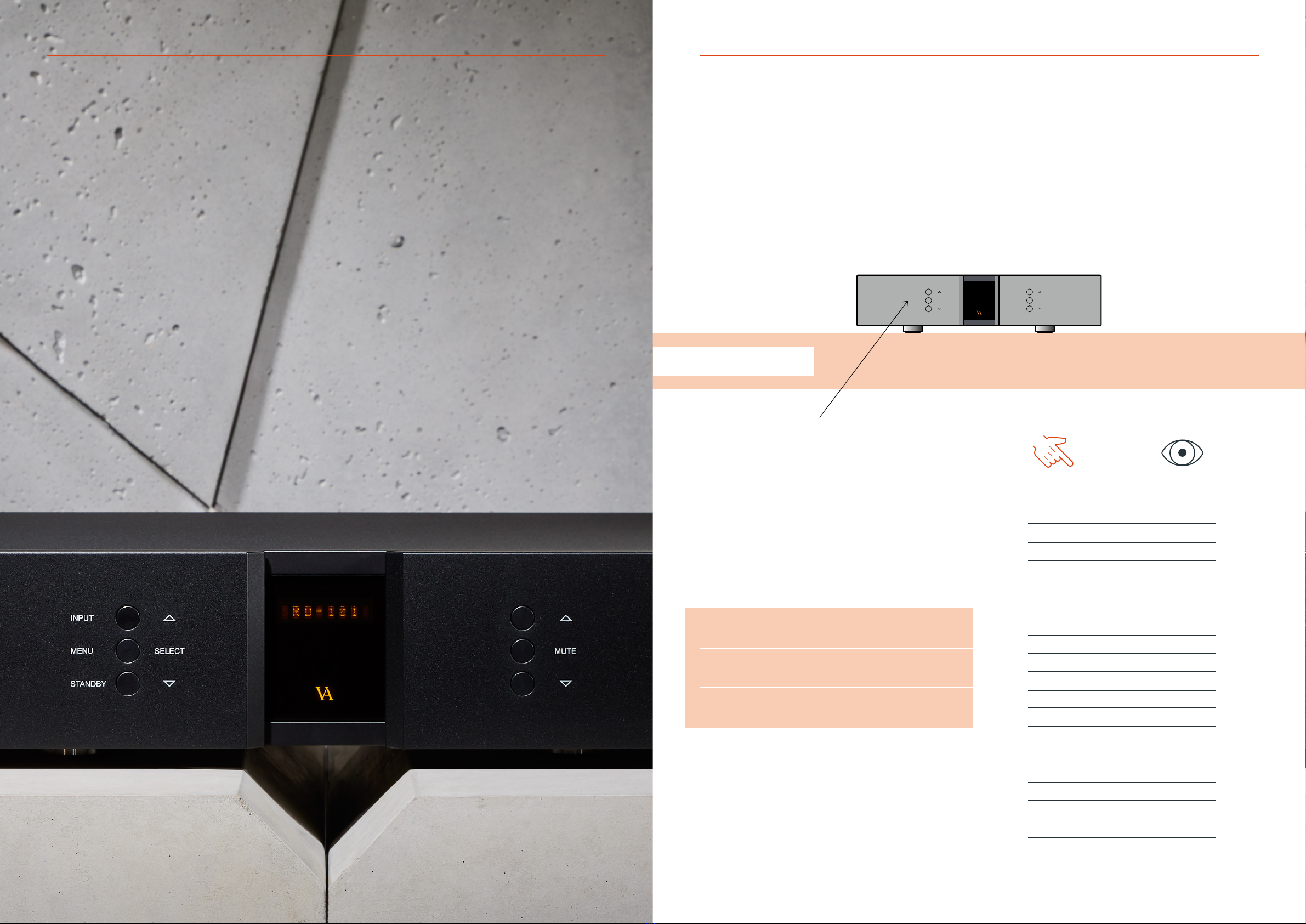
SELECT
INPUT
MENU
STANDBY
MUTE
Material: Aluminium for body parts
Dimensions (H x W x D): 103 x 435 x 431 (mm)
Total weight: 12Kg
431 mm
90 mm
85 mm
103 mm
435 mm
Not following this procedure, may cause damage to any
of your products/speakers. Damage caused by not following
this procedure will invalidate the warranty.
2. CONNECTING
Turning the RD-101 on and off
RD-101 Owner’s manual | 11
1. GETTING STARTED
10 | RD-101 Owner’s manual
Always turn on the products beginning from the source:
Source pre-amplier power amplier
Always turn o your products in reverse order:
Power amplier pre-amplier Source
The topology of the volume control used in the RD-101 is very
dierent compared to the “standard”. The RD-101 uses a series of
xed resistor networks to control the volume. Relays are used to
switch between the resistor networks. Across all volume steps, a
xed resistor is in series with the signal path. This gives the best
performance possible. When you change volume, a dierent
number of shunt resistors are used.
The topology of the volume control
To prevent pop in the output, we have chosen to rst add the new
shunt resistors, and then wait a short time, before removing the
unused shunt resistors at the new volume step. This will give a minor
fall in volume before settling at the new volume step. It takes very
little time to get used to this type of operation of the volume, and
it will give you superior sound quality over the traditional digital
and analogue potentiometers.
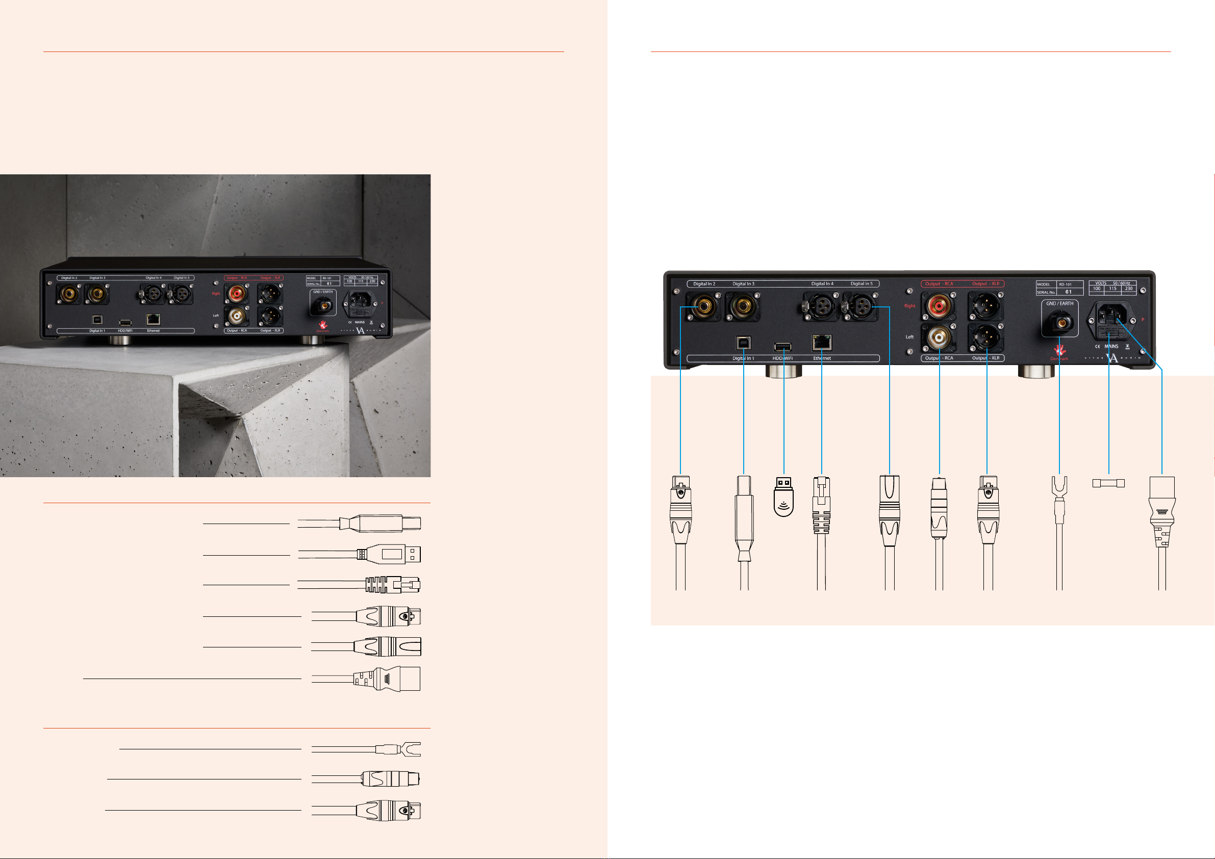
Connecting the RD-101 The rear panel
2. CONNECTING2. CONNECTING
Digital inputs
Input
WI-FI
Ethernet
Input
Input
Power
Digital inputs
USB B
USB A
RJ45
S/PDIF
AES
USB B in
WI-FI dongle in
Ethernet in
RCA
3 pin XLR
C13/C15 IEC
Outputs
Ground / Earth
Output RCA
Output XLR
Ground
RCA
3 pin XLR
12 | RD-101 Owner’s manual RD-101 Owner’s manual | 13
Digital XLR in
Ethernet RJ45 in
Digital USB in
WI-FI dongle
Analogue XLR out
Digital RCA in
Analogue RCA out
Ground
Power
Fuse
Place the RD-101 on its shelf.
Connect all the sources to the
inputs of the RD-101 labelled
INPUT 1 to 5 on the rear panel.
Connect the output of the
RD-101
Lastly connect the mains to
the DAC, after you have
connected both inputs and
outputs.
ATTENTION: Never plug in/
unplug any cables within the
whole of the system while the
RD-101 is operational. Always
set the RD-101 into standby
mode before making any system
adjustments.

RD-101 Owner’s manual | 15
3. OPERATION3. OPERATION
Operation modes
The RD-101 has 3 operation modes
1. NORMAL
This is the mode you use when listening to music.
2. MENU
In this mode you can alter the settings of the RD-101.
3. STANDBY
In this mode the controls of the RD-101 are deactivated.
14 | RD-101 Owner’s manual
SELECT
INPUT
MENU
STANDBY
MUTE
SELECT
INPUT
MENU
STANDBY
MUTE
3. OPERATION3. OPERATION
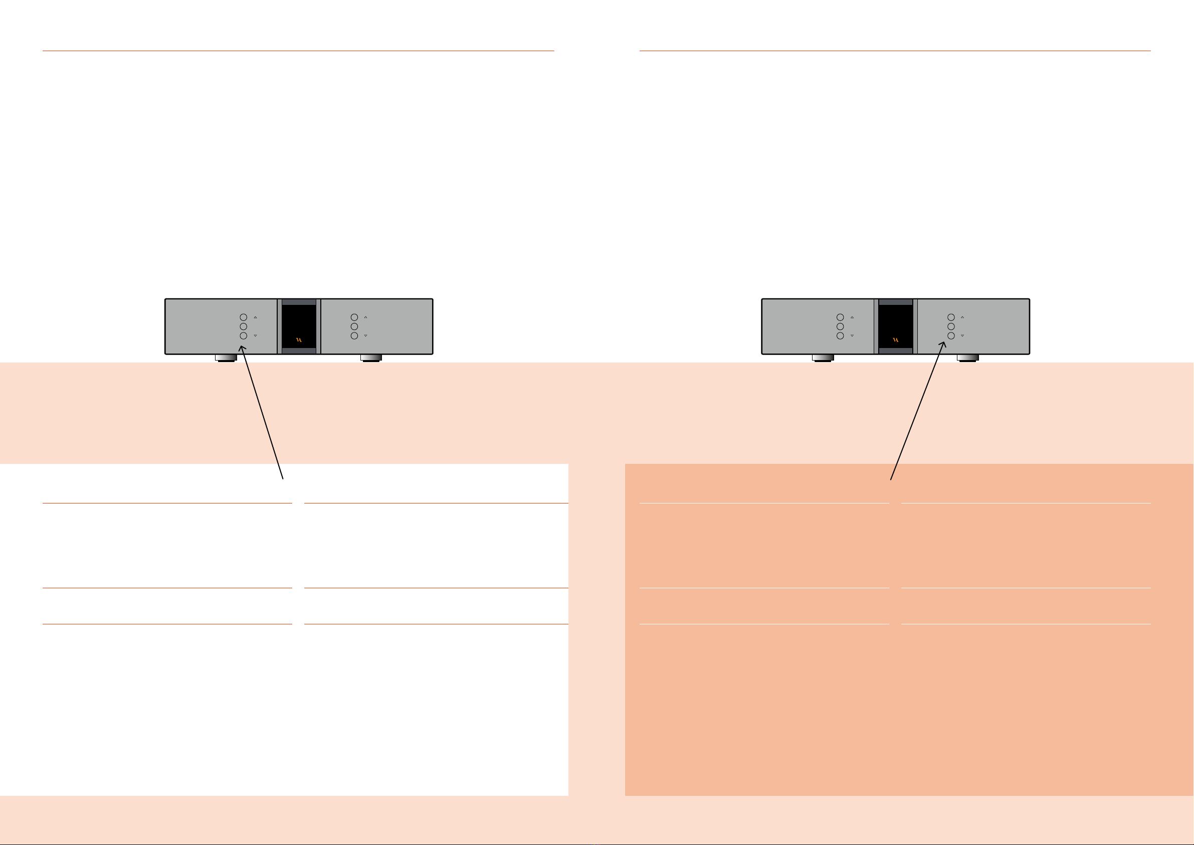
Functions –left front panel Functions –right front panel
Normal mode
In normal mode there are 3 basic functions/buttons available
on the left-hand side at the front of the unit.
1. INPUT
Selects between the 6 inputs.
2. MENU
Switches to “Menu mode”
3. STANDBY
Switches in and out of “Standby Mode”
Menu mode
You enter menu mode, by pushing the “MENU” button
once in Normal mode. In the Menu mode there are 3 basic
functions/buttons as follows:
1. r
Scroll forward in the menu
2. MENU/ SELECT
Enter and Exit submenus and select settings
3. s
Scroll backward in the menu
Normal mode
In normal mode there are 3 basic functions/buttons
available on the right-hand side at the front of the unit.
1. r
Turns volume up
2. MUTE
Mutes the output
3. s
Turns volume down
Menu mode
In the text-menu it is possible to change the name of the input.
This is done by using the following buttons:
1. r
Change selected character
2. MUTE
Go to the next character in the display
3. s
Change selected character
RD-101 Owner’s manual | 1716 | RD-101 Owner’s manual

18 | RD-101 Owner’s manual
3. OPERATION3. OPERATION
The elements in the menu The elements in the menu
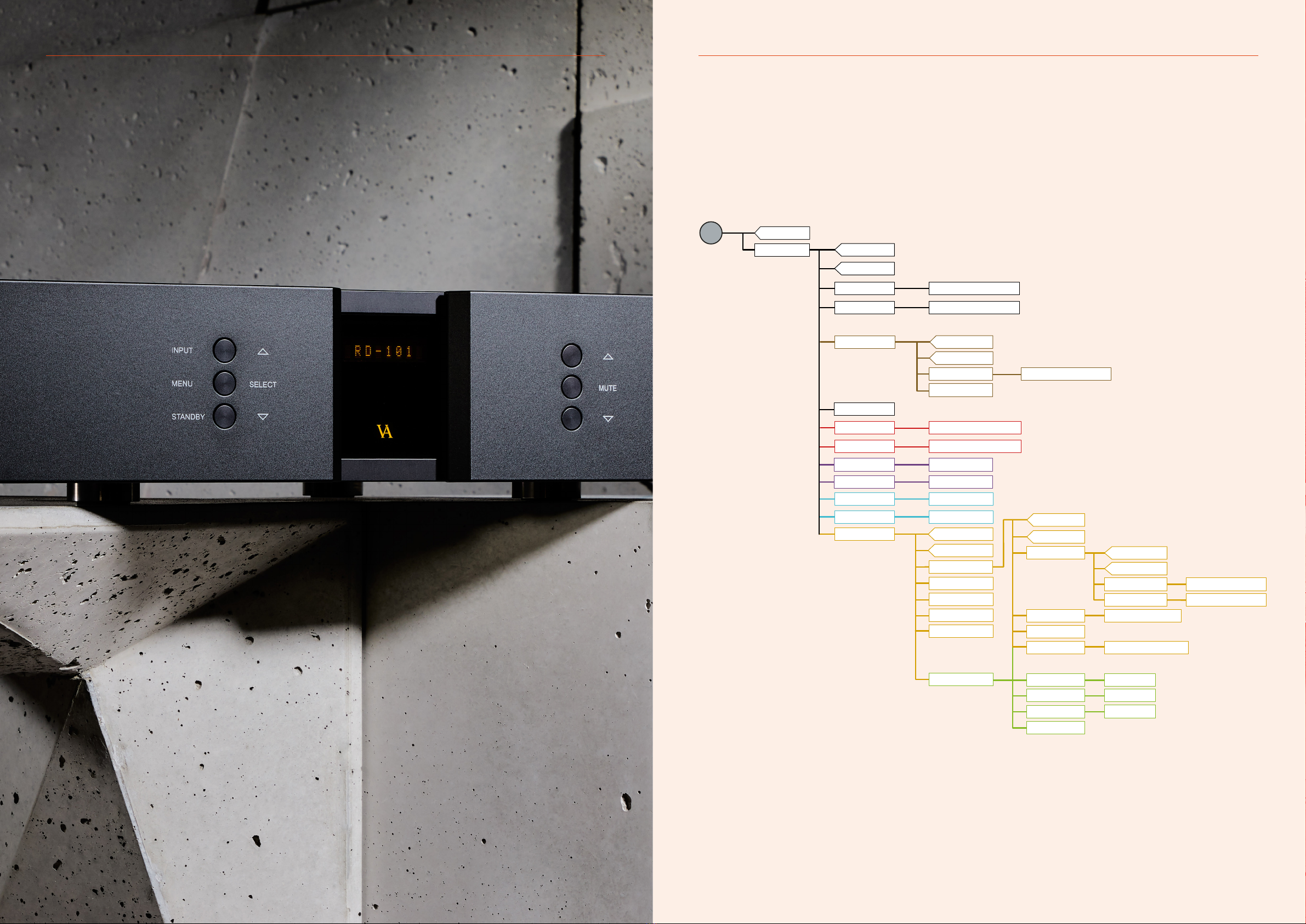
You can modify the settings of your RD-101 by entering the menu and selecting
the options you require. Refer to the menu structure diagram on page 21 for specific
information.
The sub-menus are highlighted in different colours.
SETUP, OUTPUT, REMOTE, AutoStb, RESET, V.INIT, BP VOL, LOGO, BRIGHT, INPUTS
See chapter 7 for options on modifying settings.
SETUP
Change the settings of the RD-101.
OUTPUT
Here you can switch between RCA OUT and XLR OUT.
REMOTE SETTINGS
The RD-101 is standard shipped with a Apple Remote.
The Apple remote that comes with the RD-101 can be used
on all Reference devices. If you own two (or more) reference
devices than it is recommended that you pair the remote(s)
with their devices.
REMOTE ID
Show the ID of the remote.
UNPAIR
Un-pair the remote and the RD-101 by removing the REMOTE ID.
DATA
Shows information about this RD-101.
AutoStb
Choose if the product should automatically enter standby mode
afterthe buttons on the remote or on the front of the unit haven’t
been used for X minutes.
RESET
Restore the settings of the RD-101 to its default settings.
V.INIT
Change settings for the initial volume step of the RD-101.
The RD-101 has a default volume step of -50 dB. You can set the
volume step to a step, between -99.0 dB to +12 dB.This step will
be the new volume step. Even when after the power cord has
been disconnected the RD-101 still starts up in the new volume step.
BP VOL
Switch between BP OFF (enable volume control) or BP ON (disable
volume control).
LOGO
Turn ON/OFF the VA logo on the front panel
BRIGHT
Change the brightness of the display to 0, 1, 2 or 3.
INPUTS
Change settings for each input.
INPUT (1-5)
The RD-101 has 5 analog inputs.
The settings for each individual input can be adjusted in the menu.
The input selection is saved automatically every 10 minutes.
Each time you initialise the RD-101 the last saved setting is restored.
You can manually save a setting by pressing the MENU button
down 2-3 sec. When “SAVE” is shown in the display, the setting
has been saved.
STREAMER
Here you can set the RD-101 to automatically check for rmware
updates for the streamer. In the streamer settings the update check
can be enabled/disabled. (note: all rmware updates made available
are tested and approved by Vitus Audio).
INPUT NAME SETTINGS
By default, the inputs are named DIG 2/3/4/5, USB and Streamer.
In the text-menu you can nd a list of predened input names.
If the name of your device is not in the list, you can choose to make
your own device name.
ADJUST
Adjust the xed dB step to any step between -89 dB and +13dB.
This function is only available when FIX ON is selected.
SET FIX
Lock and unlock the volume on a specied input by switching
between FIX ON/FIX OFF.
This feature can be used to congure a home theater bypass input,
if the amplier is used with a surround processor. Input X is now
locked to the SET FIX dB step and can’t be adjusted with the
volume control.
OFFSET
Oset volume setting.
Dierent sources often have dierent output voltages. This has
a direct inuence on the typical volume level that is needed for a
specic sound level, hence changing between sources can result in
a high sound level dierence. To accommodate easy operation, we
have included an oset volume in our ampliers – it simply osets
the volume starting point at a specic volume to match the source.
The oset-value can be set from -12 dB to +12 dB.
SENS
Devices can have dierences in output level. You can adjust the
sensitivity of each input between ≤ 2 Vrms, ≤ 4 Vrms, ≤ 8 Vrms to
minimize these dierences and to prevent clipping of the input.
The sensitivity level needs to be higher than the input level.
TEXT
Lets you change the name of a specied input.
By default the inputs are named input 1, input 2, etc. A list of
predened input names can be found in the text-menu. If the name
of your device is not on the list, you can choose to make your own
device name.
USED
Activates or disactivates specied inputs.
If you only use some of the inputs, it is possible to disable the
inputs that are not used. Using the “Input” button, the system skips
the disabled inputs, and jumps to the next used input.
RD-101 Owner’s manual | 19
with FIX ON and VOL BP OFF
with FIX OFF and VOL BP OFF
**
BACK
BACK
EXIT
FIXED BACK
EXIT
ADJUST -90 dB / +0 dB
SET FIX FIX ON / FIX OFF
-12 dB / +12 dB
USED / NOT USED
OFFSET
TEXT
USED
EXIT
INPUT 5
INPUT 4
INPUT 2
INPUT 3
USB
0 / 1 / 2 / 3
ON / OFF
CHK UPD
GAPLESS ON / OFF
ON / OFF
ON / OFF
APP VOL
STMINFO
Streamer
***
*** ***
*****
*
BRIGHT
LOGO
INPUTS
Use this setting with extra care.
One accidental click could turn
the volume up to 0 dB.
**
Not available on streamer input
*****
****
*
RES. NO / RES. YES
SETUP
MENU
EXIT
BP OFF / BP ON
XLR OUT / RCA IN
o – 360 (min)
BACK
EXIT
REMOTE ID
-90dB /+0dBV.INIT
ENA REM REM ON / REM OFF
***
***
BACK
EXIT
DATA
RESET
AutoStb
REMOTE
VOL BP
OUTPUT
BP VOL ON / OFF
3. OPERATION3. OPERATION
The RD-101 menu structure
RD-101 Owner’s manual | 2120 | RD-101 Owner’s manual

4. OPERATION AND SERVICE
Operation and service Operation and service
Maintenance and safety notice
Vitus Audio products are designed to run for many years without
the need for regular maintenance.
The Vitus Audio RD-101 contains no user serviceable parts except
from the mains fuse. Do not attempt to open the case as there are
potentially dangerous voltages present inside. Should your RD-101
show signs of malfunction, then please contact your dealer
or Vitus Audio.
Mains fuse
The mains fuse is accessible from the outside of the amplier. You
will nd the mains fuse, just below the power inlet. If the fuse blows,
you can easily replace it. The fuse only blows on the occurrence of
power surges or if there is a fault in the unit. Normally power surges
cause no other damage other than blowing the fuse. When the fuse
blows repeatedly on replacement, then the unit most likely has a
malfunction. In case of malfunction the unit must be returned to
Vitus Audio for repair.
Fuse type:
Physical size - 20 x 5mm
240V - 6.3A T (Time lag fuse)
230V - 6.3A T (Time lag fuse)
115V - 12A T (Time lag fuse)
100V - 12A T (Time lag fuse)
Replacing the fuse with a fuse of a type and rating dierent from
the original, might result in damage to the unit and injury to you
(the user). Damage to the unit as a result of incorrectly replacing
the mains fuse, will invalidate the warranty.
For an explanation of how to replace the fuse see chapter 4
“replacing a blown fuse”.
Mains supply voltage
Any unit may be set for operation in 100V, 115V or 230V/240V AC.
The units shipped are set for the mains supply voltage of the
destination. The mains supply voltage can be changed in the product.
In some cases, this work can be performed by our authorised partners
around the world. In rare cases we would ask that the product is
returned to the Vitus Audio factory in Denmark for the conversion
to be done.
22 | RD-101 Owner’s manual
4. OPERATION AND SERVICE
RD-101 Owner’s manual | 23
4. OPERATION AND SERVICE
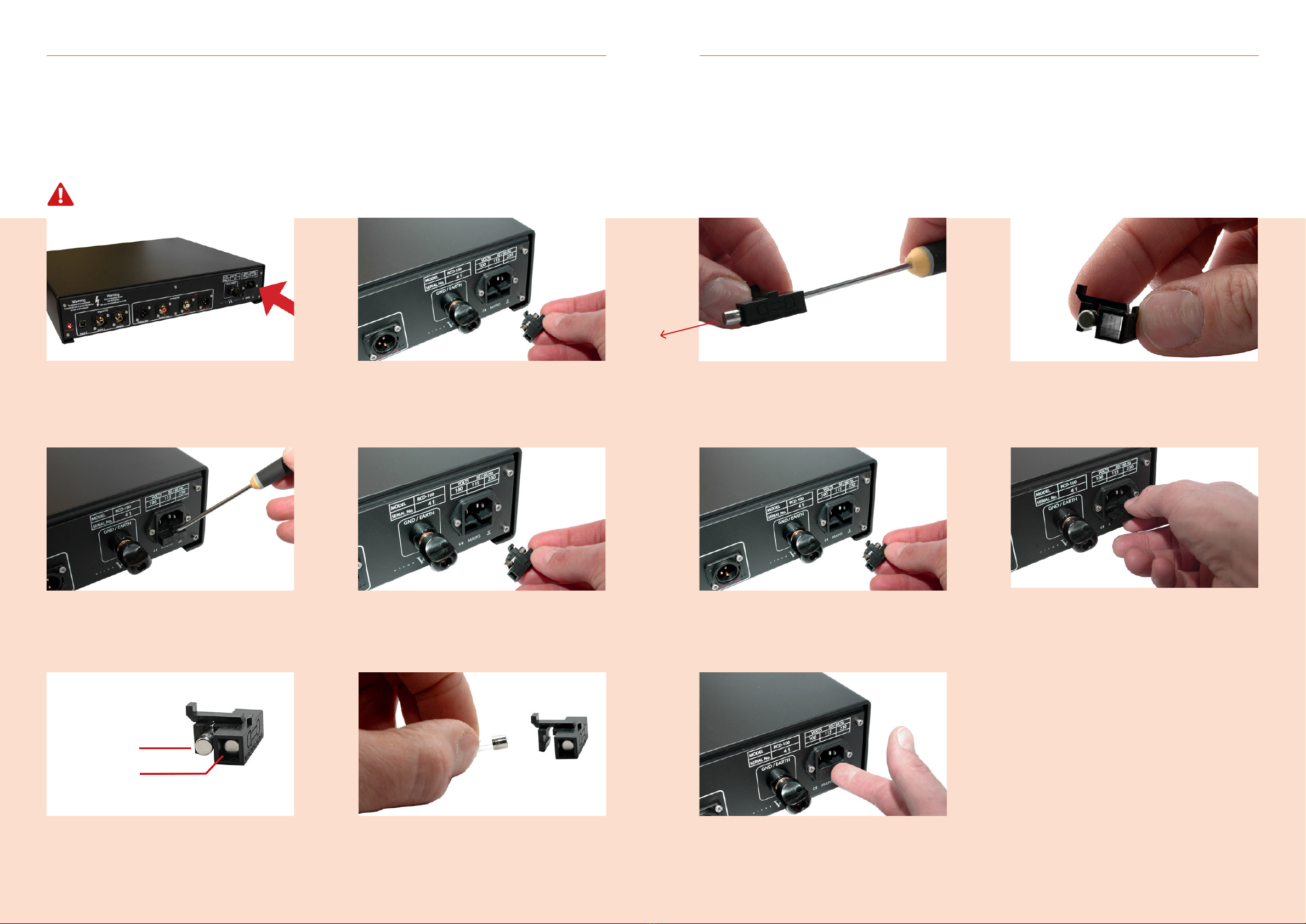
1.
The fuse carrier is placed on the back of the external
power supply under the power connector.
2.
Loosen the fuse carrier using a at object like a at screwdriver.
3.
Pull the fuse carrier out.
4.
Pull the fuse carrier out.
5.
There is a spare fuse available in the fuse carrier.
6.
Take the blown fuse out of the fuse carrier
and throw it away.
REMOVE THE POWER CABLE
24 | RD-101 Owner’s manual
Blown fuse
Spare fuse
4. OPERATION AND SERVICE
8. 9.
Push the fuse carrier into the back.
10.
The fuse carrier is in place when you hear “CLICK”.
7.
Push the spare fuse out using a pointy object.
7.
Place the spare fuse in the fuse carrier and click the fuse
in place.
Replacing a blown fuse Replacing a blown fuse
RD-101 Owner’s manual | 25
26 | RD-101 Owner’s manual RD-101 Owner’s manual | 27
Firmware updating Firmware updating
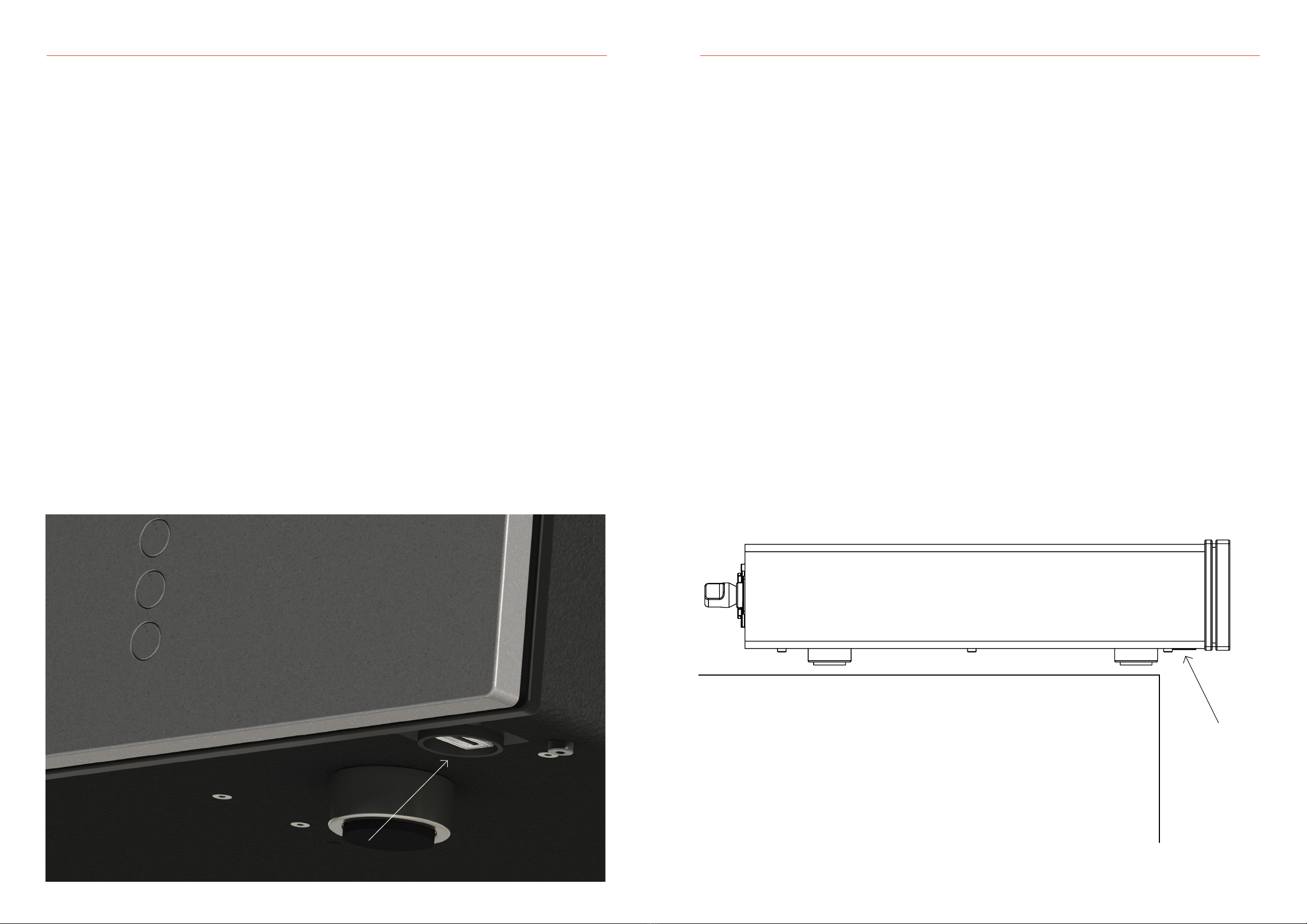
Firmware updating the RD-101
The rmware on the RD-101 can be updated via the USB service
port, located at the bottom right side, towards the front of the
product. See the image below for an overview.
Firmware updates would be rolled out in case of minor bug xes
or when adding extra features to the product.
You can contact your local Vitus Audio dealer if you are uncertain
if your product contains the latest rmware.
Firmware update procedure
1. Copy the .bin le onto an empty USB-Drive.
2. Put the amplier into standby mode and then turn o the product completely, by unplugging
the power chord from the product. Make sure to follow the instructions on page 11 of this manual.
3. Insert the USB-Drive into the service port, located at the bottom toward front left side.
4. Plug the power chord into the RD-101.
5. The display will show “new FT detected” while updating (this takes about 5 seconds).
6. When completed, the display will show “Done update” and the amplier will go into standby mode.
The rmware has now been updated and you may proceed to turn on the amplier in the correct
sequence and use it as normal.
USB drive formatting
Before transferring the rmware (.bin) le onto a USB drive,
make sure that it has been formatted to FAT or FAT32 format.
The USB drive should be empty of other data when the le
is being transferred and the rmware being updated.
USB service port
To access the service port easily on the RD-101, you can slide the product
towards the front edge of the platform the product sits on, as shown in the illustration below.
4. OPERATION AND SERVICE4. OPERATION AND SERVICE
USB service
port
28 | RD-101 Owner’s manual
5. WARRANTY
1. TERMS AND CONDITIONS
LIMITED WARRANTY
Vitus Audio warrants the product designated herein to be free of
manufacturing defects in material and workmanship, subject to the
conditions hereinafter set forth, for a period of two (2) years from
the date of purchase by the original purchaser or no later than six
(6) years from the date of shipment to the authorised Vitus Audio
cooperating partner, whichever comes rst, excepting any cosmetic
damage to chassis parts. (See 6)
2. CONDITIONS
This Warranty is subject to the following conditions and limitations.
The Warranty is void and inapplicable if the product has been used
or handled other than in accordance with the instructions in the
owner’s manual, abused, or misused, damaged by accident or neglect
or in being transported, or the defect is due to the product being
repaired or tampered with by anyone other than Vitus Audio or
authorised Vitus Audio repair center. The product must be packed
in its original box and returned to Vitus Audio or an authorised repair
center by the customer at his or her sole expense. Vitus Audio will
pay return freight of its choice.
IMPORTANT!
A returned product MUST be accompanied by a written description
of the defect and a photocopy of the original purchase receipt.
This receipt must clearly list model and serial number, date of
purchase, the name and address of the purchaser and authorised
dealer and the price paid by the purchaser. Vitus Audio reserves
the right to modify the design of any product without obligation to
purchasers of previously manufactured products and to change the
prices or specications of any product without notice or obligation
to any person.
3. LIMITED TO ORIGINAL PURCHASER
This Warranty is for the sole benet of the original purchaser of
the covered product and shall not be transferred to a subsequent
purchaser of the product.
4. DURATION OF WARRANTY
This Warranty expires on the second (2nd) year anniversary of the
date of purchase or no later than the sixth (6th) anniversary of the
date of shipment to the authorised Vitus Audio cooperating partner,
whichever comes rst.
5. CHASSIS
Damage or cosmetic defects are not warranted.
6. DEMONSTRATION EQUIPMENT
Equipment used by an authorised cooperating partner for
demonstration purposes is warranted to be free of manufacturing
defects in materials and workmanship for a period of three (3) years
from the date of shipment to the authorised cooperating partner.
After the rst year, demo equipment needing warranty service must
be packed in its original box and returned to Vitus Audio by the
cooperating partner at his or hers sole expense. Vitus Audio will pay
return freight of its choice. A returned product must be accompanied
by a written description of the defect on a VITUS AUDIO RETURNED
GOODS AUTHORISATION form. Dealer-owned demonstration
equipment sold at retail within three (3) years of date from shipment
to the dealer is warranted to the rst retail customer to be free of
manufacturing defects in materials and workmanship for the duration
of the three (3) Year Limited Warranty remaining (as measured from
the date of shipment of the equipment to the Vitus Audio partner.
In the event warranty service is needed under these conditions, the
owner of the equipment must provide a copy of his purchase receipt,
fullling the requirements described under ”2. Conditions” above.
The product must be packed in its original box, and returned to Vitus
Audio or an authorised Vitus Audio repair center by the customer
at his or her sole expense. Vitus Audio will pay return freight of
its choice.
7. MISCELLANEOUS
Any implied warranties relating to the above product shall be limited
to the duration of this warranty. The warranty does not extend to
any incidental or consequential costs or damages to the purchaser.
Some countries do not allow limitation on how long an implied
warranty lasts or exclusion or limitation of incidental or consequential
damages, so the above limitations or exclusions may not apply to
you. This warranty gives you specic legal rights, and you may also
have other rights which vary from country to country.
8. WARRANTOR
Inquiries regarding the above Limited Warranty may be sent to the
following address:
AVA Group A/S
Hammershusvej 3H
DK7400 Herning Denmark
Att. Customer Service
Before sending any products to the above address, an RMA case
number has to be issued. This can be obtained after initial dialogue
with our service department which is initiated by lling out the
“service and upgrade” webform on our website, with all the required
information.
Information required:
Copy of original purchase invoice
Serialnumber
Detailed description of problem
9. WARRANTY OUTSIDE OF DENMARK
Vitus Audio has authorised distribution in many countries in
the world. In each country, the authorised importing retailer or
distributor has accepted the responsibility for warranty of products
sold by that retailer or distributor. Warranty service should normally
be obtained from the importing retailer or distributor from whom
purchased your product. In the unlikely event of service required
beyond the capabilities of the importer, Vitus Audio will fulll the
conditions of the warranty. Such products must be returned at
he owner’s expense to the Vitus Audio factory, together with a
photocopy of the bill of sale for that product, a detailed description
of the problem, and any other information necessary return shipment.
In many cases the retailer your purchased the product from, will
handle this for you.
10. FURTHER INFORMATION
Should you have any further questions related to our warranty,
please contact us at the following email: service@avagroup.nu
RD-101 Specifications
6. SPECIFICATIONS
RD-101 Owner’s manual | 29
OUTPUT XLR Analog RCA Analog
Available 1 (L+R) or 1 (L+R)
Impedance 75Ω 75Ω
Frequency response +800kHz +800kHz
Signal to noise ratio >110dB @ 1kHz >110dB @ 1kHz
THD + noise <0.01% <0.01%
DAC
Master clock 24.576 MHz +/- 5ppm
DAC ES9028PRO
DIGITAL AUDIO INPUT USB AES/EBU S/PDIF Streamer
Available 1x USB B 2x XLR 2x RCA 1x RJ45
Impedance 110Ω 75Ω
Sample rate 384 kHz + DSD128 192kHz 192kHz 192kHz + DSD 64
Resolution 24bit 24bit 24bit 24bit
POWER CONSUMPTION
Standby <1W
Operation 25W
DIMENSIONS
Height 103mm including feet
Width 435mm
Depth 396mm / 431mm with binding post
Weight 12kg
RD-101 Owner’s manual | 31
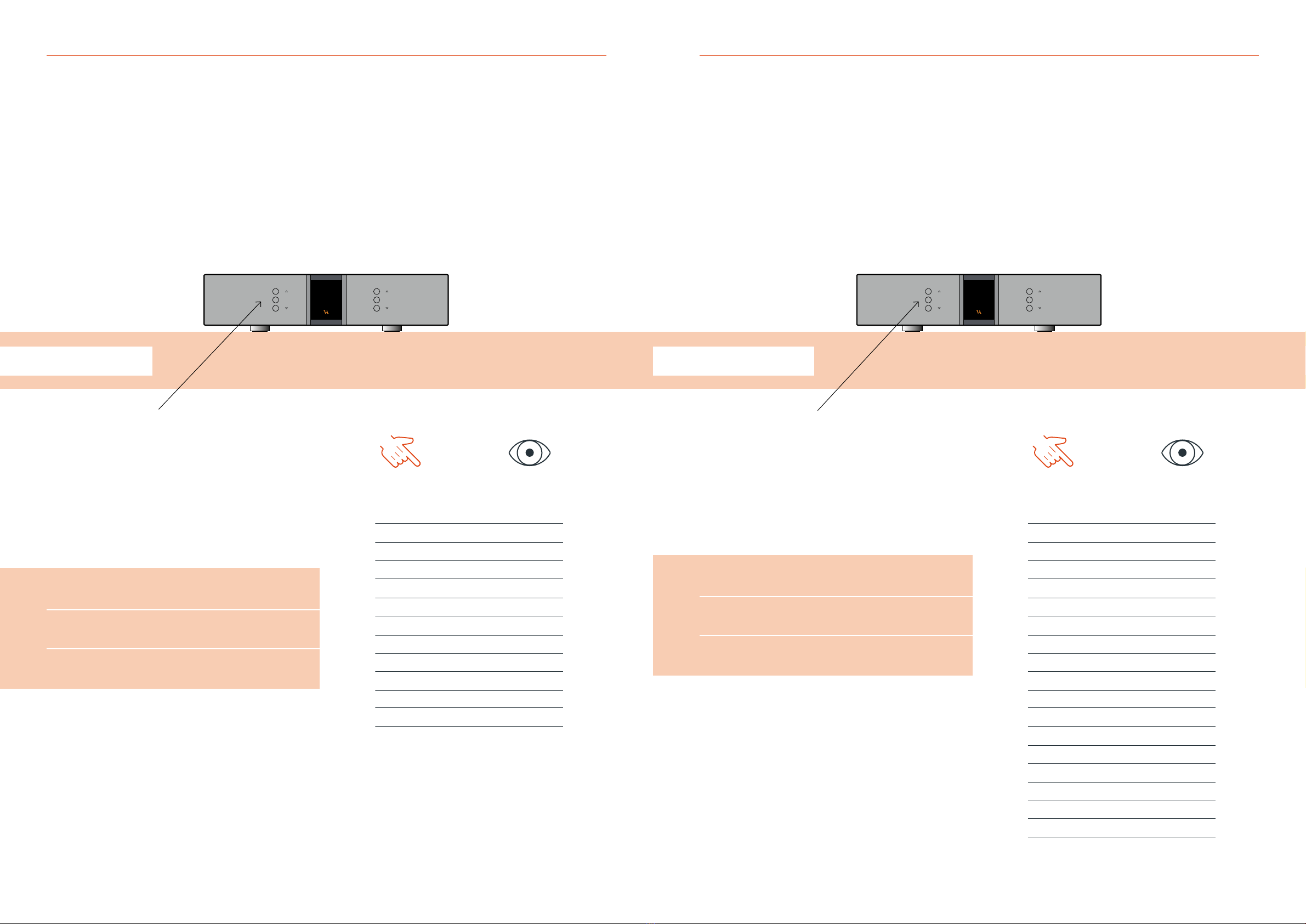
SELECT
INPUT
MENU
STANDBY
MUTE
7. EXAMPLES OF OPERATION
Changing offset volume for inputs
EXAMPLE 1
Changing oset volume for inputs
A specic volume oset on the RD-101 can be set on each individual
input, to accomodate for dierent output levels of dierent sources.
This can be used to reduce the dierence in output level, when
switching between inputs.
The oset value can be set from -12dB to +12dB.
Press the “MENU” button to enter menu mode.
Use the function buttons on the front of the unit to navigate to
SETUP - INPUTS and select the desired input.
1. r
Scroll forwards in the menu.
2. MENU/SELECT
Enter and exit submenus and select settings.
3. s
Scroll backwards in the menu.
Enter the OFFSET menu and navigate up or down in the oset steps
by utilising the function buttons until the desired oset is shown in
the display. Then press select and navigate to the exit menu point
and press select again.
The new oset setting has now been saved on the chosen input.
7. EXAMPLES OF OPERATION
YOU PRESS
MENU
SELECT
SELECT
SELECT
SELECT
SELECT
SELECT
YOU SEE
Line 1
< EXIT
SETUP >
< BACK
INPUTS >
< BACK
Streamer >
USB >
INPUT 2 >
< BACK
< EXIT
FIXED >
OFFSET >
0.0 dB
6.0 dB
OFFSET >
FIXED >
< EXIT
Line 1
30 | RD-101 Owner’s manual

32 | RD-101 Owner’s manual RD-101 Owner’s manual | 33
SELECT
INPUT
MENU
STANDBY
MUTE
SELECT
INPUT
MENU
STANDBY
MUTE
7. EXAMPLES OF OPERATION7. EXAMPLES OF OPERATION
Changing display brightness Changing initial volume step
EXAMPLE 3
Changing initial volume step
You can set the volume step that the RD-101 will initialise on,
every time it is taken out of standby mode.
Press the “MENU” button to enter menu mode.
Use the function buttons on the front of the unit to navigate
to SETUP - V.INIT.
1. r
Scroll forwards in the menu.
2. MENU/SELECT
Enter and exit submenus and select settings.
3. s
Scroll backwards in the menu.
Enter the V.INIT menu and navigate up or down in the volume steps
by utilising the function buttons until -35dB is shown in the display.
Then press select and navigate to the exit menu point and press
select again.
Next time you turn on the RD-101, it will initialise on volume
step -35dB.
EXAMPLE 2
Changing display brightness
The display on RD-101 can be set to dierent brightness levels
according to your preference.
Press the “MENU” button to enter menu mode.
Use the function buttons on the front of the unit to navigate
to SETUP - BRIGHT.
1. r
Scroll forwards in the menu.
2. MENU/SELECT
Enter and exit submenus and select settings.
3. s
Scroll backwards in the menu.
Enter the BRIGHT menu and navigate up or down in the brightness
steps by utilising the function buttons until the desired brightness
is shown in the display. Then press select and navigate to the exit
menu point and press select again.
The new brightness setting has now been saved.
YOU PRESS
MENU
SELECT
SELECT
SELECT
SELECT
YOU SEE
Line 1
< EXIT
SETUP >
< BACK
INPUTS >
BRIGHT >
LOGO >
V.INIT >
-40.0 dB
-35.0 dB
V.INIT >
LOGO >
BRIGHT >
INPUTS >
< BACK
< EXIT
Line 1
YOU PRESS
MENU
SELECT
SELECT
SELECT
SELECT
YOU SEE
Line 1
< EXIT
SETUP >
< BACK
INPUTS >
BRIGHT >
BRIGHT 1
BRIGHT 2
BRIGHT >
INPUTS >
< BACK
< EXIT
Line 1
34 | RD-101 Owner’s manual RD-101 Owner’s manual | 35
SELECT
INPUT
MENU
STANDBY
MUTE
SELECT
INPUT
MENU
STANDBY
MUTE
7. EXAMPLES OF OPERATION7. EXAMPLES OF OPERATION
Disabling inputs Changing input names
EXAMPLE 5
Example copy to be conrmed by client
The input display text of the RD-101 can be set on each individual
input.
Press the “MENU” button to enter menu mode.
Use the function buttons on the front of the unit to navigate
to SETUP - INPUTS and select the desired input.
1. r
Scroll forwards in the menu.
2. MENU/SELECT
Enter and exit submenus and select settings.
3. s
Scroll backwards in the menu.
Enter the TEXT menu and navigate up or down in the text choises
by utilising the function buttons until the desired text is shown in
the display. Then press select and navigate to the exit menu point
and press select again.
The new text has setting has now been saved on the chosen input.
EXAMPLE 4
Disabling inputs
Each individual input on the RD-101 can be disabled in the menu.
This will remove the input from being shown when changing inputs
in the normal operation mode.
Press the “MENU” button to enter menu mode.
Use the function buttons on the front of the unit to navigate
to SETUP - INPUTS and select the desired input.
1. r
Scroll forwards in the menu.
2. MENU/SELECT
Enter and exit submenus and select settings.
3. s
Scroll backwards in the menu.
Enter the USED menu and navigate up or down to choose the NOT
USED menu point by utilising the function buttons. Then press select
and navigate to the exit menu point and press select again.
The input has now been disabled and will not be shown in the menu
during normal operation.
YOU PRESS
MENU
SELECT
SELECT
SELECT
SELECT
SELECT
SELECT
YOU SEE
Line 1
< EXIT
SETUP >
< BACK
INPUTS >
< BACK
Streamer >
USB >
INPUT 2 >
< BACK
USED >
TEXT >
Line 1
SCD-025
TEXT >
USED >
BACK
< EXIT
SCD-025
YOU PRESS
MENU
SELECT
SELECT
SELECT
SELECT
YOU SEE
Line 1
< EXIT
SETUP >
< BACK
INPUTS >
BRIGHT >
BRIGHT 1
BRIGHT 2
BRIGHT >
INPUTS >
< BACK
< EXIT
Line 1

36 | RD-101 Owner’s manual RD-101 Owner’s manual | 37
SELECT
INPUT
MENU
STANDBY
MUTE
SELECT
INPUT
MENU
STANDBY
MUTE
7. EXAMPLES OF OPERATION7. EXAMPLES OF OPERATION
Setting fixed volume for inputs Configuring auto standby
EXAMPLE 7
Conguring auto standby
The RD-101 can be congured to automatically go into standby after
a set time period, after no buttons on the remote or front of the unit
having been pressed. Press the “MENU” button to enter menu mode.
Use the function buttons on the front of the unit to navigate to
SETUP - AutoStb.
1. r
Scroll forwards in the menu.
2. MENU/SELECT
Enter and exit submenus and select settings.
3. s
Scroll backwards in the menu.
Enter the AutoStb menu and navigate up to the desired auto standby
time, in this case 30 minutes. Then press select and navigate to the
exit menu point and press select again.
The new auto standby time setting has now been saved.
EXAMPLE 6
Setting xed volume for inputs
Each individual input on the RD-101 can be set to a xed volume
in the menu. The input is then locked to the set volume step and
can no longer be adjusted.
This function is used as the “home theater bypass” function,
if you have a surround processor that controls the volume.
Press the “MENU” button to enter menu mode.
Use the function buttons on the front of the unit to navigate
to SETUP - INPUTS and select the desired input.
1. r
Scroll forwards in the menu.
2. MENU/SELECT
Enter and exit submenus and select settings.
3. s
Scroll backwards in the menu.
Select FIXED - SET FIX and use the function buttons to set the x
to FIX ON, press select. Then select the ADJUST menu point and
use the function buttons to navigate to the desired volume step.
Press select and navigate to the exit menu point and press select again.
The input has now been set to a xed volume step and can no longer
be adjusted.
The x can always be turned o by repeating the steps above and set
the x to FIX OFF.
YOU PRESS
MENU
SELECT
SELECT
SELECT
SELECT
SELECT
SELECT
SELECT
SELECT
SELECT
YOU SEE
Line 1
< EXIT
SETUP >
< BACK
INPUTS >
< BACK
INPUT1 >
< BACK
< EXIT
FIXED >
< BACK
SET FIX >
FIX OFF
FIX ON
SET FIX >
ADJUST >
-40 dB
0.0 dB
ADJUST >
< EXIT
Line 1
YOU PRESS
MENU
SELECT
SELECT
SELECT
SELECT
YOU SEE
Line 1
< EXIT
SETUP >
< BACK
INPUTS >
BRIGHT >
LOGO >
V.INIT >
RESET >
AutoStb >
OFF
30 Min
AutoStb >
RESET >
V.INIT >
LOGO >
BRIGHT >
INPUTS >
< BACK
< EXIT
Line 1

38 | RD-101 Owner’s manual RD-101 Owner’s manual | 39
SELECT
INPUT
MENU
STANDBY
MUTE
7. EXAMPLES OF OPERATION7. EXAMPLES OF OPERATION
Restore factory settings
EXAMPLE 8
Restore factory settings
The RD-101 can be restored to it’s factory settings if needed.
Press the “MENU” button to enter menu mode.
Use the function buttons on the front of the unit to navigate
to SETUP - RESET.
1. r
Scroll forwards in the menu.
2. MENU/SELECT
Enter and exit submenus and select settings.
3. s
Scroll backwards in the menu.
Enter the RESET menu and navigate up or down utilising the function
buttons, until the displays show RES:YES. Then press select and the
RD-101 will reset itself and go into standby.
The product has now been reset to factory settings and put into
standby mode.
YOU PRESS
MENU
SELECT
SELECT
SELECT
YOU SEE
Line 1
< EXIT
SETUP >
< BACK
INPUTS >
BRIGHT >
LOGO >
V.INIT >
RESET >
RES: NO
RES: YES
RESETTIN
Other manuals for Reference Series
2
This manual suits for next models
1
Table of contents
Other Vitus Audio Media Converter manuals


