manuals.online logo
Brands
  1. Home
  2. •
  3. Brands
  4. •
  5. CTC Union
  6. •
  7. Media Converter
  8. •
  9. CTC Union IMC-100 User manual

CTC Union IMC-100 User manual

CTC Union Technologies Co., Ltd.
Far Eastern Vienna Technology Center
(Neihu Technology Park)
8F, No. 60 Zhouzi St., Neihu District, Taipei 114
Taiwan
T+886-2-26591021
F+886-2-26590237
E[email protected]
© 2014 CTC Union Technologies Co., Ltd.
All trademarks are the property of their respective owners.
Technical information in this document is subject to change without notice.
Introduction
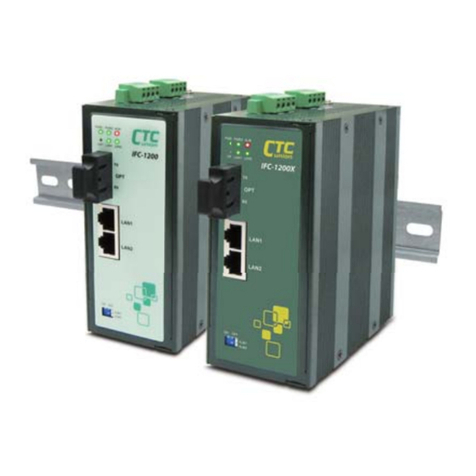
IMC-100(-E) are Fast Ethernet media converters that support
conversion between electrical 10/100Base-TX and optical
100Base-FX Ethernet. Housed in rugged DIN rail or wall
mountable enclosures, these converters are designed for harsh
environments, such as industrial networking and intelligent
transportation systems (ITS) and are also suitable for many
military and utility market applications where environmental
conditions exceed commercial product specifications. Standard
operating temperature range models (-10°C to 60°C) and wide
operating temperature range models (-40°C to 75°C) fulfill the
special needs of industrial automation applications.
Features
Redundant dual DC inputs 12/24/48VDC
IP30 rugged metal housing
Wide temperature range -40°C ~75°C (IMC-100-E)
Switch/converter mode setting
Industrial grade EMS, EMI, UL60950-1, EN50121-4,
EN61000-6-2, EN61000-6-4
Specifications
Ethernet Interface
Standards: IEEE802.3, 802.3u, 802.3x
Connector: RJ-45 (shielded)
Auto MDI/MDI-X
Speed: 10/100Base-TX (Auto/Forced by DIP)
Duplex: Full/Half (Auto/Forced by DIP)
Flow Control: 802.3x (enable by DIP)
Store & Forward Switch/Pass through converter (by DIP)
1024 MAC table (in switch mode)
MTU: 2046 bytes (switch)/9600 bytes (converter)
Link Fault Pass Through (LFP) (enable/disable by DIP)
Optical Interface
100Base-FX
Options for SC or ST connectors
Multimode (2km) 50/125um, 62.5/125um
Single mode (30km or 50km) 9/125um
Wavelength: 1310nm (S/M or M/M)
BiDi option (20km) for Single mode single fiber
Quick Installation Guide
IMC-100
IMC-100-E
Industrial Grade Fast Ethernet Media Converters
Specifications (cont.)
Power
Absolute Range: 9.6VDC~58VDC
Reverse Polarity Protection: Yes
Dual Power Inputs: Yes
Connector: Removable terminal block
Consumption: 2.9W
Mechanical
Water & Dust Proof: IP30 Protection
Dimensions: 106 mm (D) x 39 mm (W) x 142 mm (H)
Mounting: DIN-Rail, Wall Mount (Kits included)
Weight: 720 g (1.5 lb)
Environmental
Operating Temperature: -10°C~60°C (IMC-100)
-40°C~75°C (IMC-100-E)
Storage Temperature: -40°C~85°C
Humidity: 5%~95% (Non-condensing)
Certifications
EMC: CE
EMI (Electromagnetic Interference): FCC, FCC Part 15 Subpart
B Class A, CE EN55022 Class A
Railway Traffic: EN50121-4
Immunity for Heavy Industrial Environment: EN61000-6-2
Emission for Heavy Industrial Environment: EN61000-6-4
EMS (Electromagnetic Susceptibility) Protection Level:
EN61000-4-2 (ESD) Level 3, Criteria B
EN61000-4-3 (RS) Level 3, Criteria A
EN61000-4-4 (Burst) Level 3, Criteria A
EN61000-4-5 (Surge) Level 3, Criteria B
EN61000-4-6 (CS) Level 3, Criteria A
EN61000-4-8 (PFMF, Magnetic Field) Field Strength:
300A/m, Criteria A
Safety: UL60950-1
Shock: EN60068-2-27
Freefall: EN60068-2-32
Vibration: EN60068-2-6
MTBF: 852,727 hours (MIL-HDBK-217)
[email protected]
To download this QIG or a more complete user manual, please visit
http://www.ctcu.com/Industrial/
V1.5
- 2 -
- 1 -
www.ctcu.com
Connectors
Figure 1. Front Panel
FIBER & LAN Connection
IMC-100(-E) has fixed optical transceiver options for connector
types of ST or SC. The LAN connection uses a shielded RJ-45 which
supports Auto MDI/MDI-X. Configuration settings are
accomplished via a 6-pole DIP (dual inline package) switch. Please
see the page 5 for the settings of the operation mode switch.
Power & Alarm
Power
There are input connectors for two power sources on the
removable terminal block. Only one power source is required for
normal operation. The second power source input may be
provided for redundancy.
Operation Mode Switch
IMC-100(-E) uses a 6-pole DIP switch for configuration.
DIP
No.
Status
Function
Description
1
OFF *
Auto
Nway auto-negotiation of the TP port.
ON
Force
Manual forced mode. Before
configuring the speed and duplex
settings, this DIP switch must be ON.
2
OFF *
100
Force TP port speed to 100M (DIP No.
1 must be ON).
ON
10
Force TP port speed to 10M (DIP No. 1
must be ON).
3
OFF *
Full
Force TP port to Full Duplex (DIP No. 1
must be ON).
ON
Half
Force TP port to Half Duplex (DIP No. 1
must be ON).
4
OFF *
Disable LFP
Disable LFP (Link Fault Pass through).
ON
Enable LFP
LFP (Link Fault Pass through) allows a
link condition to be passed from fiber
to TP or from TP to fiber. LFP is only
available when the converter is set to
'Switch' mode (DIP No. 6 is OFF) and
'Auto' negotiation (DIP No. 1 is OFF).
5
OFF *
Disable Flow
Control
Disable flow control.
ON
Enable Flow
Control
Enable flow control.
6
OFF *
Switch Mode
In Switch mode, the device acts as a
store & forward device supporting
MAC learning and filtering with MTU
of 2046 bytes.
ON
Pass
Through
Mode
The device acts as pure 'converter'
that the internal switch is bypassed,
enabling low latency and jumbo frame
support. Do not enable LFP in this
mode or fiber may not link.
NOTE 1: By default, all DIP switches are set to OFF (marked with *).
NOTE 2: After changing the DIP switch setting, you must restart the device to
activate the setting.
Alarm Relay Contact
The Alarm is one electrical relay that can be wired into an alarm
circuit and is triggered in the event of either link loss for optical or
electrical or both. From the common pin (COM), the relay can be
connected as Normally Open (NO) or Normally Closed (NC). When
an alarm occurs NO-to-COM circuit closes and the COM-to-NC
circuit opens. See Figure 3 and 4 for normal and fault illustration
in each alarm relay type. Please note that the alarm relay contact
can only support 1A current at 24VDC. Do not apply voltage and
current that exceed these specifications.
LED Indicators
LED
Color
Definition
PWR1/
PWR2
Green
Power is connected and active at the
PWR1/PWR2 input terminal connection.
Off
Power is not connected.
Fault
Red
Lit if the fiber or TP have any fault
condition.
Off
No fiber or TP faults.
Fiber
Green
Fiber port has optical link.
Blinking
Blinking when there is data traffic.
Off
No optical link.
100
Amber
LAN connected speed is 100M.
Off
LAN connected speed is 10M.
LAN
Green
LAN port has a link.
Blinking
Blinking when there is Ethernet traffic.
Off
LAN port does not have a link.
Installation
IMC-100(-E) comes with both wall mount and DIN rail hardware
brackets. When installing the DIN rail bracket, be sure to correctly
align the orientation pin.
Figure 6. DIN Rail Figure 7. Wall Mount
IMC-100(-E) with DIN Rail bracket has a steel spring in the
upper rail of the bracket. This spring is compressed for mounting
and un-mounting by applying downward force.
Figure 8. Mounting Figure 9.Un-mounting
Application
- 3 -
- 4 -
1 2 3 4 5 6
- 6 -
Figure 2. Terminal block
Figure 10. IMC-100(-E) Application
Figure 5. DIP Switch
Figure 3. Alarm Relay for NO (Normally Open) Type
Fault
Normal
COM
NO
COM
NO
Figure 4. Alarm Relay for NC (Normally Closed) Type
Normal
Fault
COM
NC
COM
NC
- 5 -
www.ctcu.com

This manual suits for next models

1

Other CTC Union Media Converter manuals

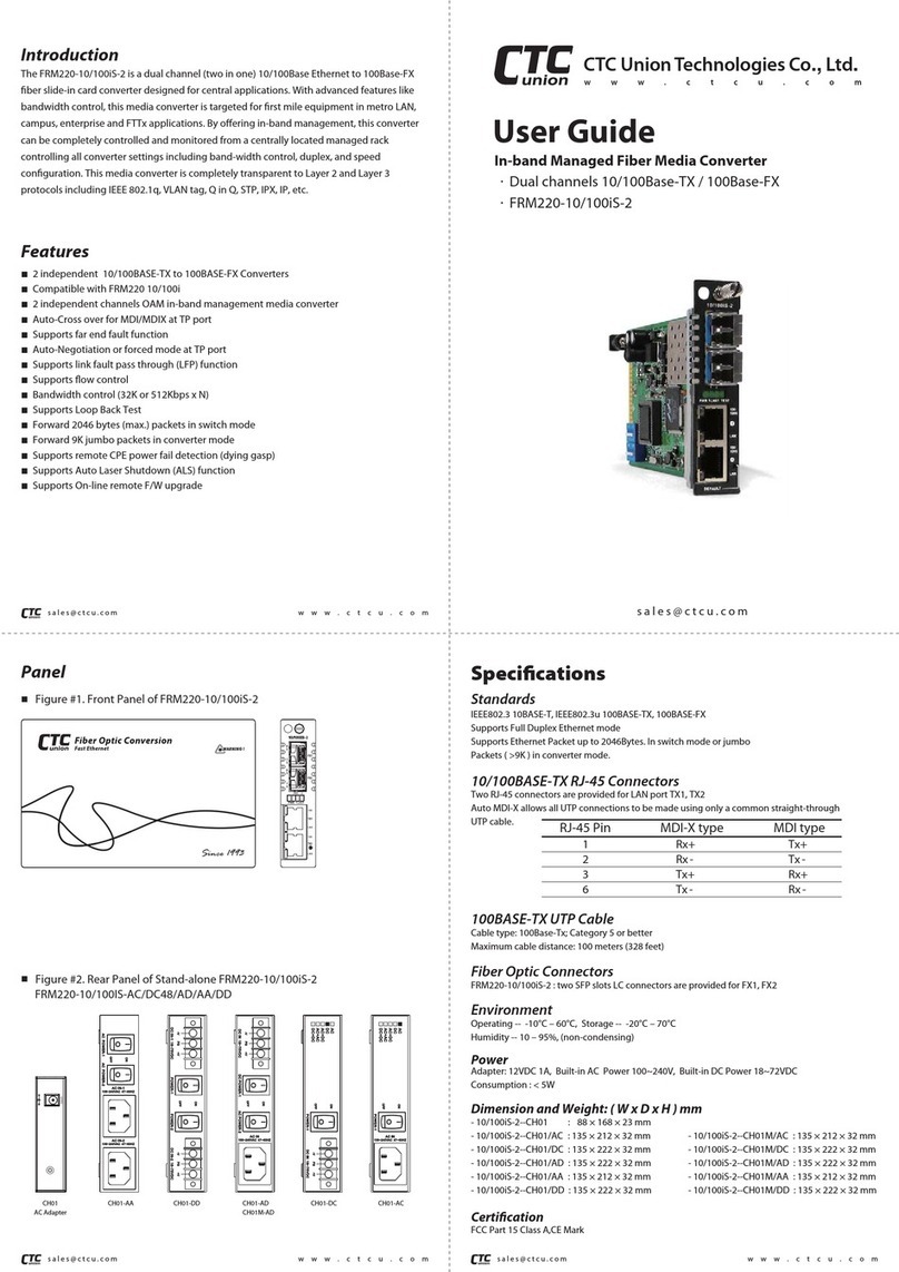
CTC Union FRM220-NMC User manual

CTC Union

CTC Union FRM220-NMC User manual

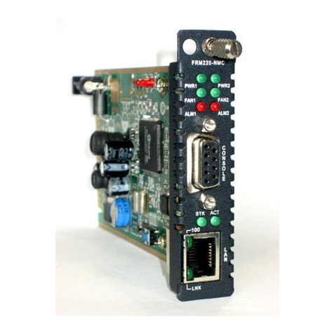
CTC Union FRM220A Manual

CTC Union

CTC Union FRM220A Manual

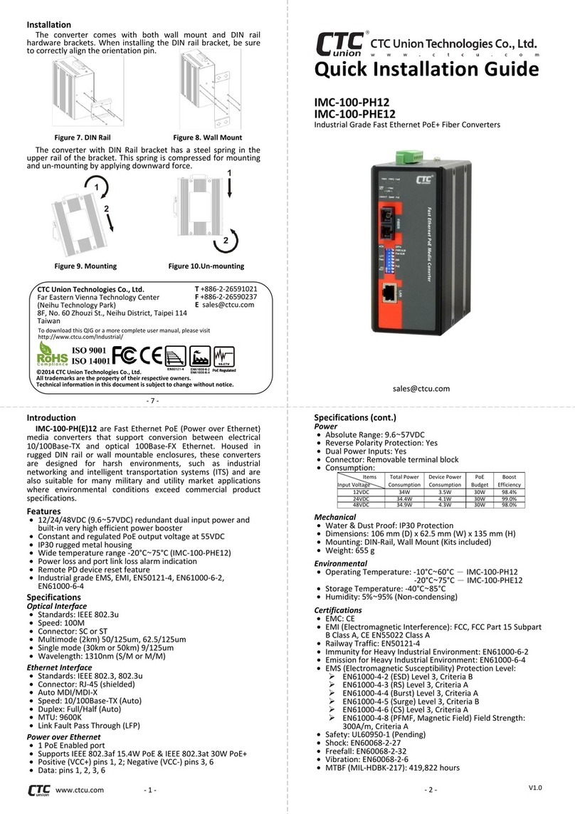
CTC Union FRM220-FXO User manual

CTC Union

CTC Union FRM220-FXO User manual

CTC Union FRM220-FXO-4 User manual

CTC Union

CTC Union FRM220-FXO-4 User manual

CTC Union FMC-1001S User manual

CTC Union

CTC Union FMC-1001S User manual

CTC Union FMC-10/100LF User manual

CTC Union

CTC Union FMC-10/100LF User manual

CTC Union FMC-1000S User manual

CTC Union

CTC Union FMC-1000S User manual

CTC Union IMC-1000C User manual

CTC Union

CTC Union IMC-1000C User manual

CTC Union FRM220-10 User manual

CTC Union

CTC Union FRM220-10 User manual

CTC Union FRM220-1000MS User manual

CTC Union

CTC Union FRM220-1000MS User manual

CTC Union FRM220-10/100i(S)-2E-DC12 User manual

CTC Union

CTC Union FRM220-10/100i(S)-2E-DC12 User manual

CTC Union DVS-8504E User manual

CTC Union

CTC Union DVS-8504E User manual

CTC Union FMC-2000MS User manual

CTC Union

CTC Union FMC-2000MS User manual

CTC Union IFC-Serial User manual

CTC Union

CTC Union IFC-Serial User manual

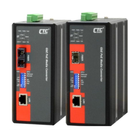
CTC Union IMC-100-E User manual

CTC Union

CTC Union IMC-100-E User manual

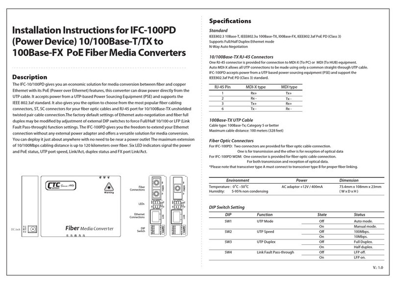
CTC Union IFC-100PD User manual

CTC Union

CTC Union IFC-100PD User manual

CTC Union FMC-10/100 User manual

CTC Union

CTC Union FMC-10/100 User manual

CTC Union FRM220-10/100 User manual

CTC Union

CTC Union FRM220-10/100 User manual

CTC Union FRM220-2000MS User manual

CTC Union

CTC Union FRM220-2000MS User manual

CTC Union FIB-232A-ST User manual

CTC Union

CTC Union FIB-232A-ST User manual

CTC Union IMC-1000-PH12 User manual

CTC Union

CTC Union IMC-1000-PH12 User manual

CTC Union IMC-1000M-PH12 User manual

CTC Union

CTC Union IMC-1000M-PH12 User manual

CTC Union FRM220 User manual

CTC Union

CTC Union FRM220 User manual

CTC Union IMC-100-PH12 User manual

CTC Union

CTC Union IMC-100-PH12 User manual

Popular Media Converter manuals by other brands

Delta Electronics Delphi F48SA datasheet

Delta Electronics

Delta Electronics Delphi F48SA datasheet

Konig CMP-USBVG5 manual

Konig

Konig CMP-USBVG5 manual

Miteq 9800 Series Technical notes

Miteq

Miteq 9800 Series Technical notes

Sendix PROFI BUS Singleturn 5858 Series Technical manual

Sendix

Sendix PROFI BUS Singleturn 5858 Series Technical manual

TR-Electronic CMV582M-4096/4096 PB 36ZB10FL Assembly instructions

TR-Electronic

TR-Electronic CMV582M-4096/4096 PB 36ZB10FL Assembly instructions

Axis Q7436 user manual

Axis

Axis Q7436 user manual

Liberty IPEX5100 Series install guide

Liberty

Liberty IPEX5100 Series install guide

ORiNG ITGMC-111GP+ Quick installation guide

ORiNG

ORiNG ITGMC-111GP+ Quick installation guide

Sony TDM-NC1 - Wi-fi Client For Streaming Music Specifications

Sony

Sony TDM-NC1 - Wi-fi Client For Streaming Music Specifications

Moxa Technologies TCF-142-RM Series Hardware installation guide

Moxa Technologies

Moxa Technologies TCF-142-RM Series Hardware installation guide

EtherWAN EL1032T Series installation guide

EtherWAN

EtherWAN EL1032T Series installation guide

Sony TDM-NC1 - Wi-fi Client For Streaming Music operating instructions

Sony

Sony TDM-NC1 - Wi-fi Client For Streaming Music operating instructions

Resi E4300 Setup instructions

Resi

Resi E4300 Setup instructions

Phoenix Contact GW PN/DP 1E/1DB9 user manual

Phoenix Contact

Phoenix Contact GW PN/DP 1E/1DB9 user manual

SIIG AV-GM04R3-S1-TX manual

SIIG

SIIG AV-GM04R3-S1-TX manual

Crestron DM-NVX-E30 product manual

Crestron

Crestron DM-NVX-E30 product manual

eks e-light U3 Description and manual

eks

eks e-light U3 Description and manual

Moxa Technologies TCF-142-M-ST Quick installation guide

Moxa Technologies

Moxa Technologies TCF-142-M-ST Quick installation guide

manuals.online logo
manuals.online logoBrands
  • About & Mission
  • Contact us
  • Privacy Policy
  • Terms and Conditions

Copyright 2025 Manuals.Online. All Rights Reserved.