Vivotek FE8391-V User manual

Quick Installation Guide
360° Surround View • 10M IR • PoE
All specications are subject to change without notice.
Copyright 2015 VIVOTEK INC. All rights reserved.
c
P/N:625028801G Rev.: 1.1
FE8391-V Fisheye
Network Camera
English 繁中 日本語 Español Português
簡中 Français Deutsch Italiano Türkçe Polski Русский Česky Svenska
Dansk
Dutch
Indonesia
VIVOTEK Europe
Randstad 22-133, 1316BW Almere, The Netherlands

EN - 1
English
Warning Before Installation
Power off the Network Camera as soon as
smoke or unusual odors are detected.
Do not place the Network Camera on
unsteady surfaces.
Do not insert sharp or tiny objects into the
Network Camera.
Refer to your user's manual for the
operating temperature.
Do not touch the Network Camera
during a lightning storm.
Do not drop the Network Camera.
Package Contents
1
5
1
0
0
0
0
2
1
0
G
FE8391-V Mounting Plate / Screwdriver
Alignment Stickers Screws / Desiccant Bag /
Double-sided Tape / Rubber Seal
Plug / Rubber Washer
Quick Installation Guide Software CD
Power & I/O Cables
For Mounting Plate For Camera Base
(Sold Separately in US & Canada)

EN - 2
Physical Description
2
Inner View
Header (J7) Contacts (A)
Lens
Header (J6)
Ethernet 10/100 RJ45 Socket
i
Align (B) to (A) when
attaching the dome cover
MicroSD/SDHC/SDXC Card Slot
Reset Button
Status LEDs
Contacts for IR units (B)

EN - 3
English
083236
Outer View
Built-in Microphone
IP66-rated Vandal-proof
Dome Cover
IMPORTANT:
Record the MAC address under the
camera base before installing the
camera.
Hardware Installation
3
Rubber Stopper on the hole for
Power & IO Cables
Tamper-proof Screw
Rubber Seal Plug on the hole
for RJ45 Ethernet Cable
First, use the supplied screwdriver to loosen the four screws and detach the dome cover from the
camera base. Then, follow the steps below to install the camera to either a ceiling or a wall.
Remove the stoppers and route cables through the
openings.
IR lights hidden beneath panel

EN - 4
RJ45 Cable Dimension (unit: mm)
Assembly Steps
1. Drill a hole on the rubber seal plug and in-
sert an Ethernet cable through the opening.
2. Strip part of the sheath from the Ethernet
cable.
Recommended cable gauge: (0.51 cm)
Connecting RJ45 Ethernet Cable
Rubber Seal
Plug
1
2
Connecting DC Power Cable
1. Add the supplied rubber washer to the cable as
shown in the picture.
2. Feed the cable from the bottom of the camera
and tighten the plastic base for waterproong.
1
2
3. You will need an RJ45 crimping tool to
attach the Ethernet wires to a connec-
tor. When done, connect the cable to
the camera’s Ethernet RJ45 socket.
o
O
g
B
b
G
br
BR
1
2
3
4
5
6
7
8
3
44. Feed the Ethernet cable from the bottom of the
camera and through the hole. Attach the rubber seal
plug for water proong.
o: white/orange stripe
O: orange solid
g: white/green stripe
B: blue solid
b: white/blue stripe
G: green solid
br: white/brown stripe
BR: brown solid
Connect the supplied power & IO cables if your
switch does not support PoE.
NOTE:

EN - 5
English
Ceiling/Wall Mount without Mounting Plate
(Choose this mounting type if you want to feed the cables form the bottom of
the camera)
NOTE:
Header (J7)
Header (J6)
12
3
8
9
4
5
6
1. Attach the supplied alignment sticker for camera base to the ceiling/wall.
2. Using the three circles on the sticker, drill three pilot holes into the ceiling. Then hammer the
three supplied plastic anchors into the holes.
3. Drill a cable hole on the ceiling/wall, and feed the cables through the hole.
4. Connect the Ethernet cable to the socket.
5. Connect the two white header connectors to the J6 and J7 connectors.
6. Secure the camera base to the ceiling/wall with three supplied screws.
7. You will nd a dessicant bag attached to the camera. Replace the dessicant bag included in the
camera with the one shipped within the accessory bag.
8. Attach the dome cover.
9. Secure the four screws with the supplied stardriver. Make sure all camera parts are securely in-
stalled.
Arrange the cables neatly to avoid getting in
the way when the dome cover is attached.
7

EN - 6
Ceiling/Wall Mount with Mounting Plate
(Choose this mounting type if you would like to feed the cables form the side)
1
2
3
4
7
9
10
1. Attach the supplied alignment sticker for the supplied mounting plate to the ceiling/wall.
2. Using the three circles on the sticker, drill three holes into the ceiling. Then hammer the three
supplied plastic anchors into the holes.
3. Arrange and feed the cables through the side of the mounting plate.
4. Secure the mounting plate to the ceiling/wall with three supplied screws.
5. Connect the Ethernet cable to the socket.
6. Connect two white headers to the J6 and J7 connectors.
7. Attach the camera base to the mounting plate and turn counter-clockwise as shown below.
Then secure the supplied screws to x the camera base.
8. You will nd a dessicant bag attached to the camera. Replace the dessicant bag with the one
shipped within the accessory bag.
9. Attach the dome cover.
10. Secure the four screws with the supplied stardriver. Make sure all camera parts are securely
installed.
8

EN - 7
English
1. Connect RJ45 Ethernet cable to a switch.
2. Connect the power cable from the Network Camera to a power outlet.
3. If you have external devices such as sensors and alarms, make the connection from the general I/
O terminal block.
General Connection (without PoE)
Network Deployment
4
POWER C
OLLIS
ION
LINK
RECEIVE
PARTITION
12345
+3V3
DO
D1
GND
1
2
3
General I/O Terminal Block
Power Cord Socket (Black)
Microphone In (Pink)
Audio Out (Green)
+3V3 : Power, 3.3V DC
DO : Digital Output
DI : Digital Input
GND : Ground
You may also use the diagonal holes on the mounting plate,
marked as A, B, or C, to install the camera to a standard 4 in.
junction box.
IMPORTANT:
1. When IR lights are on in the night, the total power consumption is 23W.
2. If DC power is preferred, it should comply with: O/P: 12VDC, 2A min., L.P.S. per IEC 60950-1.

EN - 8
Use a PoE power injector (optional) to connect between the Network Camera and a non-PoE switch.
When using a non-PoE switch
Power over Ethernet (PoE)
The Network Camera is PoE-compliant, allowing transmission of power and data via a single Ether-
net cable. Follow the below illustration to connect the Network Camera to a PoE-enabled switch via
Ethernet cable.
When using a PoE-enabled switch
POWER C
OLLIS
ION
LINK
RECEIVE
PARTITION
12345
PoE Switch
PoE Power Injector
(optional)
Non-PoE Switch
NOTE:
1. This equipment is only to be connected to PoE networks without routing to outside plants.
2. For PoE input, use only UL listed I.T.E. with PoE output.
IMPORTANT:
When IR lights are on in the night, the total power consumption is 23W. An 802.3at PoE PSE, e.g.,
PoE switch, is required.

EN - 9
English
1. Install “Installation Wizard 2” from the Software Utility directory on the software CD.
2. The program will conduct an analysis of your network environment. After your network is
analyzed, please click on the “Next” button to continue the program.
3. The program will search for VIVOTEK Video Receivers, Video Servers, and Network Cameras on
the same LAN.
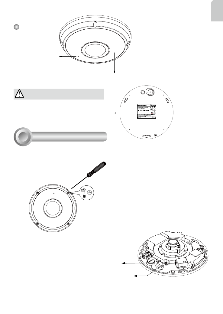
4. After a brief search, the main installer window will pop up. Double-click on the MAC address that
matches the one printed on the camera label or the serial number on the package box label to
open a browser management session with the Network Camera.
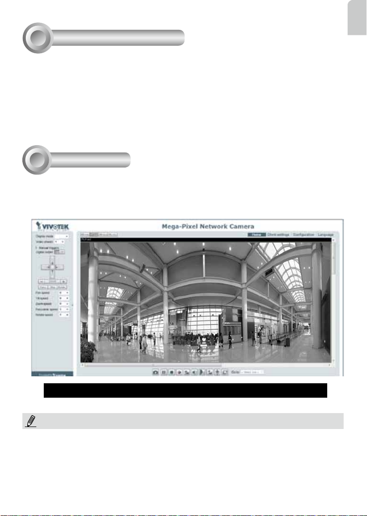
Assigning an IP Address
5
1. A browser session with the Network Camera should prompt as shown below.
2. You should be able to see live video from your camera. You may also install the 32-channel record-
ing software from the software CD in a deployment consisting of multiple cameras. For its installa-
tion details, please refer to its related documents.
Ready to Use
6
For further setup, please refer to the user's manual on the software CD.
1P
NOTE:
If you encounter problems with displaying live view or the onscreen plug-in control, you may try to
manually remove the plug-ins that might have been installed on your computer. Remove the following
folder: C:\Program Files (x86)\Camera Stream Controller.

AR - 168
What Is Covered : This warranty covers any hardware defects in materials or
workmanship, with the exceptions stated below.
How Long Coverage Lasts: This warranty lasts for THIRTY-SIX MONTHS from
the date of purchase by the original end-user customer.
What Is Not Covered : This warranty does not cover cosmetic damage or any
other damage or defect caused by abuse, misuse, neglect, use in violation of
instructions, repair by an unauthorized third part y, or an act of God. Also, if serial
numbers have been altered, defaced, or removed. Furthe r, consequential and
incidental damages are not recoverable under this warranty.
What VIVOTEK Will Do: VIVOTEK will, in our sole discretion, repair or replace
any product that proves to be defective in material or workmanship. Any repair or
replaced part of the product will receive a THREE-MONTH warranty extension.
How To Get Service: Contact our authorized distributors in your region. Please
check our website (www .vivotek.com) for the information of an authorized
distributor near you.
Your Rights: SOME S TATES DO NO T ALLOW EXCLUSION OR LIMIT ATION
OF CONSEQUENTIA L OR INCIDENTAL DAMAGES, SO THE ABOVE EXCLU-
SION OR LIMI TATION MA Y NOT APPLY TO YOU. THIS W ARRANT Y GIVES
YOU SPECIFIC LEGAL RIGHTS, AND YOU MAY ALSO HAVE OTHER RIGHTS
WHICH VARY FROM STATE TO STATE.
1. Proof of the date of purchase is required. In the event you can not render such
document, warranty will commence from the date of manufacture.
2. Cosmetic damage will only be covered by this warranty if such damage has
been existed at the time of purchase.
VIVOTEK INC.
6F, No. 192, Lien-Cheng Rd., Chung-Ho,
Taipei County, Taiwan.
www.vivotek.com

Quick Installation Guide
9MP • 360° Surround View • 10M IR • PoE
All specications are subject to change without notice.
Copyright 2015 VIVOTEK INC. All rights reserved.
c
P/N:625028801G Rev.: 1.1
FE8391-V Fixed Dome
Network Camera
English 繁中 日本語 Español Português
簡中 Français Deutsch Italiano Türkçe Polski Русский Česky Svenska
Dansk
Dutch
Indonesia
VIVOTEK Europe
Randstad 22-133, 1316BW Almere, The Netherlands
T:+31(0)36-5298-434 E:[email protected]
Table of contents
Other Vivotek Network Camera manuals

Vivotek
Vivotek IP8173H User manual

Vivotek
Vivotek IP8161 User manual

Vivotek
Vivotek SF8174 User manual

Vivotek
Vivotek TB53B6 SERIES User manual

Vivotek
Vivotek SD8362E User manual

Vivotek
Vivotek FD8166 User manual

Vivotek
Vivotek IP9171-HP User manual

Vivotek
Vivotek FD9165-HT User manual

Vivotek
Vivotek PZ8111 User manual

Vivotek
Vivotek IP8161 User manual