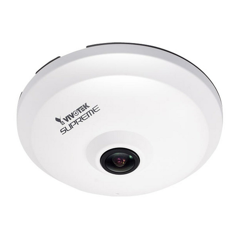
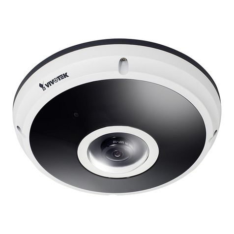
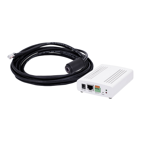
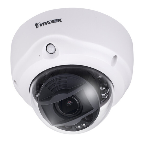
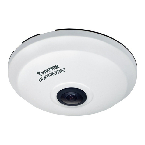
Vivotek FE9181-H User manual

Quick Installation Guide
5MP • 360° Surround View • H.265 • PoE
All specications are subject to change without notice.
Copyright 2015 VIVOTEK INC. All rights reserved.
c
P/N:625033400G Rev.: 1.0
FE9181-H Fixed Dome
Network Camera
English 繁中 日本語 Español Português
簡中 Français Deutsch Italiano Türkçe Polski Русский Česky Svenska
Dansk
Dutch
Indonesia
VIVOTEK Europe
Randstad 22-133, 1316BW Almere, The Netherlands

EN - 1
English
Warning Before Installation
Power off the Network Camera
as soon as smoke or unusual
odors are detected.
Do not place the Network
Camera on unsteady surfaces.
Do not insert sharp or tiny
objects into the Network
Camera.
Refer to your user's manual
for the operating temperature.
Do not touch the Network
Camera during a lightning
storm.
Do not drop the Network
Camera.
Package Contents
1
D
r
i
l
l
h
o
l
e
D
r
i
l
l
h
o
l
e
5
1
0
0
0
0
2
1
0
G
FE9181-H
Alignment Sticker
Screws / Anchors / Cable tie
Quick Installation Guide
Software CD
Power & I/O Cables
(Sold Separately in US & Canada)

EN - 2
Physical Description
2
Inner View
Header (J7)
Spring Contacts
(A)
Lens Contacts for Internal Microphone
(B)
Header (J12)
Ethernet 10/100 RJ45 Socket
MicroSD/SDHC/SDXC Card Slot
Reset Button
Status LEDs
Cabling Cutout

EN - 3
English
Outer View
Built-in Microphone
Dome Cover
IMPORTANT:
Record the MAC address under the
camera base before installing the
camera.
Hardware Installation
3
Release button
First, open the dome cover by pressing the release button. You may squeeze the opposite edge of
the dome cover if the dome cover does not come off easily. Then, follow the steps below to install the
camera to either a ceiling or a wall.
083236
4
If you plan to route cables from the side of camera, re-
move the rubber slide cover from the dome cover.
Slide cover

EN - 4
Connect the supplied power & IO cables if your
switch does not support PoE. Connect the white
header connectors to J12 and J7 on the camera.
Power and IO
cables
Connecting Ethernet Cable
& the Power and IO Cable
Connecting Cables
If you need to route cables through the side opening, proceed with
the following:
1. Connect the Ethernet and the Power & IO cables. The Ethernet cable
is user-supplied.
2. Use an included cable tie to secure the Ethernet and IO cable to the base plate. Insert the cable
tie through the vertical mounting tab located on the edge of the cabling cutout.
3. Make a clearance between cables and the vertical mounting tab. Arrange the cables neatly to
avoid getting in the way when the dome cover is attached.
4. Cut the extra length from the cable tie.
It is recommended to remove the strain relief boot if your Ethernet cable
comes with one.
J12
J7
Ethernet
Power & IO Cable
Make a clearance
between cables and
the vertical tab
Strain relief boot
If you route cables through a drill hole on
a wall/ceiling, simply route cables through
the cabling cutout.

EN - 5
English
D
r
i
l
l
h
o
l
e
D
r
i
l
l
h
o
l
e
D
r
i
l
l
h
o
l
e
D
r
i
l
l
h
o
l
e
D
r
i
l
l
h
o
l
e
D
r
i
l
l
h
o
l
e
Ceiling or Wall Mount
12
3
4
1. Attach the supplied alignment sticker for the camera base to the a ceiling or wall.
2. Using the circles on the sticker, drill pilot holes into the ceiling. Then hammer the supplied plastic
anchors into the holes.
3. (Optional) Drill a cable hole on the ceiling/wall, and feed the cables through the hole.
4. Secure the camera base to the ceiling/wall with the supplied screws.
You may also install the camera to a U.S. standard 4 in. junction box.
You can align the camera’s curved slots with the mounting holes on
a junction box. Use diagonal mounting positions on the camera to
match those on a junction box.
NOTE:

EN - 6
Install the plastic dome cover by aligning the snap-
t tabs on the dome cover with the slotted tabs on the
camera base. Install the dome cover by pressing it
evenly to the camera base.
Make sure the dome cover and the base plate are
ush-aligned before pressing down. The dome cover is
secured using a snap-t mechanism.
Attach the Dome Cover
Snap-t tabs
Dome cover
Slotted tabs

EN - 7
English
1. Connect RJ45 Ethernet cable to a switch.
2. Connect the power cable from the Network Camera to a power outlet.
3. If you have external devices such as sensors and alarms, make the connection from the general
I/O terminal block.
General Connection (without PoE)
Network Deployment
4
POWER C
OLLIS
ION
LINK
RECEIVE
PARTITION
12345
+3V3
DO
D1
GND
1
2
3
General I/O Terminal Block
Power Cord Socket (Black)
Microphone In (Pink)
Audio Out (Green)
+3V3: Power, 3.3V DC
DO: Digital Output
D I: Digital Input
GND: Ground
NOTE:
If DC power is preferred, it should comply with: O/P:
12VDC, 1.5Amin., L.P.S. per IEC 60950-1.

EN - 8
Use a PoE power injector (optional) to connect between the Network Camera and a non-PoE switch.
When using a non-PoE switch
Power over Ethernet (PoE)
The Network Camera is PoE-compliant, allowing transmission of power and data via a single Ether-
net cable. Follow the below illustration to connect the Network Camera to a PoE-enabled switch via
Ethernet cable.
When using a PoE-enabled switch
POWER C
OLLIS
ION
LINK
RECEIVE
PARTITION
12345
PoE Switch
POWER C
OLLIS
ION
LINK
RECEIVE
PARTITION
12345
PoE Power Injector
(optional)
Non-PoE Switch
NOTE:
1. This equipment is only to be connected to PoE networks
without routing to outside plants.
2. For PoE input, use only UL listed I.T.E. with PoE output.

EN - 9
English
1. Install “Installation Wizard 2” from the Software Utility directory on the software CD.
2. The program will conduct an analysis of your network environment. After your network is
analyzed, please click on the “Next” button to continue the program.
3. The program will search for VIVOTEK Video Receivers, Video Servers, and Network Cameras
on the same LAN.
4. After a brief search, the main installer window will pop up. Double-click on the MAC address
that matches the one printed on the camera label or the serial number on the package box label
to open a browser management session with the Network Camera.
Assigning an IP Address
5
1. A browser session with the Network Camera should prompt as shown below.
2. You should be able to see live video from your camera. You may also install the 32-channel
recording software from the software CD in a deployment consisting of multiple cameras. For its
installation details, please refer to its related documents.
Ready to Use
6
For further setup, please refer to the user's manual on the software CD.
NOTE:
If you encounter problems with displaying live view or the onscreen plug-in control, you may try to
remove the plug-ins that might have been installed on your computer. Remove the following folder: C:\
Program Files (x86)\Camera Stream Controller\.

TC - 10
安裝前應注意事項
如果發現網路攝影機出現煙霧或聞
到異味時,請立即關閉電源。
請勿將網路攝影機擺放在不穩定的
物 體 上。
請 勿 將 任 何 物 件 插 入 網 路 攝 影 機,
例 如 細 針。
有關操作時的溫度,請參閱使用者說
明書。
閃 電 時,請 勿 碰 觸 網 路 攝 影 機。
請勿讓網路攝影機掉落地面。
檢查包裝內容物
1
5
1
0
0
0
0
2
1
0
G
FE9181-H
校準貼紙
螺絲/壁虎/束線帶
快速安裝手冊
軟體光碟
電源及I/O纜線
D
r
i
l
l
h
o
l
e
D
r
i
l
l
h
o
l
e

TC - 11
中文 (繁體)
實體外觀說明
2
內視圖
排針(J7)
彈簧接腳(A)
鏡頭 內部麥克風的接腳(B)
排針(J12)
乙太網路10/100 RJ45插槽座
MicroSD/SDHC/SDXC卡插槽 重設按鈕
狀態LED
電纜佈線孔

TC - 12
外觀
內建麥克風
半球型外殼
在架設攝影機之前,請務必先記下網路攝影機的
M A C 位 址。
重要事項:
083236
4
硬體架設
3
鬆開按鈕
首先,請按下鬆開按鈕開啟半球型外殼。如果半球型外殼不好拆下,您可以推擠半球型外殼另一側的邊緣。
接著依照下方步驟執行,即可將攝影機安裝在天花板或牆壁上。
如果您計畫從攝影機的側邊拉線,請取下半球型外殼上的橡膠滑
蓋。
滑蓋

TC - 13
中文 (繁體)
J12
J7
如果您的交換器不支援乙太網路供電(PoE),請連接隨附
的電源及IO纜線。將白色的排針連接器連接至攝影機上
的 J 1 2 及 J 7。
電源及I/O纜線
連接乙太網路線以及電源線和
IO纜線
連接纜線
如果您需要透過側邊開口拉線,請依下列步驟執行:
1. 連接乙太網路線以及電源線和IO纜線。乙太網路線由使用者提供。
2. 使用隨附的束線帶將乙太網路線和IO纜線綁在底座板上。將束線帶穿過位於電纜佈線口邊緣的垂直安
裝 固 定 片。
3. 在纜線及垂直安裝固定片之間保留空隙。將纜線排列整齊,以免在安裝上蓋時造成阻礙。
4. 剪下多餘的束線帶。
建議使用不含電源線扣套的乙太網路線。若您的纜線有線扣套,可以將它拆
除。
如果要透過牆壁/天花板上的鑽孔拉線,只要
透 過 纜 線 佈 線 孔 拉 線 即 可。
乙太網路
電源及I/O纜線
在纜線及垂直固定
片之間保留空隙
電源線扣套

TC - 14
D
r
i
l
l
h
o
l
e
D
r
i
l
l
h
o
l
e
D
r
i
l
l
h
o
l
e
D
r
i
l
l
h
o
l
e
D
r
i
l
l
h
o
l
e
D
r
i
l
l
h
o
l
e
天花板或牆壁安裝
12
3
4
1. 將隨附的校準貼紙貼在天花板/牆壁上。
2. 利用貼紙上的圓圈標誌,在天花板上鑽出三個導孔。接著將隨附的三個塑膠壁虎敲入天花板上的三個
導 孔。
3. (選擇性)在天花板/牆壁上鑽出一個纜線孔,然後將纜線穿過這個導孔。
4. 利用隨附的螺絲將攝影機底座鎖在天花板/牆壁上。
您也可以將攝影機安裝在美規標準的4吋接線盒中。您可以將攝影機的彎
槽對準接線盒上的安裝孔。請利用攝影機上的對角線安裝位置,來比對這
些位於連接盒上的安裝孔。
註:

TC - 15
中文 (繁體)
將攝影機底座上的線槽固定片對齊半球型外殼上的卡扣固
定片,即可安裝塑膠半球型外殼。安裝半球型外殼時請平
均施力,將其下壓到攝影機底座。
請務必在壓下半球型外殼之前,讓半球型外殼與底座片切
齊。半球型外殼可以利用卡扣的結構鎖緊。
裝上上蓋
卡扣固定片
半球型外殼
線槽固定片

TC - 16
1. 將RJ45乙太網路線連接至交機。
2. 將電源線從網路攝影機接至電源插座。
3. 如果有諸如感應器或警報等外部裝置,請從一般I/O端子接線排進行接線。
一般連接方式(不使用乙太網路供電的連接方式)
網路連線
4
POWER C
OLLIS
ION
LINK
RECEIVE
PARTITION
12345
+3V3
DO
D1
GND
1
2
3
一般I/O端子接線排
電源線插孔(黑)
外接麥克風插入孔(粉紅)
音訊輸出插孔(綠)
+ 3V3:電源,3.3V DC
DO:數位 輸出
D I:數位輸入
GND:接地
註:
若使用直流電,應遵循:運轉:12VDC, 1.5A min.,L.P.S.、
IEC 60950-1標準。

TC - 17
中文 (繁體)
請另外購買PoE injector來連接攝影機與不支援PoE的交換器。
當使用不支援PoE的交換器時
使用乙太網路供電(PoE)的連接方式
此網路攝影機符合乙太網路供電(PoE)標準,可利用乙太網路纜線來傳輸電源及資料。請參閱下圖,利用
乙太網路纜線將攝影機連接到支援乙太網路供電功能的交換器。
當使用支援PoE的交換器時
POWER C
OLLIS
ION
LINK
RECEIVE
PARTITION
12345
支援PoE之交換器
POWER C
OLLIS
ION
LINK
RECEIVE
PARTITION
12345
PoE injector (選購)
不支援PoE之
交換器
註:
1. 本設備僅連接至PoE網路,而不需要配線至外部廠房。
2. 若是使用乙太網路供電(PoE)輸入,乙太網路供電輸出請
務必使用UL Listed的資訊科技設備。

TC - 18
1. 自隨附軟體光碟上的「Software Utility」目錄下,執行「安裝精靈2」(Installation Wizard 2)。
2. 安裝程式會先對您的網路環境進行分析,在分析過您的網路之後,請按「下一步」按鈕,繼續執行安裝程
式。
3. 安裝程式會搜尋在相同區域網路上的VIVOTEK影音解碼器、影音伺服器或者網路攝影機。
4. 主安裝程式視窗會在短暫搜尋後彈出。在與攝影機標籤上所列者一致、或與包裝盒標籤上序號一致的
MAC位址上按兩下,以開啟網路攝影機的瀏覽器會話視窗。
分配IP位址
5
1. 會出現如下圖所示的網路攝影機瀏覽器會話視窗。
2. 您應該可以從您的攝影機看到現場影像。您也可以從軟體光碟中,將32個頻道的錄影軟體,安裝在由多
部攝影機組成的部署環境中。若想瞭解其安裝細節,請參考其相關文件。
準備使用
6
有關進一步的設定,請參閱軟體CD上的使用手冊。
註:
若您在顯示現場檢視或螢幕外掛程式控制時發生問題,您可以嘗試手動移除可能已安裝在您電腦上的外掛
程式。移除下列資料夾:C:\Program Files (x86)\Camera Stream Controller\。

SC - 19
中文(简体)
安装警告
如果网络摄像头冒烟或有异常气味,
请立即关闭。
切勿将网络摄像头放置在不稳定的
表面上。
切勿在网络摄像头中插入任何物体,
如针状物等。
工作温度请参考用户手册。
闪电时不要接触网络摄像头。
切勿使网络摄像头坠落。
檢查包装內容
1
5
1
0
0
0
0
2
1
0
G
FE9181-H
校正贴纸
螺丝/锚钉/扎线带
快速安装向导
软件CD
电源和输入 / 输出线缆
D
r
i
l
l
h
o
l
e
D
r
i
l
l
h
o
l
e
Other manuals for FE9181-H
1
Table of contents
Languages:
Other Vivotek Network Camera manuals

Vivotek
Vivotek SF8174 User manual

Vivotek
Vivotek IP8161 User manual

Vivotek
Vivotek FE8173 User manual

Vivotek
Vivotek SD9363-EHL User manual

Vivotek
Vivotek IP9171-HP User manual

Vivotek
Vivotek IP8173H User manual

Vivotek
Vivotek TB53B6 SERIES User manual

Vivotek
Vivotek PZ8111 User manual

Vivotek
Vivotek FE8391-V User manual

Vivotek
Vivotek FD8166 User manual