Vmac A500246 User manual

www.vmacair.comwww.vmacair.com
Installation Manual for VMAC
Accessory
A500246 Voltage Sense Interlock for
Multifunction Power Systems
®


VMAC - Vehicle Mounted Air Compressors
VMAC Technical Support: 888-241-2289
VMAC Knowledge Base: kb.vmacair.com
1
Table of Contents
Safety ..............................................................3
Warranty ...........................................................4
General Information.................................................6
Voltage Sense Interlock Installation and Operation ..................8
Getting Started Guide ............................................. 11
Troubleshooting.................................................... 12

VMAC - Vehicle Mounted Air Compressors
VMAC Technical Support: 888-241-2289
VMAC Knowledge Base: kb.vmacair.com
2
Notice
Copyright © 2022 VMAC Global Technology Inc. All Rights Reserved. These
materials are provided by VMAC for informational purposes only, without
representation or warranty of any kind, and VMAC shall not be liable for errors
or omissions with respect to the materials. The only warranties for VMAC
products and services are those set forth in the express warranty statements
accompanying such products and services, if any, and nothing herein shall be
construed as constituting an additional warranty. Printing or copying of any page
in this document in whole or in part is only permitted for personal use. All other
use, copying or reproduction in both print and electronic form of any part of this
document without the written consent of VMAC is prohibited. The information
contained herein may be changed without prior notice.
Printed in Canada
Additional Application Information
For use with Multifunction Power Systems (MF).
Registered Trademarks
All trademarks mentioned in this manual are the property of their respective
owners. VMAC’s use of manufacturers’ trademarks in this manual is for
identification of the products only and does not imply any affiliation to, or
endorsement of said companies.
Important Information
The information in this manual is intended for certified VMAC installers who
have been trained in installation and service procedures and/or for anyone with
mechanical trade certification who has the tools and equipment to properly and
safely perform the installation or service. Do not attempt installation or service
without the appropriate mechanical training, knowledge and experience.
Follow all safety precautions. Any fabrication for correct fit in modified vehicles
must follow industry standard “best practices”.
Document: 1901201
Changes and Revisions
Revision Revision Details Revised by
Checked by
Implemented
Eng. Tech. Qual.
Mech. Elec.
BECN: 22-157 Add install instructions MSP N/A CAB BDJ N/A 30 Aug. 2022
C ECN 23-017 Update remote gen instr. MSP N/A CAB MSP LPH 1 Aug. 2023
D ECN: 23-224 Update VSI install instructions MSP N/A CAB MSP N/A 6 Dec. 2023
VMAC - Vehicle Mounted Air Compressors
VMAC Technical Support: 888-241-2289
VMAC Knowledge Base: kb.vmacair.com
3
Safety
Important Safety Notice
The information contained in this manual is based on sound engineering principles,
research, extensive field experience and technical information. Information
is constantly changing with the addition of new models, assemblies, service
techniques and running OEM changes. If a discrepancy is found in this manual,
contact VMAC Technical Support prior to initiating or proceeding with installation,
service or repair. Current information may clarify the issue. Anyone with knowledge
of such discrepancies, who proceeds to perform service and repair, assumes all
risks.
Only proven service procedures are recommended. Anyone who departs from the
specific instructions provided in this manual must first ensure that their safety and
that of others is not being compromised, and that there will be no adverse effects
on the operational safety or performance of the equipment.
VMAC will not be held responsible for any liability, consequential damages, injuries,
loss or damage to individuals or to equipment as a result of the failure of anyone
to properly adhere to the procedures set out in this manual or standard safety
practices.
Safety should be the first consideration when performing any service operations.
If there are any questions concerning the procedures in this manual, or more
information is required, please contact VMAC Technical Support prior to beginning
work.
Safety Messages
This manual contains various warnings, cautions and notices that must be
observed to reduce the risk of personal injury during installation, service or repair
and the possibility that improper installation, service or repair may damage the
equipment or render it unsafe.
This symbol is used to call attention to instructions concerning
personal safety. Watch for this symbol; it points out important
safety precautions, it means, “Attention, become alert! Your
personal safety is involved”. Read the message that follows and
be aware of the possibility of personal injury or death. As it is
impossible to warn of every conceivable hazard, common sense and
industry standard safety practices must be observed.
This symbol is used to call attention to additional instructions or
special emphasis on a specific procedure.
This symbol is used to call attention to instructions on a specific
procedure that if not followed may damage or reduce the useful life
of the compressor or other equipment.

VMAC - Vehicle Mounted Air Compressors
VMAC Technical Support: 888-241-2289
VMAC Knowledge Base: kb.vmacair.com
4
VMAC Standard Warranty (Limited)
For complete warranty information, including both VMAC Standard
Warranty (Limited) and VMAC Lifetime Warranty (Limited)
requirements, please refer to our current published warranty located
at: www.vmacair.com/warranty
If you do not have access to a computer, please contact us and we will
be happy to send you our warranty.
VMAC’s warranty is subject to change without notice.
VMAC Lifetime Warranty (Limited)
A VMAC Lifetime Limited Warranty is offered
on the base air compressor only and only on
UNDERHOOD, Hydraulic Driven, Transmission
Mounted, Gas and Diesel Engine Driven Air
Compressors, Multifunction Power Systems, and
other products as defined by VMAC, provided
that (i) the purchaser fully completes and submits
a warranty registration form within 3 months
of purchase, or 200 hours of operation, whichever occurs first; (ii) services are
completed in accordance with the Owner’s Manual; (iii) proof of purchase of
applicable service kits are made available to VMAC upon request.
The VMAC Lifetime Warranty is applicable to new products shipped on or after 1
October, 2015.
Warranty Registration
Warranty registration for VMAC systems can be completed online or by filling in
the form at the back of each system installation manual. Warranty registration
must be completed and sent to VMAC at the time the system is put into service for
any subsequent warranty claim to be considered valid.
There are 4 ways the warranty can be registered with VMAC:
www.vmacair.com/warranty
warranty@vmacair.com
(877) 740-3202
VMAC - Vehicle Mounted Air Compressors
1333 Kipp Road, Nanaimo, BC, Canada V9X 1R3
LIFETIME
A
I
R
I
N
N
O
V
A
T
E
D
T
R
U
S
T
S
E
R
V
I
C
E
V
A
L
U
E
WARRANTY
Warranty
VMAC - Vehicle Mounted Air Compressors
VMAC Technical Support: 888-241-2289
VMAC Knowledge Base: kb.vmacair.com
5
VMAC warranty work must be pre-authorized by VMAC. Claims are
processed via our dealer network. If you are not a VMAC dealer,
please select one to work with via our Dealer Locator:
https://www.vmacair.com/dealer-locator/
1) Communicate with VMAC Technical Support at 1-888-241-2289 or
tech@vmacair.com to help diagnose/troubleshoot the problem prior to repair.
VMAC technical support will require the VMAC System ID, and the hours on
the compressor.
2) VMAC will provide direction for repair or replacement of the failed
components.
3) If requested, failed parts must be returned to VMAC for evaluation.
4) Dealers may login to the VMAC website to view the "VMAC Labour Time
Guide" (under “Agreements”) to see the allowable warranty labour times.
5) Warranty invoices must include the Service Ticket number, VMAC System ID#,
hours on the compressor, and a detailed description of the work performed.
6) VMAC Warranty does not cover consequential damages, overtime charges,
mileage, travel time, towing/recovery, cleaning or shop supplies.
7) Dealers submit warranty claims on behalf of the Vehicle Owner/End User
affected by the defective part(s). The dealer ensures that all warranty credits
are refunded back to the Vehicle Owner/End User who made the initial
warranty claim.
VMAC Warranty Claim Process
VMAC Product Warranty Policies & Warranty Registration can be found on the
VMAC website (see previous page for URL).
In order to qualify for Lifetime Warranty (Limited), the completed
warranty registration form must be received by VMAC within 3
months of the buyer receiving the Product(s), or 200 hours of
operation, whichever occurs first.
If the completed warranty registration form has not been received
by VMAC within 3 months of the buyer receiving the Product(s),
or 200 hours of operation, the “Standard” warranty period will be
deemed to commence 30 days from the date of shipment from
VMAC.
Failure to follow the warranty claim process may result in denial of
the warranty claim.

VMAC - Vehicle Mounted Air Compressors
VMAC Technical Support: 888-241-2289
VMAC Knowledge Base: kb.vmacair.com
6
General Information
Optional Equipment Compatibility
While VMAC strives to design systems compatible with optional OEM equipment
(such as running boards), it is impractical to develop systems that accommodate
every OEM and aftermarket option or add-on. Whenever possible, VMAC
endeavors to advise of compatibility issues in the “Additional Application
Information” section of the manual. Even when specific optional equipment is
determined by VMAC to be incompatible, it does not preclude the vehicle upfitter
or end user from modifying the optional equipment to make it compatible with
the installed VMAC system. VMAC does not warrant or accept responsibility or
liability for the fitment, function, or safety of any products modified in any way not
expressly outlined in the installation manual.
Before Starting
Read this manual prior to beginning the installation to ensure familiarity with the
components and how they will fit on the vehicle. Identify any variations from the
application list such as vehicle model, engines, or optional equipment (e.g., dual
alternator, active steering assist, etc.).
Open the package, unpack the components and identify them using the Illustrated
Parts List (IPL) included in the Fastener Pack.
Hose Information
Depending on other installed equipment, it might be necessary to move the air/oil
separation tank from its intended location. The hoses used in VMAC compressor
systems have a specific inner liner that is compatible with VMAC compressor oil.
Use of hoses other than those supplied or recommended by VMAC may cause
compressor damage and may void your warranty. Please contact VMAC for
replacement hoses and further information.
Ordering Parts
To order parts, contact a VMAC dealer. The dealer will ask for the VMAC serial
number, part number, description and quantity. Locate the nearest dealer online at
www.vmacair.com/dealer-locator or call 1-877-912-6605.

VMAC - Vehicle Mounted Air Compressors
VMAC Technical Support: 888-241-2289
VMAC Knowledge Base: kb.vmacair.com
7
Special Tools Required
Table 1 — Torque Table
Standard Grade 8 National Coarse Thread
Size (in) 1/4 5/16 3/8 7/16 1/2 9/16 5/8 3/4
Foot pounds (ft•lb) 918 35 55 80 110 170 280
Newton meter (N•m) 12 24 47 74 108 149 230 379
Standard Grade 8 National Fine Thread
Size (in) 3/8 7/16 1/2 5/8 3/4
Foot pounds (ft•lb) 40 60 90 180 320
Newton meter (N•m) 54 81 122 244 434
Metric Class 10.9
Size (mm) M6 M8 M10 M12 M14 M16
Foot pounds (ft•lb) 4.5 19 41 69 104 174
Newton meter (N•m) 625 55 93 141 236
• None.
Torque values are with Loctite applied unless otherwise specified.
All fasteners must be torqued to specifications. Use manufacturers’ torque values
for OEM fasteners.
The torque values supplied in Table 1 are intended for VMAC supplied components,
or for use as a guide in the absence of a torque value provided by an OEM.
Apply Loctite 242 (blue) to all fasteners (except nylon lock nuts)
unless otherwise stated.
VMAC - Vehicle Mounted Air Compressors
VMAC Technical Support: 888-241-2289
VMAC Knowledge Base: kb.vmacair.com
8
Voltage Sense Interlock
Installation and Operation
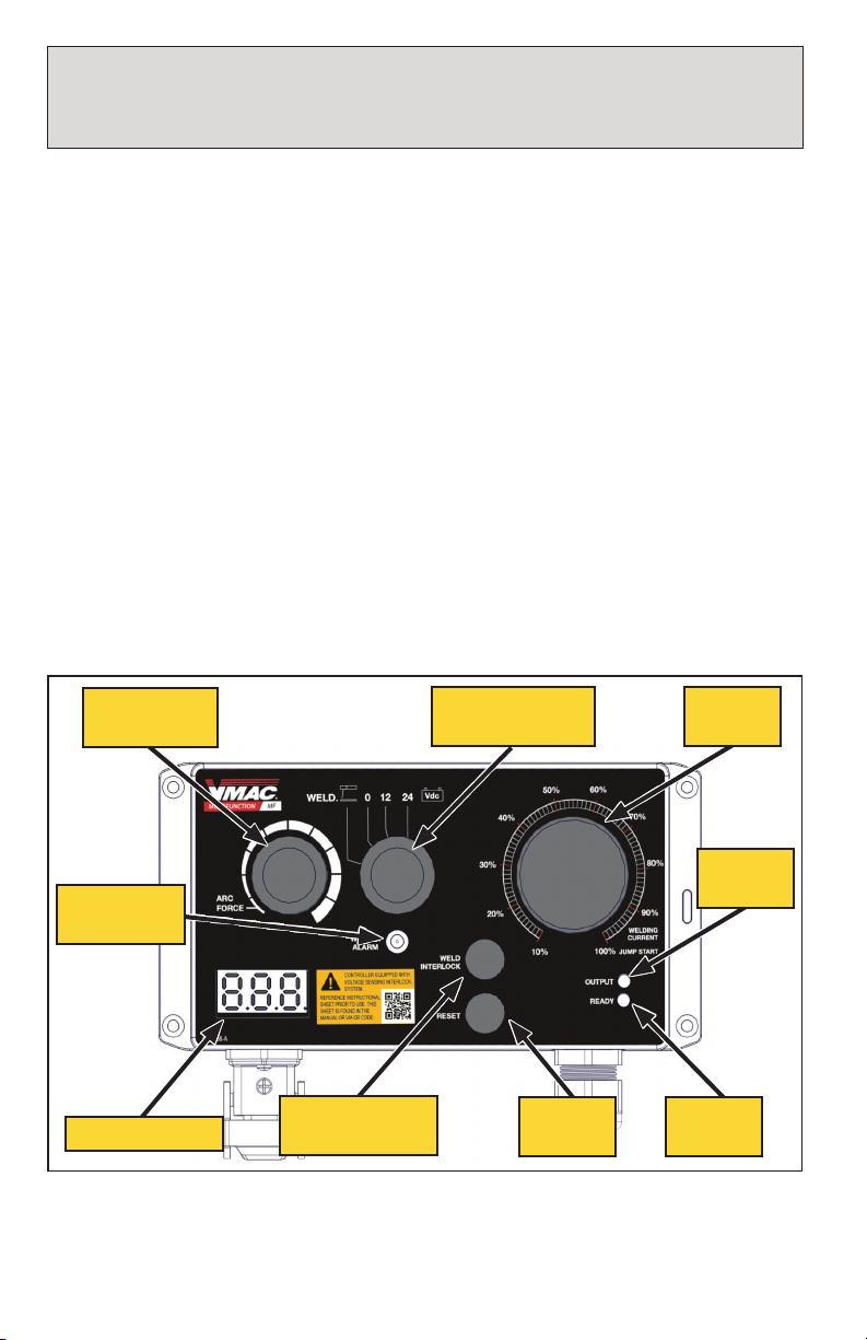
Figure 1 — Remote generator control box with Voltage Sense Interlock
Current
knob
Error
LED
On/Off
LED
Reset
button
Weld interlock
button
Voltmeter
ARC FORCE
knob
Weld/Charge
selection knob
Weld alarm
light
Installation
The Welder Control Box includes an 8 ft harness with (×4) plugs.
☐ Mount the Welder Control Box in a convenient location that is protected from
the weather.
☐ Locate harness bundle with the connectors near the main air discharge from
the MF.
☐ Plug one side of the “T” harness with the (×2) flat 5-pin connectors into the
matching connector at the MF unit and the other side into the connector
running to the rocker switches on the Display Panel.
Note: If using the pigtail extension harness, the welder control box should be
installed on the side closest to the rocker switch panel.
☐ Connect the (×2) Welder Control Box connectors into the matching connectors
in the main harness bundle.
Operation
This generator has been equipped with a voltage monitoring circuit to ensure that
charging/welding voltages are operating correctly for the intended process.
The order of operations for connecting batteries or moving the system into weld
mode must be followed exactly or the system disables itself and the generator must
be reset.
VMAC - Vehicle Mounted Air Compressors
VMAC Technical Support: 888-241-2289
VMAC Knowledge Base: kb.vmacair.com
9
If the battery voltage is too low,*.
☐ *Disconnect the battery from all loads. This may allow the battery voltage
to rise high enough to be recognized by the system.
☐ *If the battery does not recover adequate voltage after being disconnected,
battery detection can be temporarily over-ridden by pressing and holding
both the “RESET” and “BATTERY INTERLOCK” button for 5 seconds.
☐ With the battery connected, rotate the “WELD” selection knob to the
appropriate charge mode*.
☐ *The voltage should rise as the system begins charging.
☐ Set the “WELDING CURRENT” knob to 100%.
Charging / Boosting Procedure
Working near lead/acid batteries is dangerous. Batteries contain
sulphuric acid and may generate hydrogen gas during regular
operation. Lead/acid batteries may explode if exposed to a spark.
Never attempt to jump start a frozen battery.
Never overcharge a battery.
Always follow safety precautions when jump starting or charging
a battery, including the use of appropriate Personal Protective
Equipment.
☐ Prior to charging or boosting, ensure the MF is not running, and the booster
cables are disconnected from the battery to be charged.
☐ Set the “WELD” selection knob to 0 V.
☐ Start the MF.
☐ Engage the generator via the toggle switch located at the display box.
☐ The voltmeter should read approximately 0 V.
If “ErX” is displayed*:
☐ *Ensure the booster cables are not shorted together, or connected to the
batteries to be charged, and the “WELD” selection knob is set to “0”.
☐ *Press and hold the “RESET” button for 2 seconds.
☐ Connect the positive clamp to the positive terminal on the battery.
☐ Connect the negative clamp to a good ground (ideally on the engine).
Observe the battery voltage using the Voltmeter*.
☐ *12 V systems should indicate battery voltage above 2.0 V.
☐ *24 V systems should indicate battery voltage above 14.0 V.
If the battery voltage is below the above values, the generator will
not recognize the target and will not unlock the appropriate charge
modes.
Once switched into charge mode, the system will re-enable battery
detection after 60 seconds.

VMAC - Vehicle Mounted Air Compressors
VMAC Technical Support: 888-241-2289
VMAC Knowledge Base: kb.vmacair.com
10
☐ Return the “WELD” selection knob to 0 V.
Weld Procedure
☐ Let the batteries charge for at least 5 minutes.
☐ Try starting the vehicle.
While the MF can provide up to 300 A of start assist, vehicle
starters can draw upwards of 1,200 A while starting.
If the vehicle fails to start, allow it to charge for longer before
attempting to start again.
☐ Prior to starting the Gas MF, set the “WELD” selection knob to 0 V.
☐ Start the Gas MF.
☐ Engage the generator via the toggle switch located at the display box.
☐ The voltmeter should read approximately 0 V.
☐ If “ErX” is displayed*:
☐ *Ensure the weld cables are not shorted together, or connected to the batteries
to be charged, and the “WELD” selection knob is set to “0”.
☐ *Press and hold the “RESET” button for 2 seconds.
☐ Press and hold the “WELD INTERLOCK” button while rotating the “WELD”
selection knob to “WELD”.
☐ If using the optional Current Control Pendant (P/N: A500018), plug it into the
Remote Generator Control Box.
☐ Adjust the “WELDING CURRENT” and “ARC FORCE” as required.
☐ Once welding is complete:*
☐ *If using the Current Control Pendant, disconnect it.
☐ *Set the “WELD” selection knob to 0 V (The “WELD INTERLOCK” button is
not required when returning the “WELD” selection knob to 0 V).
Plugging the optional Current Control Pendant (P/N: A500018) into
the Remote Generator Control Box prior to entering "WELD" mode
will cause an error.
VMAC - Vehicle Mounted Air Compressors
VMAC Technical Support: 888-241-2289
VMAC Knowledge Base: kb.vmacair.com
11
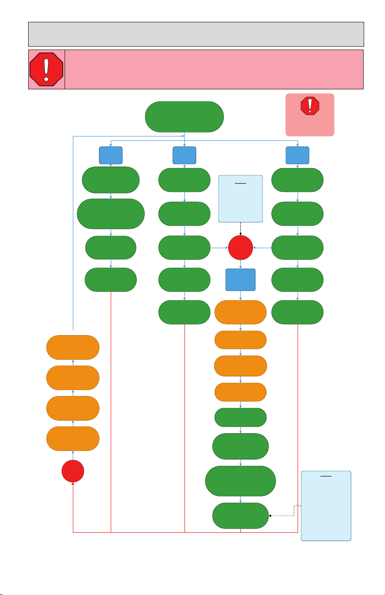
Getting Started Guide
•Ensure boost cables are
disconnected from all loads &
accessories are unplugged
•Start Multifunction
•Genset Switch ON
12V
BOOST
24V
BOOST
WELD
ERROR?
Ensure Weld/Charge
Selection Knob set to
“0V” position
Press & Hold
“RESET” button for 2
seconds
Disconnect boost
cables from all loads
Ensure Weld/Charge
Selection Knob set to
“0V” position
Ensure Weld/Charge
Selection Knob set to
“0V” position
While pressing
“WELD INTERLOCK” button,
move weld/charge selection
knob to “WELD” position
Verify output
voltage on display
Connect boost cables
to 12V battery
Move Weld/Charge
Selection Knob to
“12V” position
Connect boost cables
to 24V battery
Move Weld/Charge
Selection Knob to
“24V” position
Ready to weld Verify output
voltage on display
ERROR 1?
Move Weld/Charge
Selection Knob to
“0V” position
Press & Hold
“RESET” button for 2
seconds
Ready to boost 12V
Press & hold both
“WELD INTERLOCK” &
“RESET” buttons for 5
seconds
Connect boost cables
to 12V or 24V battery
Move Weld/Charge
Selection Knob to
“0V” position
Disconnect boost
cables from all loads
Move Weld/Charge
Selection Knob to
“12V” or “24V” position,
depending on connected
battery
Verify output
voltage on display
Ready to boost 24V
System will boost for
60s and re-measure
battery voltage
TEMPORARY
BATTERY
DETECT
OVERRIDE
INFO
“ERROR 1" occurs
when battery
voltage is less than
2V for 12V battery
or less than 14V for
24V battery
INFO
If battery voltage is
still too low after 60s
of boost, the system
will detect an error
and the override
process must be
repeated until battery
voltage is greater than
2V for 12V battery or
greater than 14V for
24V battery
REV005
Refer to warnings on
pg.8 of installation
manual before use
Refer to warnings on
pg.8 of installation
manual before use
Refer to warnings on
pg.8 of installation
manual before use
Refer to warnings on
pg.8 of installation
manual before use
Disconnect all
accessories from
remote weld box
Disconnect all
accessories from
remote weld box
Read the warnings listed on page 9 prior to proceeding.

VMAC - Vehicle Mounted Air Compressors
VMAC Technical Support: 888-241-2289
VMAC Knowledge Base: kb.vmacair.com
12
Weld Control Box Error Messages
If the voltmeter detects a voltage or state that is not permitted, an error will be
displayed on the screen.
If an error is displayed:
☐ Disconnect the target battery and ensure the booster, or weld cables are not
shorted together.
☐ Return the “WELD” selection knob to 0 V.
☐ Press and hold the “RESET” button for 2 seconds.
☐ If the error persists, contact VMAC for support.
Error Description Corrective Action
Er 0 Voltage detected above bounds
for selected mode.
Gas MF output voltage is greater than 20 V (12 V
boost mode) or 38 V (24 V boost mode).
• Reset system and re-attempt boost procedure.
• Contact Technical Support.
• Remote Current Control Pendant plugged in prior
to setting "WELD" mode (see page 10).
Er 1 Voltage detected under bounds
for selected mode.
Target battery is less than 2 V (12 V boost mode) or
14 V (24 V boost mode).
• Check connection between Gas MF boost cables
and target battery.
• Charge target battery in override mode to
allow battery voltage to rise high enough to be
recognized by system.
• Target battery float voltage is too low to be
charged.
Er 2 Reverse polarity detected.
Reverse polarity of connection from Gas MF boost
cables to target battery.
• Check connection between Gas MF boost cables
and target battery. Verify correct polarity
(+ to + and - to -).
Er 3 Incorrect mode detected.
Incorrect charge mode selected for detected target
battery voltage.
• WELD INTERLOCK button not pressed while
entering WELD mode.
• System not started in 0 V mode, Refer to
page 44.
• Select correct charge mode according to target
battery voltage.
Er 4 Multifunction battery low.
Gas MF battery voltage less than 9.0 V.
• Inspect cables/connections to Gas MF battery.
• Service/replace Gas MF alternator.
Er 5 Multifunction battery high. Gas MF battery voltage greater than 16.0 V.
• Service/replace Gas MF alternator.
Er 6 MCU Reset.
• Inspect wiring harness for damage, short/open
circuit.
• Contact VMAC Technical Support.


888-241-2289 tech@vmacair.com
877-740-3202 warranty@vmacair.com
www.vmacair.com kb.vmacair.com
1333 Kipp Road, Nanaimo, B.C., V9X 1R3 Canada
Manufactured by
®
Table of contents
Other Vmac Automobile Accessories manuals

Vmac
Vmac V910020 Service manual

Vmac
Vmac A500251 User manual

Vmac
Vmac A700308 User manual

Vmac
Vmac VR 7000 9004 User manual

Vmac
Vmac A500237 User manual

Vmac
Vmac A700137 User manual

Vmac
Vmac VR7000 9037 User manual

Vmac
Vmac VR 7000 9018 User manual

Vmac
Vmac A700269 User manual

Vmac
Vmac VR7000 9039 User manual

Popular Automobile Accessories manuals by other brands


ULTIMATE SPEED
ULTIMATE SPEED 279746 Assembly and Safety Advice

SSV Works
SSV Works DF-F65 manual

ULTIMATE SPEED
ULTIMATE SPEED CARBON Assembly and Safety Advice

Witter
Witter F174 Fitting instructions

WeatherTech
WeatherTech No-Drill installation instructions

TAUBENREUTHER
TAUBENREUTHER 1-336050 Installation instruction