2
VMAR and POLYCOTE are Trademarks of VMAR Manufacturing and
authorized VMAR Agents worldwide. Copyright Richmond RC Supply Ltd
TM
CARE & MAINTENANCE OF POLYCOTE ECS.
POLYCOTE ECS is a proprietary Enhanced Covering System engineered in Canada &
available only from VMAR. With POLYCOTE ECS the graphics are inside the covering... not
stuck on top. No Decals! No Layers! No Strips! No Stripes! POLYCOTE ECS utilizes ULTRA
TOUGH polyester and our SURE SEAL system to ensure that the seams stay down! Best of all POLYCOTE is totally fuel
proof! Quite simply... POLYCOTE ECS leads the pack in ARF covering systems!
By putting the graphics inside the POLYESTER covering... we've reduced the need for maintenance to a minimum. No
seams to pick up, very few edges, extraordinary fuel proofing etc. With POLYCOTE ECS you will spend more time flying
and less time reworking the covering! Polyester offers the best in covering performance and as with any POLYESTER
covering here are a few tips to make it even easier to keep POLYCOTE ECS looking it's best!
CARE: Avoid puncturing. Avoid leaving your model in a closed car exposed to direct heating from the sun for lengthy
periods. Temperatures under such conditions can exceed 50C (122F) and sagging may occur.
TIGHTENING: To tighten POLYCOTE ECS we recommend using a medium-high temperature heat iron on the seams, edges, around
perimeters and over solid surfaces. Use a heat iron "sock" on the iron and push down firmly on the covering over solid areas to bond
the covering to the underlying substrate. Work with the iron set at 250-300F. You may also work with a heat gun over solid surfaces
provided that all edges and seams are set with a heat iron first. If using a heat gun over solid surfaces, make sure the edges are firmly set
with a heat iron first then use the heat gun to heat about 1 square foot of area at a time, then rub the warm covering down firmly with a soft
cotton cloth to bond the covering to the underlying substrate. DO NOT USE A HEAT GUN NEAR EDGES & SEAMS. Higher tempera-
tures may assist with complex curved surfaces. Use a medium-high temperature heat gun on POLYCOTE ECS applied over open
bays. Always practise on the bottom of a less noticable section first. Be patient and work systematically... you will likely only have to tighten
POLYCOTE once or twice to accomodate any shrinkage of the airframe in dry hot conditions.
RESEALING SEAMS: POLYCOTE ECS seams are sealed with our SURE SEAL system and will not normally lift. If you
find a loose edge, clean any oil residue from the area and the edge and reseal with thin CA.
PATCHING: If you puncture POLYCOTE ECS, clean any oil residue from the area of the puncture. We clean using Fantastic and
then a paper towel moistened Pacer De-Bonder or alcohol or water to remove any remaining residue from the surface. The patch
should be 1/2" bigger than the hole on all sides. We recommend using POLYCOTE patch sheets if provided with your model or
polyester covering such as POLYCOTE, ULTRACOTE or ORACOVER and the use of a heat iron and soft cloth. Monokote,
SolarFilm or V-COTE covering material will also work. Cut the patch with rounded corners. Seal the patch in place with a heat iron set
at 250F first and then tighten the patch and the original covering around the patch as outlined in the tightening section above. To repair
larger more extensive damage areas, you may wish to obtain the appropriate POLYCOTE ECS covering set for this model.
CLEANING AFTER FLYING: To clean POLYCOTE ECS after flying we recommend Fantastic household cleaner and
disposable paper towels. You can use just about any cleaner and we are not aware of any cleaner that will damage
POLYCOTE but it is a good idea to always test a small out of the way spot first. Wipe along seams, not across. To really
show off your POLYCOTE ECS covering, after cleaning wtih Fantastic... use a bit of Armorall and buff dry & shiny.
CLEANING INITIALLY: POLYCOTE ECS has very few seams and we use our SURE SEAL system to really lock the
seams down. Upon initial inspection if you see a thin streaky film on any of the POLYCOTE ECS when looked at under
bright light this is a residue from the SURE SEAL process. It is easily removed using Minerial Spirits (Paint Thinner,
Varsol). If you've ever painted with oil base paints you probably have Mineral Spirits on hand already, if not, it is readily
available at a paint or hardware store. It is recommended that you work with Mineral Spirits outdoors and follow the
directions on the container. Use a paper towel and wipe a slightly wet film of Mineral Spirits over 1/4 of a wing or half a
fuselage at a time. Rub gently while still wet. Change towels frequently. Use a clean towel to buff dry. If you want to
accentuate the deep "clear coat" gloss of POLYCOTE ECS even more, use a bit of Armorall and buff shiny with a clean
paper towel. Discard all soiled paper towels into a metal garbage can stored outdoors.
TM
Check for updates and more
information about
POLYCOTE ECS at
www.richmondrc.com/polycote.htm
CUTTING: POLYCOTE ECS is made from ULTRA TOUGH POLYESTER.
Where possible, use scissors to cut POLYCOTE. Scissors work well.
Otherwise use a new sharp #11 Blade. The blade must be SHARP.
S240X_Important_Info_20041022.pmd
REMOVING & USING TAPE: Tape may been used to hold control surfaces or other parts in place during shipping. When
removing tape from POLYCOTE ECS, peal the tape back on itself so that the pulling is parallel to the surface of the
covering. If the tape is near or across a seam or an edge, peal towards the edge or seam. Do NOT pull the tape up at
right angles to the covering or away from a seam or edge. If you use tape during the assembly process use a low tack
masking tape and remove it using the procedure noted above.
3
For more information that may be relevant to this model
please visit us at www.richmondrc.com/support.htm
Copyright Richmond RC Supply Ltd
VMAR is a Trademark of VMAR Manufacturing Inc. and authorized VMAR Agents worldwide
TM PLEASE READ EVERYTHING BEFORE ASSEMBLY!
STINGER
40-52 ARF TRAINER
S240X_Important_Info_20041022.pmd
3. OUR CONTROL HORNS are unique. They do not
look like most of the control horns you have seen before
and you may think they are missing. They are in the
control horn parts bag &/or wing parts bag inside the
master bag of hardware and consist of a metal bolt,
metal nut, beveled white plastic washer, a white plastic
T-nut and the white plastic control horn itself that
connects to a clevis or rod.
Control Horn Set Before Installation. Note 5 parts
make up the set.
Control Horn Set
Partially Installed
Control Horn Set Fully
Installed.
Note that the metal nut has
been tightened down snugly
against the top of the T-Nut as a
safety lock. Then the plastic
control horn is threaded on to
the metal bolt as shown.
Note that the bevelled washer
has the bevel side facing the
control surface and the flat
side against the head of the
metal bolt.
PLASTIC
T- NUT
BEVELLED
WASHER
METAL
BOLT
PLASTIC CONTROL
HORN METAL
BOLT
PLASTIC
T-NUT
FRONT
METAL
NUT
(Note: In Light Duty applications the Metal Nut
may not be included)
HINTS & TIPS
1. During construction, whenever you use epoxy, it MUST
BE 30 Minute Epoxy. Do not use faster cure time Epoxy...
Use good quality 30 Minute Epoxy only.
2. When first opening the box and reviewing the contents
here is a "what is where" list that you may find helpful...
- the
- the horizontal stab is packed between the wing halves
- the vertical stabilizer is near and beneath the fuselage
- the hardware bag is in a separate area near
- the
- the servo tray and control rods are in the fuselage
... CONTINUED PAGE 4
6. On Page 3 Stage 3 in pictures 3A, 3B & 3C you can see the
wing bolt holes cleared of covering. Before clearing the holes. wick
a bit of thin VCA into the covering area from inside the hole,
externally press the covering around the hole, let the CA dry, then
cut with a sharp #11 blade.
7. On Page 4 Stage 4 Fitting Aileron Servos, some servos have
a rubber boot strain relief around the wire coming from the servo.
Notch the bottom of the servo rails shown in picture 4D to clear
the rubber boot or wire if required.
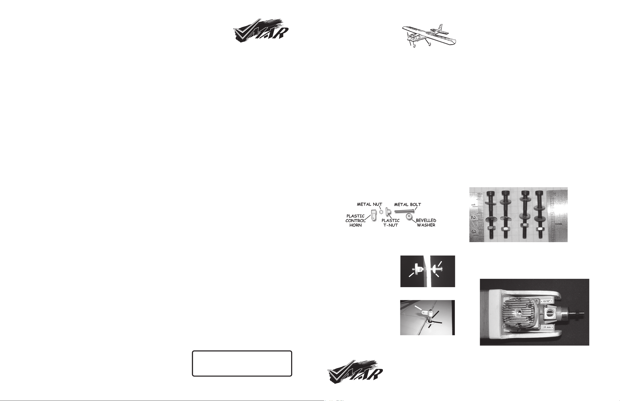
8. Page 10 Installing the Engine - Stage 17. The engine mount
has been pre-installed in the correct location. Depending on your
model and the date of manufacturer, your engine mount may
look slightly different than that depicted in 17B. If your engine
mount looks the same as shown in 17B and includes the metal
clamp plates then please follow the Stage 17 instructions to
install your engine.
If your engine mount does NOT have the metal clamp plates
illustrated in 17B then please use the following alternative
instructions to install your engine mount.
8.1 Locate the set of four engine mounting bolts, washers and nuts
in the hardware bag supplied with your model. See Figure A below.
FIGURE A
Engine
Mounting
Bolts,
Washers
& Nuts
8.2 Carefully remove your carburetor, muffler, spinner, prop etc
from your engine. Neatly apply masking tape to the top surface
of the engine mounts so that you can mark the mount with a pen
or pencil Place your engine on the engine mount so that the
front of the engine lugs are approximately 15/16 in. (24 mm)
from the front end of the engine mounts. See Figure B.
5. Before beginning Stage 1 Wing Assembly, remove any lockdown
material and/or foam pads from the wing. Be careful when removing
tape. Pull tape strips back on themselves... do not pull tape away
from the wing. Be very careful when removing tape that crosses a
seam or edge in the covering. Remove any Tape Residue with
alcohol or other not abrasive solvent. Test small area first.
4. During construction use Low Tack Masking Tape only. The
green painters masking tape works well.
FIGURE B


 quick start guide")


