Step 18.1 Consult your radio manual for instructions about
hooking up your receiver.
Step 18.2 Plan where you are going to put the receiver
with consideration for routing the antenna safely.
Step 18.3 Wrap the receiver securely in foam suitable for
RC equipment and wrap the foam insulated receiver in a
plastic bag or cling wrap.
Step 18.4 Install your receiver near the aft end of the fuse-
lage as shown in 18B.
INSTALLING THE RECEIVER BATTERY
STAGE
17
Step 17.1 Consult your radio manual for instructions about
hooking up your receiver battery, receiver and switch har-
ness.
Step 17.2 Wrap the battery pack securely in foam suitable
for RC equipment and wrap the foam insulated pack in a
plastic bag or cling wrap. Position the battery pack as
shown in 18B.
Step 17.3 Thread the battery pack connector forward in
preparation for connecting to your switch harness.
Step 17.4 Connect the battery pack connector to your
switch harness according to your radio manual.
With the throttle control arm connected to the engine throttle arm ensure that the throttle servo moves the throttle barrel
from nearly closed to fully open.
Adjust the deflection of the control surfaces to match the
specifications on page 11. You can reduce the amount of
throw by doing either or both of the following:
- From the servo end, move the clevis or EZ connector to a
hole in the servo arm that is closer to the servo output shaft.
- From the control horn end, move the horn out further on
the threaded bolts. Always confirm that the horn is still
thoroughly engaged with the threaded bolt after you have
adjusted it.
8
CONNECTING THE THROTTLE CONTROL
STAGE
14
14B- The throttle servo controls the
engine throttle using the throttle con-
trol rod
14C- Completed engine with throttle
control connected and muffler
installed
14A- Throttle control rod connected to
the engine throttle arm
ADJUST CONTROL SURFACE THROW LIMITS
9
STAGE
15
FINAL RC SET-UP
STAGE 16
Step 16.1 Before starting the final set-up of the model,
switch on the radio and ensure that all trims are in their
neutral positions. Check that the aileron, elevator and rud-
der are centered. If any adjustments are needed, do these
by uncoupling the relevant clevis and turning it clockwise to
shorten the linkage or counter - clockwise to lengthen it.
Only when each control surface has been centered
mechanically in this way should you begin adjusting the
surface movement (or throw).
Step 16.2 Now confirm that the control surfaces are mov-
ing in the correct direction. Use the servo reversing switch-
es on your transmitter to reverse the direction of a servo if
necessary.
INSTALLING THE RECEIVER
STAGE
18
TAIL
Throttle
control rod
NOSE
TAIL NOSE
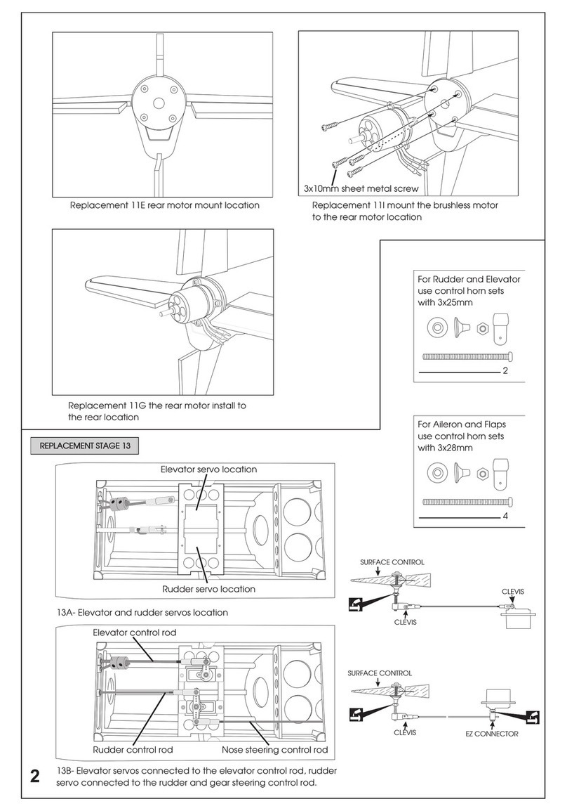
Step 13.1 Align the rudder with the vertical stabilizer and fuselage using a Bulldog paper clamp.
Step 13.2 With the rudder aligned straight with the fuselage. Turn over the fuselage and install the rudder control horn with
the EZ-connector installed. See 13C
Step 13.3 With the rudder aligned straight with the fuselage connect the rudder servo to the receiver and turn on your trans-
mitter. Ensure the rudder servo is centered at neutral.
Step 13.4 Connect the rudder control rod between the rudder servo arm and the rudder control horn EZ-connector. Tighten
the EZ-connector set screw firmly and ensure it is secure. Use medium thread locker (Blue). See 13D
Step 13.5 Connect the nose gear steering rod to the opposite side of the rudder servo arm. See 13D
13B- Align rudder with Bulldog paper clamp
13A- Rudder control horn assembly
13D- Rudder control rod installed between the rudder
servo and rudder control arm. Nose gear steering rod
connected to opposite side of servo arm
13C- Rudder control horn installed on the rudder control
rod
INSTALLING THE RUDDER
& NOSE WHEEL CONTROL SYSTEM
STAGE 13
TAIL NOSE
12B- Pre-installed elevator torque
rods & servo rails
12A- Elevator control rod assembly 12C- Control horns pre-installed on
the elevator torque rods
12D- Mount the servos on the pre-
installed servo rails 12E- For each servo, connect the con-
trol rod between the servo arm and
the control horn
12F- Elevator servos and control rods
installed
2-1/2 in. (65 mm)


