VMI Viber X2 User manual

Vibraon Measurement Instruments
VIBER X1™ Manual
Manual Viber X1_121002.indd 1 10/3/12 9:26 AM
NYA LOGGAN!
VIBER X2™
Manual
VIBER X2™
Manual
Ver. 2.5
Refers to VIBER X2™ rev: 1.7
Software 5.0


1
Vibraon Measurement Instruments
Our X series of hand-held instrument
VIBER X1 VIBER X2 VIBER X3
VIBER X5
Manual Viber X1_121002.indd 2 10/3/12 9:26 AM
VIBER X1™VIBER X2™VIBER X3™
VIBER X5™
Our x-series of hand-held instrument

Vibration measurements in progress

Index
1 Important information 4
2 Introduction 5
2.1 Scope of supply 6
2.2 Instrument keypad and LED’s 6
2.2.1 ON/OFF and Menu Key 7
2.2.2 Arrow keys 7
3 Vibration measurement screen 7, 8, 9
4 Warning messages 10, 11
5 Battery status bar 11
5.1 Changing Battery 11
6 How to interpret vibration levels 11, 12
6.1 ISO standard 10816-3 10 12, 13
7 Vibration analysis 14
7.1 Recommended vibration levels in 14, 15
mm/sandcommonndings
7.2 Recommended bearing 16, 17
condition levels
8 Technical data 18, 19
Vibraon Measurement Instruments
Important information
Safety precautions
Vibration measurement and balancing involves measurement on rotating machines.
Keep a safe distance to rotating parts and secure transducers and transducer cables
from rotating parts. Always follow internal, local and national security
regulations! When working with weights on the rotor always secure the start
switch with a locker and also use the emergency switch for double safety. This is
especially important when the machine is remote controlled.
VMI International AB takes no responsibility for any accidents on people and
machines.
VMI International AB and our authorized dealers will take no
responsibility for damages on machines and plants as the result
of the use of VIBER X1™ measurements.
Even though great efforts are made to make the information in
this manual free from errors and to make the information
complete for the user, there could be items we have missed,
because of the large amount of information. As a result of this,
we might change and correct these items in later issues without
further notice. Also changes in the VIBER X1™ equipment may
take place that affect the accuracy of the information.
Manual Viber X1_121002.indd 3 10/3/12 9:26 AM

4
1 Important information
Safety precautions
Vibration measurement and balancing involves collecting
measurement on rotating machines. Keep a safe distance
away from rotating parts. Secure transducers and transdu-
cer cables from rotating parts. Always follow company,
local and national security regulations! When working
with weights on the rotor, always follow “lock out tag out”
procedures. Secure the start switch with a lock and also use
the emergency switch for double safety. This is especially
important when the machine is remote controlled.
VMI takes no responsibility for any accidents on people
and machines.
VMI and our authorized distributors take no responsibility
for damages on machines or plants as the result of the use
of VIBER X2TM measurements.
Even though great efforts are made to make the information
in this manual free from errors and to make the information
complete for the user, there could be items we have missed,
because of the large amount of information. As a result of
this, we might change and correct these items in later issues
without further notice. Also changes in the VIBER X2TM
equipment may take place that affect the accuracy of this
information.
Vibraon Measurement Instruments
Our X series of hand-held instrument
VIBER X1 VIBER X2 VIBER X3
VIBER X5
Manual Viber X1_121002.indd 2 10/3/12 9:26 AM

5
2 Introduction
VIBER X2™ is designed for technicians, mechanics, and
machine operators that need a reliable, fast, and easy to
use tool for basic condition monitoring checks in rough
conditions. The VIBER X2™ instrument has the following
features:
- Accurate measurements in 4 selectable frequency ranges.
- Real-time measurement of the total vibration level and
the Bearing Condition (BC), shown simultaneously.
- Measurement units and display are user selectable from the
following list:
•g-value=(RMS,PeakorPeak-Peak)
•a=m/s(RMS,PeakorPeak-Peak)
•V=mm/sec(RMS,PeakorPeak-Peak)
•V=inch/sec(RMS,PeakorPeak-Peak)
•D=mils(RMS,PeakorPeak-Peak)
•D=μm(RMS,PeakorPeak-Peak)
- Bearing Condition measurements in the frequency range
(0.5 -16 kHz).
- Bar indicator shows measurement stability.
- Fastandeasyfaultanalysisdisplayingthevehighestpeaks
frequecy in RPM or Hz in main screen display.
- Large dynamic range of the vibration signal (up to 50g).
- Low power consumption.
- High performance accelerometer.
- Easy to understand and operate.
- Advanced technology with DSP processor.
- Several languages are available.
- Adjustable Auto-shut off for energy saving.
- Dust and waterproof, for rough use (IP 65).
Vibraon Measurement Instruments
Important information
Safety precautions
Vibration measurement and balancing involves measurement on rotating machines.
Keep a safe distance to rotating parts and secure transducers and transducer cables
from rotating parts. Always follow internal, local and national security
regulations! When working with weights on the rotor always secure the start
switch with a locker and also use the emergency switch for double safety. This is
especially important when the machine is remote controlled.
VMI International AB takes no responsibility for any accidents on people and
machines.
VMI International AB and our authorized dealers will take no
responsibility for damages on machines and plants as the result
of the use of VIBER X1™ measurements.
Even though great efforts are made to make the information in
this manual free from errors and to make the information
complete for the user, there could be items we have missed,
because of the large amount of information. As a result of this,
we might change and correct these items in later issues without
further notice. Also changes in the VIBER X1™ equipment may
take place that affect the accuracy of the information.
Manual Viber X1_121002.indd 3 10/3/12 9:26 AM

6
2.1 Scope of supply
A complete delivery is:
¥VIBER X2™, machine condition analyzer
¥Embedded Lithium batteries
¥One high performance accelerometer
¥1 m transducer cable
¥Carrying case
2.2 Instrument keypad and LED’s
The VIBER X2™keypad has:
¥1 ON/OFF key
¥1 Menu key
¥4 arrow keys
¥3 LEDs*
*Green LED lights, when any key is pressed.
*Yellow LED lights, when the measurement is above
the set warning level.
*Red LED lights, when the measurement is above
the set danger level.
2.2.1 ON/OFF and Menu Key
Press the ON/OFF key to start or stop the instrument.
If the setting Auto-shut off is ENABLED, the instrument will automatically shut off after
60 seconds if no key is pressed. Five seconds before the auto-stop, a warning window
will appear on the screen. The user has 5 seconds to press any key, to avoid the shut
off.
The Menu key activates the settings menu from any measurement screen. To return to
measurement press the Menu key once more.
2.2.2 Arrow keys
In the Setting Menu, the LEFT and RIGHT arrows are used to change the value of the
selected item.
The UP and DOWN arrows are used in accordance with the active screen. For details,
see Chapter 3 (Screens description).
2.1 Scope of supply
A complete delivery is:
• VIBERX2™,machineconditionanalyzer
• EmbeddedLithiumBattery
• Accelerometer
• 1mtransducercable
• ACadapter
• Carryingcase
2.2 Instrument keypad and LED’s
The VIBER X2™ keypad has:
• 1ON/OFFkey
• 1Greenmenukey
• 4Arrowkeys
• 3LEDlights*
*Green LED lights, when any key is pressed.
*Yellow LED lights, when the measurement is above
the set warning level.
*Red LED lights, when the measurement is above
the set danger level.
2.1 Scope of supply
A complete delivery is:
¥VIBER X2™, machine condition analyzer
¥Embedded Lithium batteries
¥One high performance accelerometer
¥1 m transducer cable
¥Carrying case
2.2 Instrument keypad and LED’s
The VIBER X2™keypad has:
¥1 ON/OFF key
¥1 Menu key
¥4 arrow keys
¥3 LEDs*
*Green LED lights, when any key is pressed.
*Yellow LED lights, when the measurement is above
the set warning level.
*Red LED lights, when the measurement is above
the set danger level.
2.2.1 ON/OFF and Menu Key
Press the ON/OFF key to start or stop the instrument.
If the setting Auto-shut off is ENABLED, the instrument will automatically shut off after
60 seconds if no key is pressed. Five seconds before the auto-stop, a warning window
will appear on the screen. The user has 5 seconds to press any key, to avoid the shut
off.
The Menu key activates the settings menu from any measurement screen. To return to
measurement press the Menu key once more.
2.2.2 Arrow keys
In the Setting Menu, the LEFT and RIGHT arrows are used to change the value of the
selected item.
The UP and DOWN arrows are used in accordance with the active screen. For details,
see Chapter 3 (Screens description).
Vibraon Measurement Instruments
Our X series of hand-held instrument
VIBER X1 VIBER X2 VIBER X3
VIBER X5
Manual Viber X1_121002.indd 2 10/3/12 9:26 AM

7
2.2.1 ON/OFF and Menu Key
Press the ON/OFF key to start or stop the instrument.
If the setting Auto-shut off is ENABLED, the instrument
will automatically shut off after 60 seconds if no key is
pressed. Five seconds before the auto-stop, a warning
window will appear on the screen. The user has 5 seconds
to press any key, to avoid the shut off.
The Menu key activates the settings menu from any
measurement screen. To return to measurement press the
Menu key when the BACK function is selected.
2.2.2 Arrow keys
TheLEFTandRIGHTarrowsareusedtochangethevalue
of the selected item. The UP and DOWN arrows are used
to make choice available on the screen like enable, disable,
units, alarms frequence etc.
3 Vibration measurement screen
Initial screen, shown when starting the instrument.
Vibraon Measurement Instruments
Important information
Safety precautions
Vibration measurement and balancing involves measurement on rotating machines.
Keep a safe distance to rotating parts and secure transducers and transducer cables
from rotating parts. Always follow internal, local and national security
regulations! When working with weights on the rotor always secure the start
switch with a locker and also use the emergency switch for double safety. This is
especially important when the machine is remote controlled.
VMI International AB takes no responsibility for any accidents on people and
machines.
VMI International AB and our authorized dealers will take no
responsibility for damages on machines and plants as the result
of the use of VIBER X1™ measurements.
Even though great efforts are made to make the information in
this manual free from errors and to make the information
complete for the user, there could be items we have missed,
because of the large amount of information. As a result of this,
we might change and correct these items in later issues without
further notice. Also changes in the VIBER X1™ equipment may
take place that affect the accuracy of the information.
Manual Viber X1_121002.indd 3 10/3/12 9:26 AM
Indicates the battery status
Total Value
Unit
Frequence of the highest peak
Stability bar
Frequency range
Measurements status
Alarm levels
12,6
0,21
2180
6-1600 Hz
RPM
Bearing condition
8
Vibration measurement status can be one of following:
- Measuring (Vibration measuring is ongoing)
- Ranging (The instrument is calculating the best
measurement level range)
- Averaging (Averaging of the measured data)
- Stable (The measurement is stablized)
- Overow (The signal is too high – the measurement is
incorrect/not readable.)
In case of amplitude out of range, the value is shown as 3
stars(***).
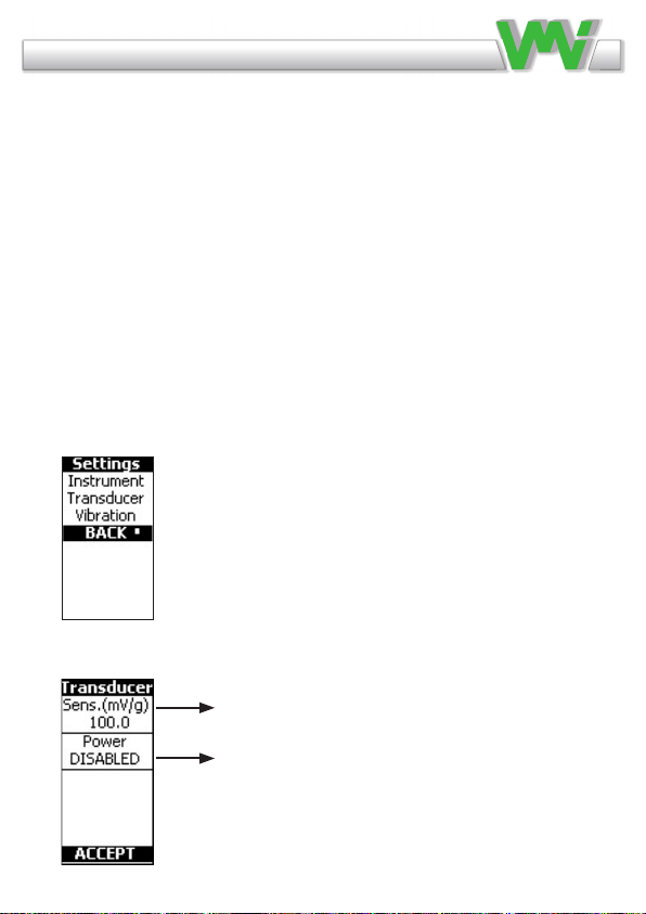
When the Menu key is pressed, the Settings menu is
displayed. Note that all accept/back are made with the green
menu key. The following settings are available:
Vibraon Measurement Instruments
Our X series of hand-held instrument
VIBER X1 VIBER X2 VIBER X3
VIBER X5
Manual Viber X1_121002.indd 2 10/3/12 9:26 AM
Select an item in the menu with the UP and
DOWN arrow keys. Open the selected item
with the green menu key.
Set actual sensors sensitivity
Disable power if sensor is external
powered
If transuducer setting is choosen, the following menu is displayed:

9
*Note:CanonlybeusedforvelocityunitRMS
Change the settings of the selected item with the LEFT and
RIGHTarrowkeys.
Vibraon Measurement Instruments
Our X series of hand-held instrument
VIBER X1 VIBER X2 VIBER X3
VIBER X5
Manual Viber X1_121002.indd 2 10/3/12 9:26 AM
Enable or disable
Enable or disable
20, 30, 40 sek / 1, 2 or 3 minutes
Choose language by pressing Arrow key
If vibration setting is choosen, the following menu is
displayed.
*Availablelanguagesare:English,Swedish,French,German,Romanian,
Spanish, Portuguese, Czech, and Finnish. For another language please con-
tact VMI’s disributors for availability.
If instrument setting is choosen, the following menu is displayed
g (RMS, Peak or P-P)
mm/s (RMS, Peak or P-P)
m/s2(RMS, Peak or P-P)
µm (RMS, Peak or P-P)
inch/sec (RMS, Peak or P-P)
mils(RMS, Peak or P-P)
Frequency range Hz Frequency range, where the
highest peak is displayed
2 - 400 Hz 2 - 400 Hz
6 - 1600 Hz 6 - 1600 Hz
11 - 3200 Hz 11 - 2000 Hz
10 - 1000 Hz 10 - 1000 Hz
Change of unit (see below)
Choose Hz or RPM
Enable*ordisablealarms
Alarm*settings
Alarm*settings
Change of frequency range (see below)

10
4 Warning messages
The following message may appear in normal operation:
This message may appear if the calibration
data is lost from the permanent FRAM
memory or if the calibration data are
corrupted. In such cases, the instrument must be recalibrated;
otherwise it will measure incorrectly. The message appears
only once, and then default calibration data is used.
When this message appears, the battery
voltage is too low to ensure a correct
running condition. The measurements may be
invalid! The instrument battery must be charged immediately,
using the external charger. To temporarily decrease the power
consumption, the backlight automatically will be switched
OFF. The instrument can still work, but only for a short while.
This message appears only if the Auto shut
off setting is enabled. The user may cancel
the shut off condition, pressing any key
except ON/OFF. If no key is pressed the instrument will shut
off in 5 seconds.
This message appears only if the Transducer
power setting is enabled and indicates that
the transducer is missing or is out of order.
When the Transducer power setting is disabled, the user has
the possibility to use another external source for the vibration
input (a signal generator or a buffered output from another
device).
Calibration
Battery
too low
Shut-off
in 5 sec
Missing
transducer
Vibraon Measurement Instruments
Our X series of hand-held instrument
VIBER X1 VIBER X2 VIBER X3
VIBER X5
Manual Viber X1_121002.indd 2 10/3/12 9:26 AM

11
When the instrument starts, the Transducer power setting
is always ENABLED. When this message appears, it will
remain on the screen, even if the transducer is plugged-in. To
continue the normal running mode in such a condition, switch
the screen temporarily to another menu. When you switch
back, the message disappears.
5 Battery status bar
In every measurement screen, at the upper side, a battery
status bar is shown.
The status bar indicates the battery voltage/energy content.
When the battery is charged, a connector symbol is
displayed. If voltage drops to less than 3.3 Volt, the
instrument will shut off.
5.1 Changing Battery
The unit has an embedded Lithium battery and we
recommend that a VMI reseller or service center makes
the replacement.
6 How to interpret vibration levels
User with no previous experience, we recommend to use the
ISO 10816-3 standard.
The standard normally calls for a velocity measurement in
mm/s RMS. To better understand what this measurement
means, think of it as how fast the machine is moving back and
forth. This measure gives a good understanding of the amount
of “break down energy”, causing mainly wear and fatigue in
This message appears only if the Auto-shut off setting is enabled.
The user may cancel the shut-off condition, pressing any key
except ON/OFF. If no key is pressed the instrument will shut off in 5
seconds.
This message appears only if the Transducer power setting is
enabled and
indicates that the transducer is missing or is out of order.
When the Transducer power setting is disabled, the user has the possibility to use
another external source for the vibration input (a signal generator or a buffered output
from another device).
When the instrument starts, the Transducer power setting is always ENABLED.
When this message appears, it will remain on the screen, even if the transducer is
plugged-in. To continue the normal running mode in such a condition, switch the screen
temporarily to another menu. When you switch back, the message disappears.
5 Battery status bar
In every measurement screen, at the upper side, a battery status bar is shown.
The status bar indicatesthe battery voltage/energy content.
When the battery is charged a connector symbol is
displayed. If voltage drops to less than 3.3 Volt, the instrument will shut-off.
3.1 Changing Battery
The unit has an embedded Lithium battery and we recommend that a VMI reseller or
service centre make the change.
4 How to interpret vibration levels
User with no previous experience, should use the ISO 10816-3 standard.
The standard normally calls for a velocity measurement in mm/s RMS. To better
understand what this measurement means, think of it as how fast the machine is
moving back and forth. This measure gives a good understanding of the amount of
“break down energy”, causing mainly wear and fatigue in the machine or the structure.
The instrument measures the total RMS vibration value in the frequency range. This
RMS value is the average sum of all the measured vibrations.
EXAMPLE:
If the simultaneous vibration caused by unbalance is (4mm/s), by misalignment (2
mm/s) and by the gear mesh (5 mm/s), then the total vibration measured on the
VIBER-X2 is 6.7 mm/s.
Shut-off
i n 5 sec
Mi ssi ng
tr ansduce
r
Vibraon Measurement Instruments
Important information
Safety precautions
Vibration measurement and balancing involves measurement on rotating machines.
Keep a safe distance to rotating parts and secure transducers and transducer cables
from rotating parts. Always follow internal, local and national security
regulations! When working with weights on the rotor always secure the start
switch with a locker and also use the emergency switch for double safety. This is
especially important when the machine is remote controlled.
VMI International AB takes no responsibility for any accidents on people and
machines.
VMI International AB and our authorized dealers will take no
responsibility for damages on machines and plants as the result
of the use of VIBER X1™ measurements.
Even though great efforts are made to make the information in
this manual free from errors and to make the information
complete for the user, there could be items we have missed,
because of the large amount of information. As a result of this,
we might change and correct these items in later issues without
further notice. Also changes in the VIBER X1™ equipment may
take place that affect the accuracy of the information.
Manual Viber X1_121002.indd 3 10/3/12 9:26 AM

12
the machine or the structure.
The instrument measures the total RMS vibration value in the
frequency range. This RMS value is the average sum of all
the measured vibrations. In the actual frequence range.
CALCULATION:
If the simultaneous vibration caused by unbalance is (4mm/s),
by misalignment (2 mm/s) and by the gear mesh (5 mm/s),
then the total vibration measured on the VIBER X2 is 6.7
mm/s.
6.1 ISO standard 10816-3
TheISOstandardclassiesthemachinesdifferentlyifthe
machinesareexibleorrigid.Thisreectsthelocationofthe
machine’s stiff-body resonance related to the basic
running speed of the machine.
For example, a machine supported by rubber or springs has a
resonance at low running speeds. The machine starts vibrate
at low RPM. When the speed is
increased above the resonance
frequency, the vibration is redu-
ced. This machine is considered
exible.
Resonance is easily found when
aexiblemachineisrunningup
or down in speed. The reso-
nances are located at the RPM
where the vibration has a local
maximum level. Modern machi-
nes that have high RPM’s and
Total vibration (RMS) =
4.1 ISO standard 10816-3
The ISO standard classifies the machines differently if the machines are flexible or
rigid. This reflects the location of the machine's stiff-body resonance related to the
basic running speed of the machine.
For example, a machine supported by rubber or springs have a resonance at low
running speeds. The machine starts vibrate at a low rpm. When the speed is increased
above these resonance frequencies, the vibration is reduced. This machine is
considered flexible.
Resonance is easily found when a
flexible machine is running up or
down in speed. The resonances are
located at the rpm where the
vibration has a local maximum
level.
Modern machines that have high
rpmʼs and flexible bearing supports
and foundations, can be treated as
flexible, even when they arenʼt
mounted on rubber or springs.
Group 1:
Large machines with rated power above
300kW.
Electrical machines with shaft height H
> 315mm.
Operating speed ranges from 120 to
15000 rpm.
Group 2:
Medium-sized machines with a rated power above 15kW up to and including 300kW.
Electrical machines with shaft height between
160 < H < 315 mm.
Operating speed normally above 600 rpm.
Group 3:
Pumps with multi vane impeller and with separate driver with rated power above 15kW.
Group 4:
Pumps with multi vane impeller and with integrated driver with rated power above 15kW.
The ISO 10816-3 standard allows for slightly higher limits when a foundation is
considered more flexible than rigid.
A conclusion from this is a resonance condition should not be allowed or at least must
be avoided at operating speeds. In practice, this also includes the double speed as well
as any other natural excitation frequency such as blade passage.
Vibraon Measurement Instruments
Our X series of hand-held instrument
VIBER X1 VIBER X2 VIBER X3
VIBER X5
Manual Viber X1_121002.indd 2 10/3/12 9:26 AM
Total vibration (RMS) = √4*4+2*2+5*5 = 6,7 mm/s

13
exiblebearing
supportsandfoundations,canbetreatedasexible,even
when they aren’t mounted on rubber or springs.
Group 1:
Large machines with rated power above 300kW.
Electrical machines with shaft height H > 315mm.
Operating speed ranges from 120 to 15000 RPM.
Group 2:
Medium-sized machines with a rated power above 15kW up
to and including 300kW.
Electrical machines with shaft height between
160 < H < 315 mm.
Operating speed normally above 600 RPM.
Group 3:
Pumps with multi vane impeller and with separate driver with
rated power above 15kW.
Group 4:
Pumps with multi vane impeller and with integrated driver
with rated power above 15kW.
The ISO 10816-3 standard allows for slightly higher limits
whenafoundationisconsideredmoreexiblethanrigid.
A conclusion from this is a resonance condition should not
be allowed or at least must be avoided at operating speeds.
In practice, this also includes the double speed as well as any
other natural excitation frequency such as blade passage.
Vibraon Measurement Instruments
Important information
Safety precautions
Vibration measurement and balancing involves measurement on rotating machines.
Keep a safe distance to rotating parts and secure transducers and transducer cables
from rotating parts. Always follow internal, local and national security
regulations! When working with weights on the rotor always secure the start
switch with a locker and also use the emergency switch for double safety. This is
especially important when the machine is remote controlled.
VMI International AB takes no responsibility for any accidents on people and
machines.
VMI International AB and our authorized dealers will take no
responsibility for damages on machines and plants as the result
of the use of VIBER X1™ measurements.
Even though great efforts are made to make the information in
this manual free from errors and to make the information
complete for the user, there could be items we have missed,
because of the large amount of information. As a result of this,
we might change and correct these items in later issues without
further notice. Also changes in the VIBER X1™ equipment may
take place that affect the accuracy of the information.
Manual Viber X1_121002.indd 3 10/3/12 9:26 AM

14
The next logical step is to use more advanced analyzers like
VIBER X3™ or VIBER X5™ to learn the frequency behind
the vibration and thus the exact mechanical fault.
The practice of this is beyond the scope of this manual.
7 Vibration analysis
7.1 Recommended vibration levels
The following is an extraction of part of the old standard ISO
2372class4,largemachinesonexiblefoundations,with
somecommonndingsadded.
Usethissimpliedlistasarstindication,whenapproaching
a newly commissioned machine or after some time in opera-
tion. Investigate the reason for any machine that vibrates
above 3 mm/s RMS.
• 0–3mm/s0–0,12in/s
Small vibrations - None or very small bearing wear. Rather
low noise level.
• 3–7mm/s0,12–0,28in/s
Noticeable vibration levels are often concentrated to some
specicpartaswellasdirectionofthemachine.Noticeable
bearing wear. Seal problems occur in pumps etc. Increased
noise level; try to investigate the reason. Plan an action during
next regular stop. Keep the machine under
observation and measure at shorter time intervals than
before to detect a deterioration trend if any. Compare
vibrations to other operating variables.
Vibraon Measurement Instruments
Our X series of hand-held instrument
VIBER X1 VIBER X2 VIBER X3
VIBER X5
Manual Viber X1_121002.indd 2 10/3/12 9:26 AM

15
• 7–11mm/s0,28–0,43in/s
Large vibrations. Bearings running hot. Bearing wear-out cau-
ses frequent replacements. Seals wear out, leakage of all kinds
evident. Cracks in welding and concrete foundations. Screws
and bolts are loosening. High noise level. Plan
action soonest. Do your best to discover the cause. You are
wearing down investments quickly.
• 11–mm/s0,43−in/s
Very large vibrations and high noise levels. This is
detrimental to the safe operation of the machine. Stop
operation if technically or economically possible. Few machi-
nes can withstand this level without internal or
external damage. Reduce any further running time to an abso-
lute minimum.
Vibraon Measurement Instruments
Important information
Safety precautions
Vibration measurement and balancing involves measurement on rotating machines.
Keep a safe distance to rotating parts and secure transducers and transducer cables
from rotating parts. Always follow internal, local and national security
regulations! When working with weights on the rotor always secure the start
switch with a locker and also use the emergency switch for double safety. This is
especially important when the machine is remote controlled.
VMI International AB takes no responsibility for any accidents on people and
machines.
VMI International AB and our authorized dealers will take no
responsibility for damages on machines and plants as the result
of the use of VIBER X1™ measurements.
Even though great efforts are made to make the information in
this manual free from errors and to make the information
complete for the user, there could be items we have missed,
because of the large amount of information. As a result of this,
we might change and correct these items in later issues without
further notice. Also changes in the VIBER X1™ equipment may
take place that affect the accuracy of the information.
Manual Viber X1_121002.indd 3 10/3/12 9:26 AM

16
Vibraon Measurement Instruments
Important information
Safety precautions
Vibration measurement and balancing involves measurement on rotating machines.
Keep a safe distance to rotating parts and secure transducers and transducer cables
from rotating parts. Always follow internal, local and national security
regulations! When working with weights on the rotor always secure the start
switch with a locker and also use the emergency switch for double safety. This is
especially important when the machine is remote controlled.
VMI International AB takes no responsibility for any accidents on people and
machines.
VMI International AB and our authorized dealers will take no
responsibility for damages on machines and plants as the result
of the use of VIBER X1™ measurements.
Even though great efforts are made to make the information in
this manual free from errors and to make the information
complete for the user, there could be items we have missed,
because of the large amount of information. As a result of this,
we might change and correct these items in later issues without
further notice. Also changes in the VIBER X1™ equipment may
take place that affect the accuracy of the information.
Manual Viber X1_121002.indd 3 10/3/12 9:26 AM
7.2 Recommended bearing condition levels
The bearing condition value is the total RMS value of the
acceleration of all high frequency vibrations within the
range from 500 Hz up to 16000 Hz with the unit “g”. Find
the machine speed. Follow this line up to the judgment lines
and read the value on the left axis.
The diagram on the next page is a guide to interpret the
bearing condition value. If vibrations of other causes (e.g.
owsurge,gearmesh)arewithinintheselectedfrequency
range, this can give a high bearing condition value without
any bearing faults. A high bearing condition value can also
be acquired if the bearing is poorly lubricated or is overloa-
ded (e.g. by misalignment, or large belt forces).

17
Vibraon Measurement Instruments
Important information
Safety precautions
Vibration measurement and balancing involves measurement on rotating machines.
Keep a safe distance to rotating parts and secure transducers and transducer cables
from rotating parts. Always follow internal, local and national security
regulations! When working with weights on the rotor always secure the start
switch with a locker and also use the emergency switch for double safety. This is
especially important when the machine is remote controlled.
VMI International AB takes no responsibility for any accidents on people and
machines.
VMI International AB and our authorized dealers will take no
responsibility for damages on machines and plants as the result
of the use of VIBER X1™ measurements.
Even though great efforts are made to make the information in
this manual free from errors and to make the information
complete for the user, there could be items we have missed,
because of the large amount of information. As a result of this,
we might change and correct these items in later issues without
further notice. Also changes in the VIBER X1™ equipment may
take place that affect the accuracy of the information.
Manual Viber X1_121002.indd 3 10/3/12 9:26 AM
17

18
Vibraon Measurement Instruments
Our X series of hand-held instrument
VIBER X1 VIBER X2 VIBER X3
VIBER X5
Manual Viber X1_121002.indd 2 10/3/12 9:26 AM
Technical data VIBER X2
Vibraon transducer Accelerometer Standard nom 100
mV/g
(Selectable sensivity in
the instrument)
0,1 - 99999 mV/g
Input amplitude range
Vibraon Max 50g RMS With other sensor up
to 500 g
Bearing condion Max 30 gBC
Dynamic range 80 dB (at 159 Hz with auto ranging)
Frequency range
Vibraon
2 - 400 Hz
10 - 1000 Hz
6 - 1600 Hz
11 - 3200 Hz
Note 1
Bearing condion 0.5 to 16 kHz
Vibraon units g-value, mm/s, mm/s2, in/s, µm, mils Note 2
Amplitude presenta-
on RMS, Peak, Peak-Peak Note 2
Analysis Five highest peaks can be displayed
Frequency range of
peak detecon
Frequency range
Note 3
2 - 400 Hz
6 - 1600 Hz
11 - 2000 Hz
10 - 1000 Hz
Accuracy
Vibraon ±3 % Note 4
Bearing condion ±5 % Note 4a
Frequency/RPM ±0.2 %
Baery Rechargable Lithium 2300 mA/h max 60°C Note 5
Operang me 1 week normal use
External charger 5,0 V regulated @ 2000 mA
LCD display B&W 64 x 120 pixels with background light Note 6
Enclosure protecon IP65
Operang temp. range 0 to 50°C Note 7
Weight 340 gram Note 8
Size (L x W x H) 145mm x 77mm x 47mm
Table of contents
Other VMI Measuring Instrument manuals


Popular Measuring Instrument manuals by other brands

ATI Technologies
ATI Technologies Q45S/87 O & M Manual

ATAGO
ATAGO MASTER Series instruction manual

Wagner Meters
Wagner Meters ORION 950 instruction manual

Veratron
Veratron VMH Series user manual

Alpha Moisture Systems
Alpha Moisture Systems SADPminiEx instruction manual

ALDON
ALDON 4022-26 instruction manual


