VMI X-Viber User manual

Instrument Manual
Ver. 1.01
12 April 2007
www.GlobalTestSupply.com
Find Quality Products Online at: sales@GlobalTestSupply.com

X-Viber manual
iii
Contents
CONTENTS ..................................................................................................................... III
HANDLING SECURITY ................................................................................................... V
SAFETY PRECAUTIONS ................................................................................................ V
WARRANTY DISCLAIMER ............................................................................................. V
DECLARATION OF CONFORMITY ................................................................................ VI
SWITCHING THE INSTRUMENT ON AND OFF ............................................................... 1
INTRODUCTION ............................................................................................................... 1
ROUTE MEASUREMENT ................................................................................................. 2
A MEASURING POINT IN THE ROUTE THAT HAS NOT YET BEEN MEASURED ................................ 2
A POINT IN THE ROUTE IN TIME OF MEASUREMENT .................................................................. 2
TOTAL VIBRATION ................................................................................................................ 2
A MEASURED POINT IN THE ROUTE ........................................................................................ 3
VIEW ALL ASSOCIATED MEASUREMENTS STORED IN THIS POINT .............................................. 3
TEMPERATURE MEASUREMENTS IN THE ROUTE ...................................................................... 4
SPEED IN THE ROUTE ........................................................................................................... 5
VIEW ALL POINTS OR MOVE BACK- AND FORWARDS IN THE ROUTE .......................................... 5
RE-MEASURE A SINGLE POINT IN THE ROUTE ......................................................................... 6
SPECTRA IN THE ROUTE (OPTIONAL) ..................................................................................... 6
DELETE ALL THE MEASUREMENTS IN THE ROUTE ................................................................... 7
TRANSFERRING A ROUTE TO THE X-TREND SOFTWARE .......................................................... 7
THE ROUTE SETTINGS MENU ................................................................................................ 8
OFF ROUTE MEASUREMENTS ....................................................................................... 9
MAIN MENU SETTINGS..................................................................................................... 10
MEASUREMENT SETTINGS MENU ......................................................................................... 10
TOTAL LEVEL .................................................................................................................... 11
THE TOTAL VALUE SETTINGS MENU ......................................................................... 12
www.GlobalTestSupply.com
Find Quality Products Online at: sales@GlobalTestSupply.com

X-Viber manual
iv
BEARING CONDITION ................................................................................................... 13
RECOMMENDED BEARING CONDITION LEVELS ...................................................................... 14
BEARING CONDITION SETTINGS MENU ................................................................................. 15
ENVELOPE ........................................................................................................................ 16
ENVELOPE SETTINGS MENU ............................................................................................... 17
SPEED .............................................................................................................................. 18
SPEED SETTINGS MENU ..................................................................................................... 19
TEMPERATURE .................................................................................................................. 20
TEMPERATURE SETTINGS MENU ......................................................................................... 22
HOW TO INTERPRET VIBRATION LEVELS.................................................................. 23
ISO STANDARD 10816-3 ................................................................................................... 23
LOOSENESS...................................................................................................................... 25
RECOMMENDED VIBRATION LEVELS IN MM/S AND COMMON FINDINGS .................................... 25
RESONANCE ..................................................................................................................... 26
ANALYSIS ...................................................................................................................... 27
ANALYSIS SETTINGS MENU ................................................................................................. 29
BALANCING ................................................................................................................... 30
BALANCING WITH X-VIBER ................................................................................................. 30
SCHEMATIC OF THE VIBRATION INPUT ..................................................................... 38
BATTERY ....................................................................................................................... 38
INSTRUMENT INFO MENU ............................................................................................ 39
BACKUP BATTERY ............................................................................................................. 40
RESETTING THE INSTRUMENT .................................................................................... 40
X-VIBER DEFAULT SETTINGS AFTER RESTART ....................................................... 41
www.GlobalTestSupply.com
Find Quality Products Online at: sales@GlobalTestSupply.com

X-Viber manual
v
Handling security
Safety precautions
Vibration measurement and balancing involves measurement
on rotating machines.
Always keep a safe distance to rotating parts and secure
transducers and transducer cables from rotating parts.
Balancing involves mounting of trial and balancing weights
on the rotor. Always secure the start switch with a locker and
also use the emergency switch for double safety before working with the rotor.
This is especially important when the machine is remote controlled.
VMI AB can not take responsibility for any accidents on people and machines.
VMI AB and our authorized dealers will take no responsibility for damages on machines
and plants as the result of the use of X-ViberTM measurements.
Even though great efforts are made to make the information in this manual free from
errors and to make the information complete for the user, there could be things we have
missed, because of the large amount of information. As a result of this, we might change
and correct these things in later issues without further information.
Also changes in the X-ViberTM equipment may take place that affect the accuracy of the
information.
Warranty disclaimer
VMI AB warrants the products to be free from defects in material and workmanship under
normal use and service within two years from the date of purchase and which from our
examination shall disclose to our reasonable satisfaction to be defective.
Warranty claimed products shall be returned prepaid to VMI AB for service. We reserve
the right to repair or to replace defective products.
Always try to explain the nature of any service problem, at best by fax, e-mail or letter.
Check first all natural problems, like empty batteries, broken cables, etc. When returning
the product, be sure to indicate that the purpose is to make repairs and indicate the
original invoice number and date of shipment to you, if possible.
www.GlobalTestSupply.com
Find Quality Products Online at: sales@GlobalTestSupply.com

X-Viber manual
vi
Declaration of conformity
Declaration of Conformity
Equipment: X-Viber
VMI AB declares that the X-ViberTM is manufactured in conformity with national and
international regulations.
The system complies with and is tested according to, following requirements:
EMC Directive: 89/336/EEC
Low Voltage Directive: 73/23/EEC
including amendments by Directive 93/68/EEC.
www.GlobalTestSupply.com
Find Quality Products Online at: sales@GlobalTestSupply.com

Switching the instrument ON and OFF
ON
Keep the ON/OFF button pressed until the instrument starts. Do this also, if the
instrument of some other reason is switch of or the display is empty.
OFF
Keep the ON/OFF button pressed in three seconds until the instrument is switched
off.
Introduction
Thank you for buying X-Viber: We have put a lot of efforts to make this instrument easy to
use and to give you valuable measuring results. The instrument is manly intended for
predictive maintenance work without the need for frequency analysis and “expert”
interpretation.
X-Viber has two main functions:
Route downloaded from the X-Trend PC software. With this function you can
measure 999 different measuring points and transferring the data back to the X-
Trend software for trend analysis and comparison with preset alarm values. The
address to the each measuring point is shown on the display.
In route you can measure and store:
The total vibration level within the selected frequency range
The total Bearing condition value within the selected frequency range
The total Envelope value within the selected frequency range
The speed of the machine because vibrations are highly dependent of the
speed
Bearing temperature
Analysis is a function to make temporary measurement on the machine but the
values are not stored.
In analysis you can measure:
The total vibration level within the selected frequency range
Analysis of the 5 highest vibrations with level and frequency. With this
function it is possible to make a simple analysis of the cause of the
vibration.
The total Bearing condition value within the selected frequency range
The total Envelope value within the selected frequency range
The speed of the machine because vibrations are highly dependent of the
speed
Bearing temperature
www.GlobalTestSupply.com
Find Quality Products Online at: sales@GlobalTestSupply.com
X-Viber manual
2
Route measurement
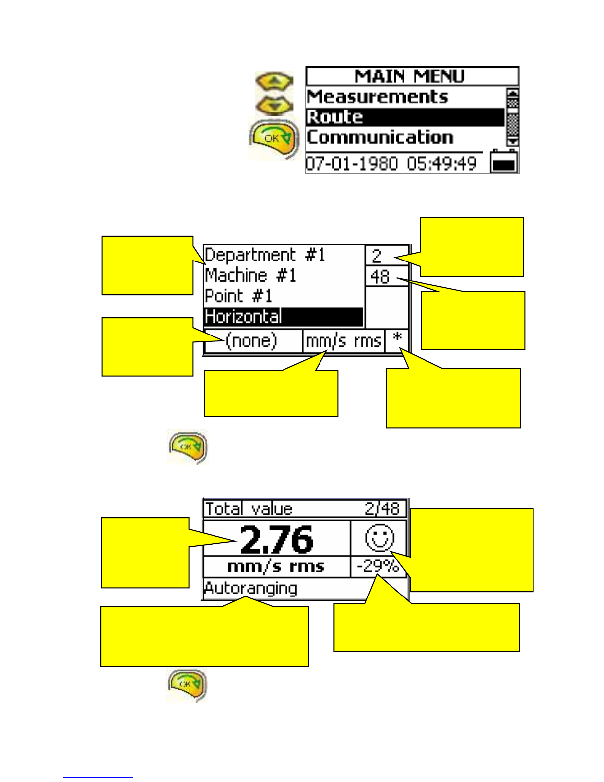
Move the black line over
Route with the Up or the
Down button and press the
OK button.
A measuring point in the route that has not yet been measured
Press the OK button to start the measurement.
A point in the route in time of measurement
Total vibration
Press the OK button to save the measurement and move to next measurement.
This window
shows the
address to the
measuring
point
This window
shows that this
point has not
been
measured.
This window shows the
selected unit and
average for this point.
This window
shows the point
number in the
route list.
This window
shows the total
number of points
in the route.
A star here shows that
also associated
measurement will
follow.
This window shows the changes in
percent compared with previous
measurement of the same point.
The measurement is unstable while the
text “Autoranging” appear.
Waite until this message disappears
before pressing the OK button.
This window shows
the current value
compared with the
alarm level.
A happy face = below
A sad face = above
Current
vibration value
with the unit
and average
below
www.GlobalTestSupply.com
Find Quality Products Online at: sales@GlobalTestSupply.com

X-Viber manual
3
A measured point in the route
Both the Bearing condition value and the Envelope value are measured at the same time
as the Vibration value if the instrument is set to measure these values in the X-Trend route
settings.
View all associated measurements stored in this point
The star indicates that there are associated measurements together with the Total
vibration value.
To view also the other values the Bearing condition and Envelope values you have to
press the AUX (or MODE ) button.
Then use Left or RIGHT arrow button to browse between the measurements.
Press the ESC button to exit to the normal route function.
The
stored
vibration
value
The stored value
compared with the alarm
level.
A happy face = below
A sad face = above
A star here
indicates that there
are also associated
measurements.
Note!
Because it is impossible to re-calculate a total velocity value to acceleration or
displacement X-Viber is always measuring and storing all these three values on
the same measuring point.
These three values are also transferred to the X-Trend software so the user can
change the unit at a later stage.
In METRIC mode the values are stored with the units “g”, mm/s and m.
In IMPERIAL mode the values are stored with the units “g”, in/s and mils.
www.GlobalTestSupply.com
Find Quality Products Online at: sales@GlobalTestSupply.com
X-Viber manual
4
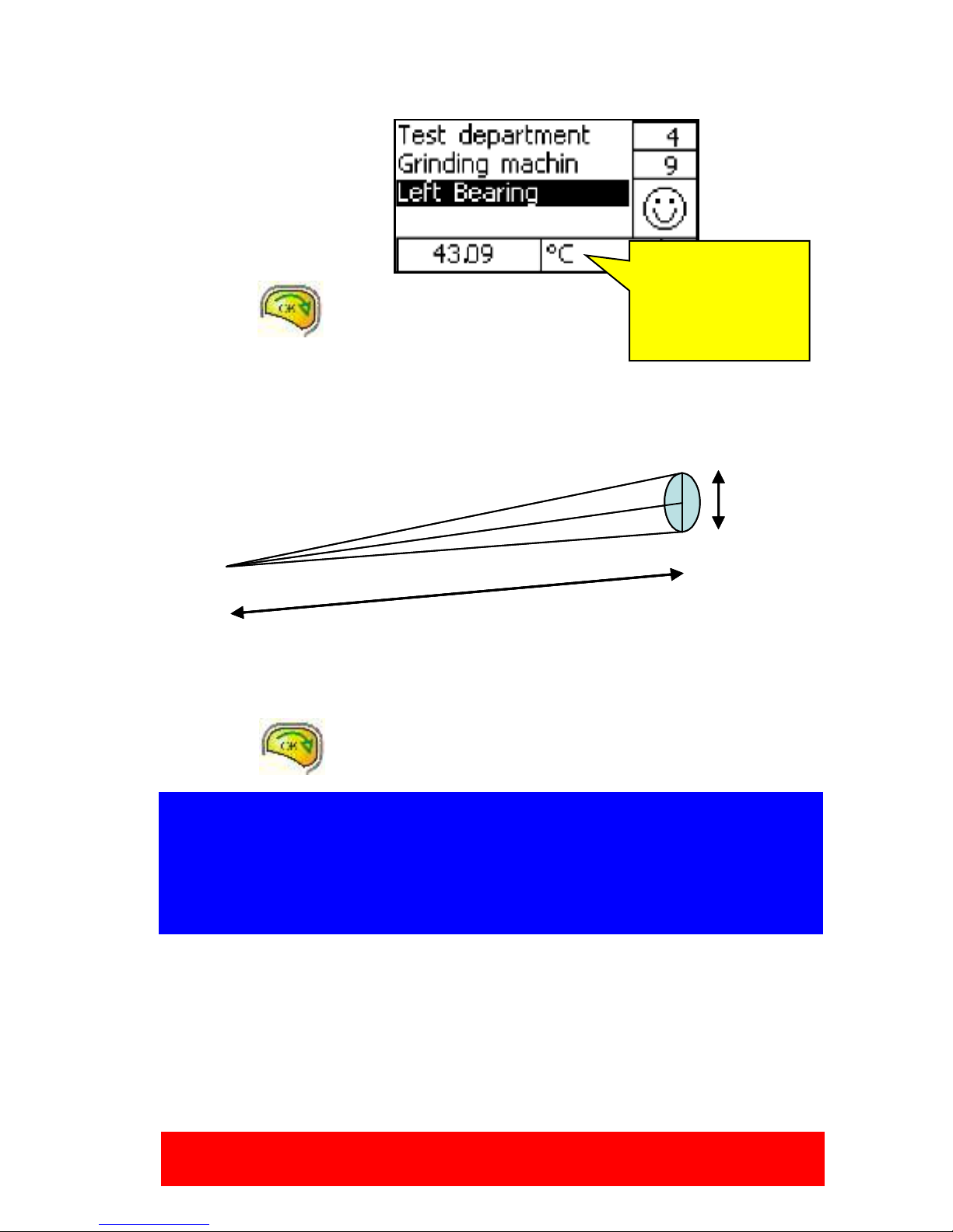
Temperature measurements in the route
A temperature measurement
is a separate point on the
bearing level because it is
enough to measure once on
each bearing.
Press the OK
button and the laser will start.
Direct the laser towards the
surface you want to measure.
Keep a distance of approximately 200-500mm between the instrument and the object.
Make the distance between the object and the instrument shorter the smaller the surface
you want to measure is.
Measuring surface related to distance 8:1
Move the laser point slowly until you find the highest temperature reading.
Press the OK button and the measurement is stored.
The unit for
temperature °C or
°F indicates that the
measurement is
temperature.
Warning!
This instrument is radiating laser light. Do not stare into the beam and do not
direct the laser beam to someones face.
Note!
This temperature sensor is measuring the heat radiating from the object.
A shiny or white surface will radiate less and will thus give a lower value.
To compensate for this the emissisivity factor can be changed but must be set
in the Temperature Settings in X-Trend and can not be adjusted in the Route.
8
1
8
1
www.GlobalTestSupply.com
Find Quality Products Online at: sales@GlobalTestSupply.com
X-Viber manual
5
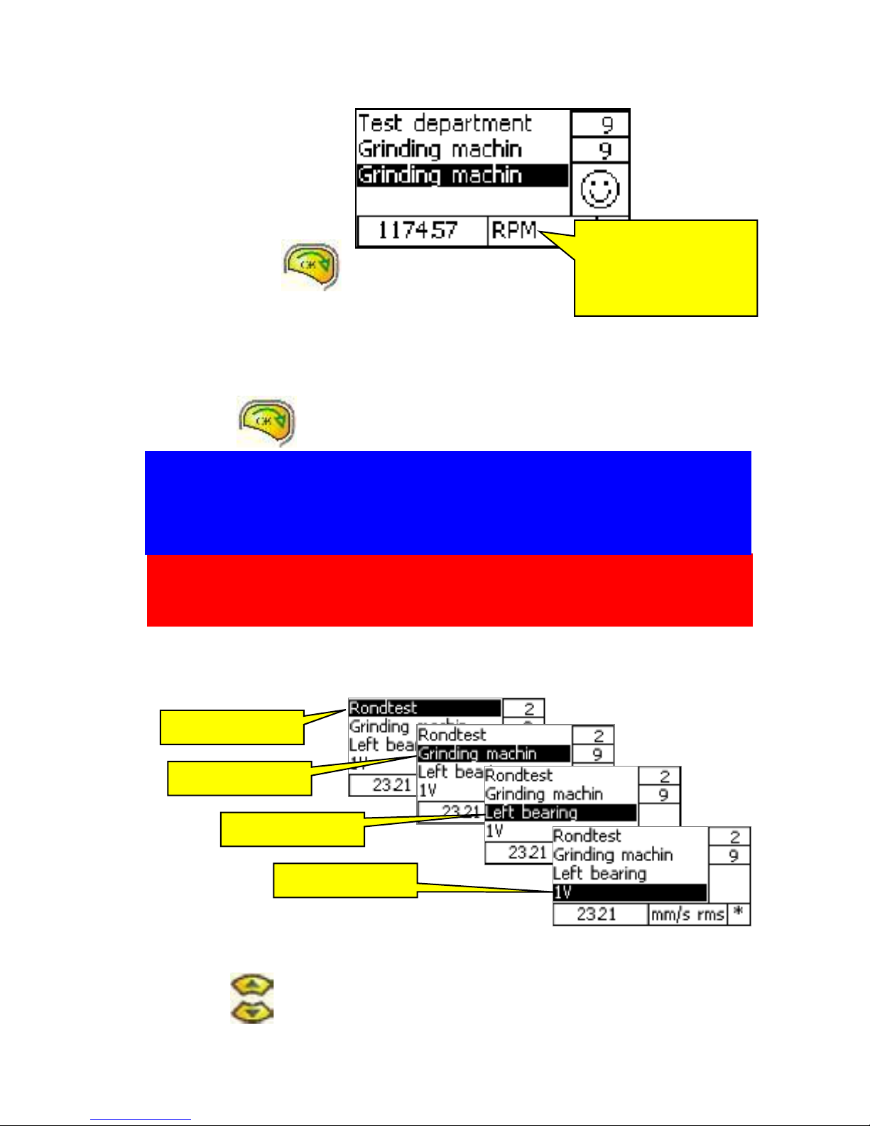
Speed in the route
A speed measurement is a
separate point on the
bearing level because it is
enough to measure once on
each shaft.
Press the OK
button and the
laser will start.
Direct the laser beam towards the reflex mark on the shaft.
Keep a distance of approximately 200-500mm between the instrument and the shaft.
Move the laser point slowly until you find the stabile speed reading.
Press the OK button and the measurement is stored.
View all points or move back- and forwards in the route
You can move in the route in all levels.
Select the level you want to move within by moving the black line with the
Up or Down buttons.
The higher level you choose the larger is the steps in the Route.
Department level
Machine level
Bearing level
Direction level
The unit for speed rpm
or Hz indicates that
the measurement is
speed.
Warning!
This instrument is radiating laser light. Do not stare into the beam and do not
direct the laser beam to someones face.
Note!
Direct the laser light in an angle towards the shaft reflex mark. This will give a
more stabile reading. Avoid directing the light in a perpendicular angle towards
the surface.
www.GlobalTestSupply.com
Find Quality Products Online at: sales@GlobalTestSupply.com

X-Viber manual
6
Press Left or Right buttons to move in the route.
With the Left button you will move backwards and with the Right button you will move
forwards in the route.
In the lowest level you will pass all directions in the
route.
This message will appear when you move backwards
and you reach the first point in the route.
Press the OK button and this message
disappears.
This message will appear when you move forwards
and you reach the last point in the route.
Press the OK button and this message
disappears.
Re-measure a single point in the route
Move to the point you want to measure again.
Press the OK button and this message will
appear.
Change to Yes with Left or Right buttons
and press the OK button and the instrument starts to measure.
Spectra in the route (optional)
To be able to see more than ten frequencies, the
function must be activated. Do the following:
From the main menu select Route
Go to the line Direction
Press the Menu
button
Go to the line Spectra:
With the Left or the Right
button select
YES and press OK.
Press the Escape button twice to come
back to the main menu
www.GlobalTestSupply.com
Find Quality Products Online at: sales@GlobalTestSupply.com

X-Viber manual
7
Delete all the measurements in the route
If you are measuring the same machines repeatedly and you seldom change to another
route you can keep the route in the instrument and only delete the measurements.
Press the Info button while you are
somewhere in the route and this window will appear.
Move the line with the Up or the Down
button to Clear measurement and change
to Yes with Left or Right
button and press the OK
button
Transferring a route to the X-Trend software
Start the transfer program in X-Trend.
Move the line with the Up
Or the Down button in the
MAIN MENU to Communication
and press the OK button.
Note!
When the measurements are deleted in this way, the comparison with previous
measurements will be false, because they will not be updated. The update can
only happen, when a new route is downloaded from the X-Trend software.
This message will appear if the
communication fails.
Check that the cables are connected
and that the USB driver for X-Viber is
installed.
www.GlobalTestSupply.com
Find Quality Products Online at: sales@GlobalTestSupply.com
X-Viber manual
8
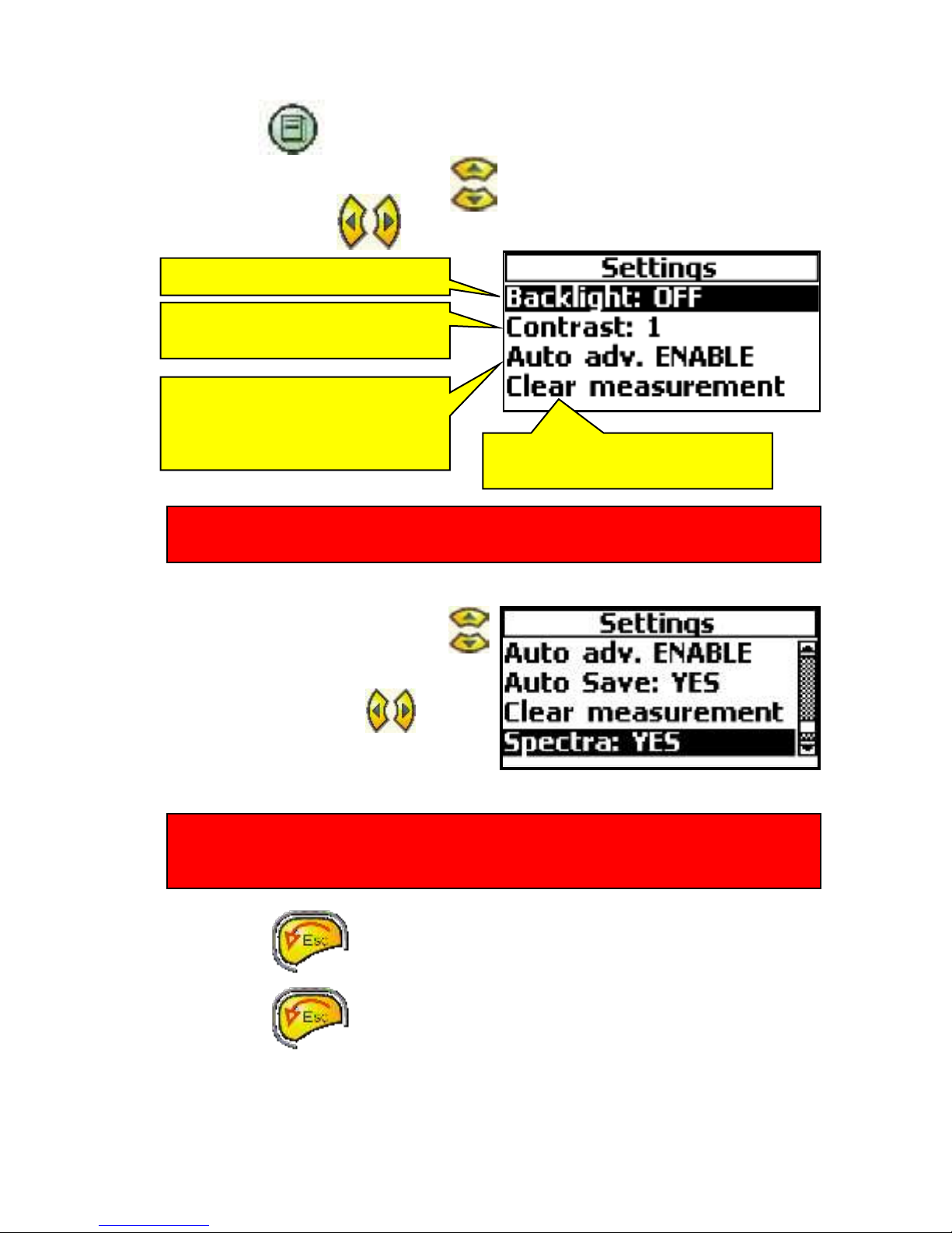
The Route settings menu
Press the Info button while you are somewhere in the route and this window will
appear.
Move the line with the Up or the Down button to the function you want to change.
Press the Left or Right button to change the settings.
Move the line with the Up or the Down
button to Spectra.
Press the Left or the Right button
to change to YES.
The X-Viber will not store the spectra in route if NO is selected.
Press the ESC button to exit to the normal route function.
Press the ESC button to leave the route function and go back to the Main
menu.
Turns the backlight ON or OFF
Change the contrast ratio.
A low number gives a higher ratio.
When enabled, the instrument will
automatically move to the next
point after the measurements are
finished.
Clear measurements are already
described on previous page.
Note!
If you have the option with spectra in route this function must be activated.
Note!
You can not see a spectrum in route in the X-Viber, but after transferring to the
SpectraPro software it is available.
www.GlobalTestSupply.com
Find Quality Products Online at: sales@GlobalTestSupply.com

X-Viber manual
9
This bar will appear when there are
more lines than shown in the
window.
Off Route Measurements
Move the line with the Up or the
Down button in the MAIN MENU to
Measurements and press the OK
button.
In the Measurements window you can select between the following functions:
Total value, this value is the RMS average of all vibrations within the selected
frequency range. You can select both unit and frequency range.
Bearing condition, this value is the RMS average in “g” of all high frequencies
within the selected frequency range.
Envelope, this value is the RMS average in “gE” within the frequency range 2-
1000Hz of the low pass filtered and rectified high frequencies between 500 to
7200Hz. You can select between different frequency ranges.
Speed, X-Viber is remotely measuring the shaft speed between 30 to 12000
rpm by sensing the infrared reflex from a target on the shaft. The target can be
any reflex tape.
Temperature, X-Viber is remotely measuring the object temperature within the
temperature range 0-120°C or -32 to 184°F by sensing the infrared radiation.
Analysis, This function is similar to the Total value but with an additional
analysis of the 5 dominating frequencies in the signal. This function is especially
useful to find the cause of the vibration and at balancing. You can select both
unit and frequency range.
Warning!
You can not store the measurements made in the Measurements mode.
This part is only for temporary measurements.
Take notes if you want to record some measurements.
www.GlobalTestSupply.com
Find Quality Products Online at: sales@GlobalTestSupply.com
X-Viber manual
10
MAIN MENU settings
Press the Info button and this window will appear.
Move the line with the Up or the Down buttons to the function you want to change.
Press the Left or the Right button to change the settings.
The settings in the MAIN MENU settings menu will automatically be used as soon as this
window is closed.
Press the ESC or OK button to exit to the MAIN MENU.
Measurement settings menu
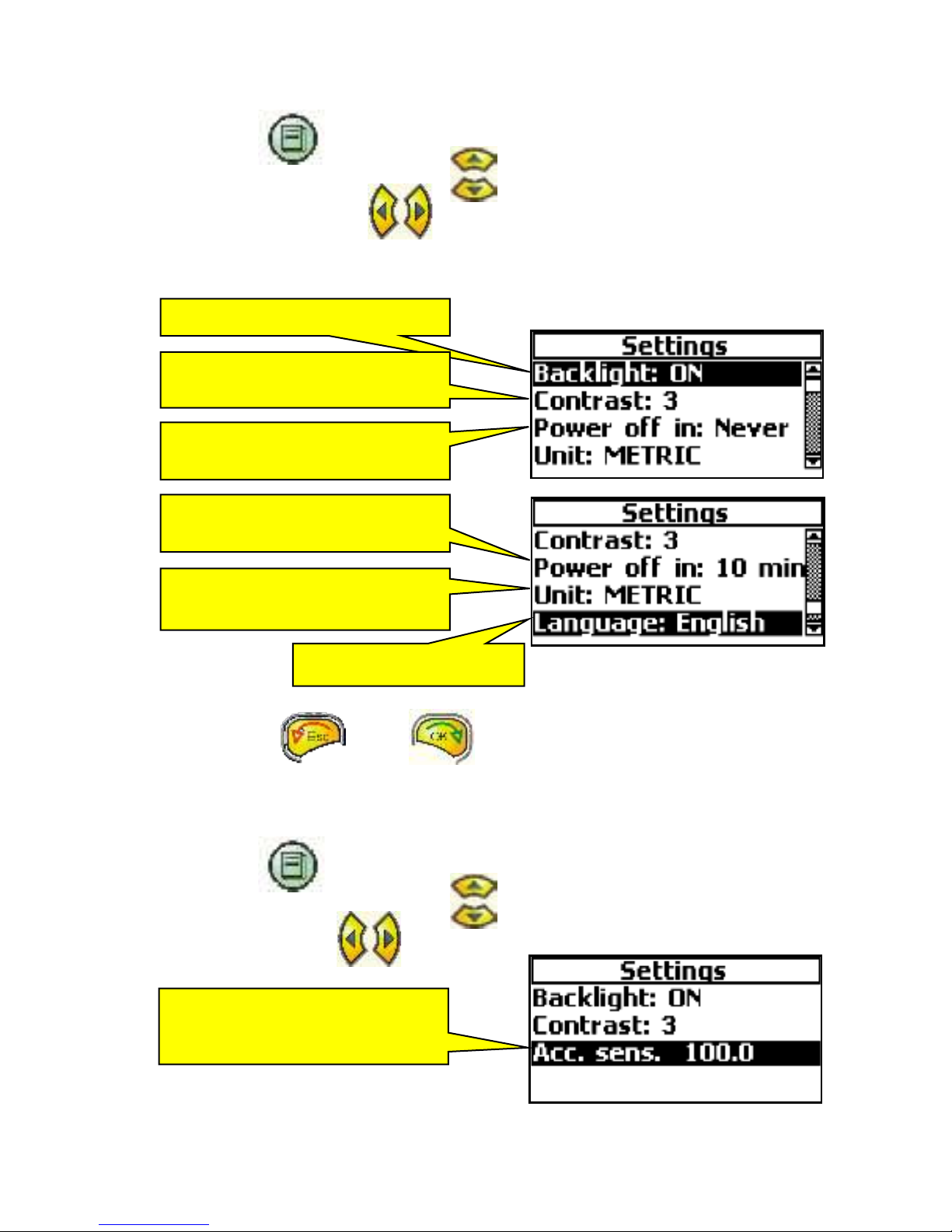
Press the Info button and this window will appear.
Move the line with the Up or the Down button to the function you want to change.
Press the Left or Right button to change the settings.
Turns the backlight ON or OFF
Changes the contrast ratio:
A low number gives a higher ratio.
Changes ON time of the
instrument
´The ON time can be changed
between 1, 3, 5, 10 min and Never.
Changes the units between Metric
and Imperial
Selects the language
Change the sensitivity mV/unit so it
corresponds to the connected
transducer sensitivity.
www.GlobalTestSupply.com
Find Quality Products Online at: sales@GlobalTestSupply.com

X-Viber manual
11
Total level
Move the line with the Up or
the Down button to Total
value.
Press the OK button and the
X-Viber starts to measure.
Press the Left or Right button to change the unit or average.
The list below shows available units.
Metric
Imperial
g rms
g rms
g Peak
g Peak
g P-P
g P-P
mm/s rms
in/s rms
mm/s Peak
in/s Peak
mm/s P-P
in/s P-P
m rms
mils rms
m Peak
mils Peak
m P-P
mils P-P
mm rms
thou rms
mm Peak
thou Peak
mm P-P
thou P-P
m/s rms
m/s Peak
m/s P-P
The instrument will automatically select the unit and average from the Settings menu.
This part of the
window shows the
actual vibration level.
This part of the
window shows the
present vibration unit.
This part of the window
shows the actual
frequency range.
The measured value
is compared with the
alarm level.
A happy face = below
A sad face = above
When this text is shown
the measurement is
temporally stopped.
www.GlobalTestSupply.com
Find Quality Products Online at: sales@GlobalTestSupply.com
X-Viber manual
12
Press the Up or Down button to change the frequency range.
The list below shows available frequency ranges.
Frequency range in Hz
2 to 800
4 to 1600
8 to 3200
10 to 6400
old ISO range 10 to 1000Hz
Press the AUX button to hold the measurement.
Press the AUX button again or the OK button to continue measuring.
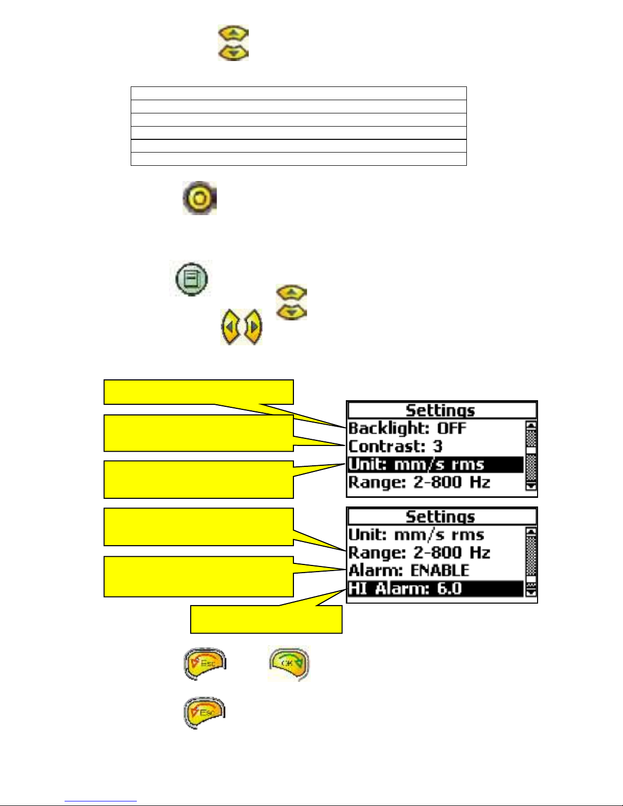
The Total value settings menu
Press the Info button and this window will appear.
Move the line with the Up or Down buttons to the function you want to change.
Press the Left or Right button to change the settings.
The settings in the Total value Settings menu will automatically be used when the Total
value window is opened the next time.
Press the ESC or OK button to exit to the Total level function.
Press the ESC button to leave the Total level function and go back to the
Measurement menu.
Turns the backlight ON or OFF
Changes the contrast ratio
A low number gives a higher ratio
Changes the vibration unit and
avreage
Changes the measured frequency
range
Enables or disables the alarm
face.
Changes the Alarm level
www.GlobalTestSupply.com
Find Quality Products Online at: sales@GlobalTestSupply.com
X-Viber manual
13
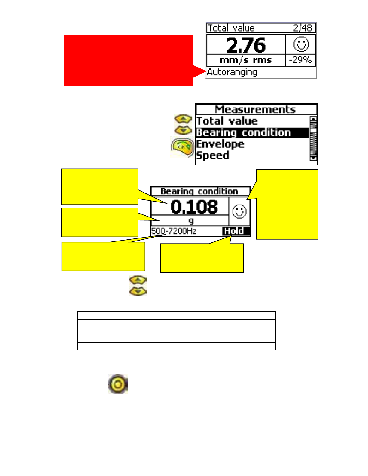
Bearing condition
Move the line with the Up or the
Down button to the Bearing
condition.
Press the OK button and the X-
Viber starts to measure.
Press the Up or Down button to change the frequency range.
The list below shows available frequency ranges.
Frequency range in Hz
500 to 7200
1000 to 7200
2000 to 7200
3000 to 7200
Use a low frequency range at slow rotating (below 600rpm) machines and a high
frequency range at high speed (above 6000rpm) machines.
Press the AUX button to hold the measurement.
Press the AUX button again or the Ok button to continue measuring.
This part of the
window shows the
actual bearing
condition value.
The unit g is the only
available unit for this
measurement.
This part of the window
shows the present
frequency range.
The measured
value is
compared with
the alarm level.
A happy face =
below
A sad face =
above
When this text is shown
the measurement is
temporally stopped.
Warning!
When the text “Autoranging”
appears, the measurement is
unstable. The operator must wait until
this message disappears before
using the measurement
www.GlobalTestSupply.com
Find Quality Products Online at: sales@GlobalTestSupply.com

X-Viber manual
14
Recommended bearing condition levels
Bearing condition value with the unit “g” RMS
Find the machine speed. Follow this line up to the judgment lines and read the value on
the left axis.
The diagram above is only a guide to interpret the bearing condition value. If vibrations of
other causes (e.g. flow surge, gear mesh) are within in the selected frequency range, this
can give a high bearing condition value without the bearing being damaged.
A high bearing condition value can also be acquired, if the bearing is poorly lubricated or is
overloaded (e.g. by misalignment, or large belt forces).
Compare this value with Envelope value and the bearing temperature. If all are high or
pointing upwards in the trend analysis you might have a bearing problem.
0,01
0,1
1
10
100
100 1000 10000
RPM
2000
3000
400
6000
4000
500
Good
Acceptable
Fair
Failing
Replace
www.GlobalTestSupply.com
Find Quality Products Online at: sales@GlobalTestSupply.com
X-Viber manual
15
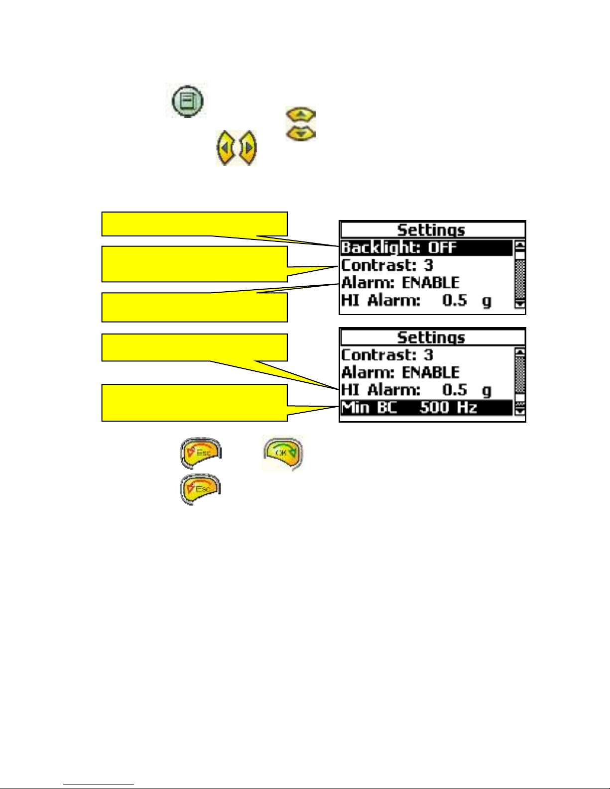
Bearing condition settings menu
Press the Info button and this window will appear.
Move the line with the Up or the Down button to the function you want to change.
Press the Left or Right button to change the settings.
The settings in the Bearing condition Settings menu will automatically be used, when the
Bearing condition window is opened the next time.
Press the ESC or OK button to exit to the Bearing settings menu.
Press the ESC button to leave the Bearing condition function and go back to
the Main menu.
Turns the backlight ON or OFF
Changes the contrast ratio
A low number gives a higher ratio.
Changes the measured frequency
range
Enables or disables the alarm face
Changes the Alarm level
www.GlobalTestSupply.com
Find Quality Products Online at: sales@GlobalTestSupply.com
Other manuals for X-Viber
1
This manual suits for next models
1
Table of contents
Other VMI Measuring Instrument manuals


