VMI VIBER X3 User manual

Vibraon Measurement Instruments
Manual Ver. 2.9
Refers to VIBER X3™ rev: 1.6-1.7
Soware 4.7-4.8
VIBER X3™
VIBER X3™
Manual
Ver. 2.5


Vibraon Measurement Instruments
Index
1 Important information 3
2 Introduction 4
3 Scope of supply 5
4 Instrument keypad and LED´s 6
5 Setting Menu and Functions 7
6 Screen descriptions 8
7 Warning messages 14
8 How to interpret vibration levels 15
9 Vibration analysis 17
10 Balancing with VIBER X3™ 21
11 Trend View soware 30
Technical data VIBER X3™ 52
Vibraon Measurement Instruments
2
Vibraon Measurement Instruments
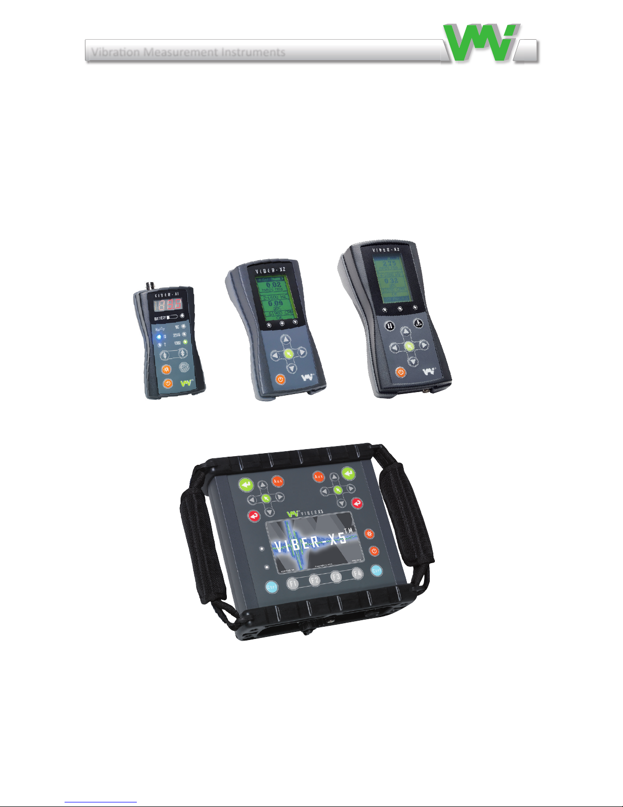
Our X series of hand-held instrument
VIBER X1 VIBER X2 VIBER X3
VIBER X5
Manual Viber X1_121002.indd 2 10/3/12 9:26 AM
VIBER X1™VIBER X2™VIBER X3™
VIBER X5™
Our x-series of hand-held instrument

Vibraon Measurement Instruments
3
1 Important information
Safety precautions
Vibration measurement and balancing involves measurement on rotating
machines. Keep a safe distance to rotating parts and secure transducers and
transducer cables from rotating parts. Always follow internal, local and na-
tional security regulations! When working with weights on the rotor always
secure the start switch with a locker and also use the emergency switch for
double safety. This is especially important when the machine is remote con-
trolled.
VMI takes no responsibility for any accidents on people and machines.
VMI and our authorized dealers will take no responsibility for damages on
machines and plants as the result of the use of VIBER X3™ measurements.
VMI has the aim to improve and develop our products, why surely an up-
graded version of this manual will be distributed in the future. As a result of
this, we might change and correct these items in later issues without further
notice. Also changes in the VIBER X3™ equipment may take place that
affect the accuracy of the information.

Vibraon Measurement Instruments
4
2 Introduction
VIBER X3™ is designed for maintenance/repairer and operators personnel. It is an excellent
tool, for basic condition monitoring checks, easy to use and reliable for status analyse. The VI-
BER X3™ instrument has the following features:
• Accuratemeasurementsin4selectablefrequencyranges.
Gives higher reliability.
• Real-timemeasurementofthetotalvibrationlevelandtheBearing
Condition(BC),measuresanddisplayedsimultaneously,facilitate
analysisofBearingfaults.
• HeadphonesetwithvolumecontrolandhighpasslterforBearingnoise detection.
CanbeusedwithoutBCmeasuringandtrending,tosavetime.Usesiftherearemany
smallBearingsasinprintingmachinesorconveyorsandsimilarapplications.
• ListeningtobearingsoundwhilecomparingthedisplayedBCvalue.
• Fastandeasyfaultanalysisscreendisplayingthevehighestpeaks
with amplitude and frequency one by one.
• Measurementunitsandmeasurementpresentationmaybeselectedby
the user from the following list:
•g-value=(RMS,PeakorPeak-Peak)
•a=m/s2(RMS,PeakorPeak-Peak)
•V=mm/sec(RMS,PeakorPeak-Peak)
•V=inch/sec(RMS,PeakorPeak-Peak)
•D=mils(RMS,PeakorPeak-Peak)
•D=μm(RMS,PeakorPeak-Peak)
•
BearingConditionmeasurementsinawidefrequencyrange(0,5-16kHz).
• Built-ininfraredtemperaturesensor,unitsin°Cor°F.
• Barindicatorshowsmeasurementstability.
•
Vibration,temperatureanddangeralarmsbyredandyellowcolourLED’s.
• Fastbatterychargingcapacityusinganexternalcharger,providedinthe delivery.
• Displaywithbacklight.
• AdjustableAuto-shutoffforenergysaving.
• Dustandwaterproof,forroughuse(IP65).

Vibraon Measurement Instruments
5
A complete delivery is:
• VIBERX3™, machine condition analyzer
• Ahighperformanceaccelerometer
• 1mtransducercable
•Extensiontip,magnet
• Batterycharger
• Headphones
• Datastoragewith“VMITrendView”software,installation
instructions and user manual
• Printedmanualforinstrumentandsoftware
All this together are available in a sturdy, airtight, chemical resistant,
dust-andwaterproofIP68case.
3 Scope of supply
Vibraon Measurement Instruments
6
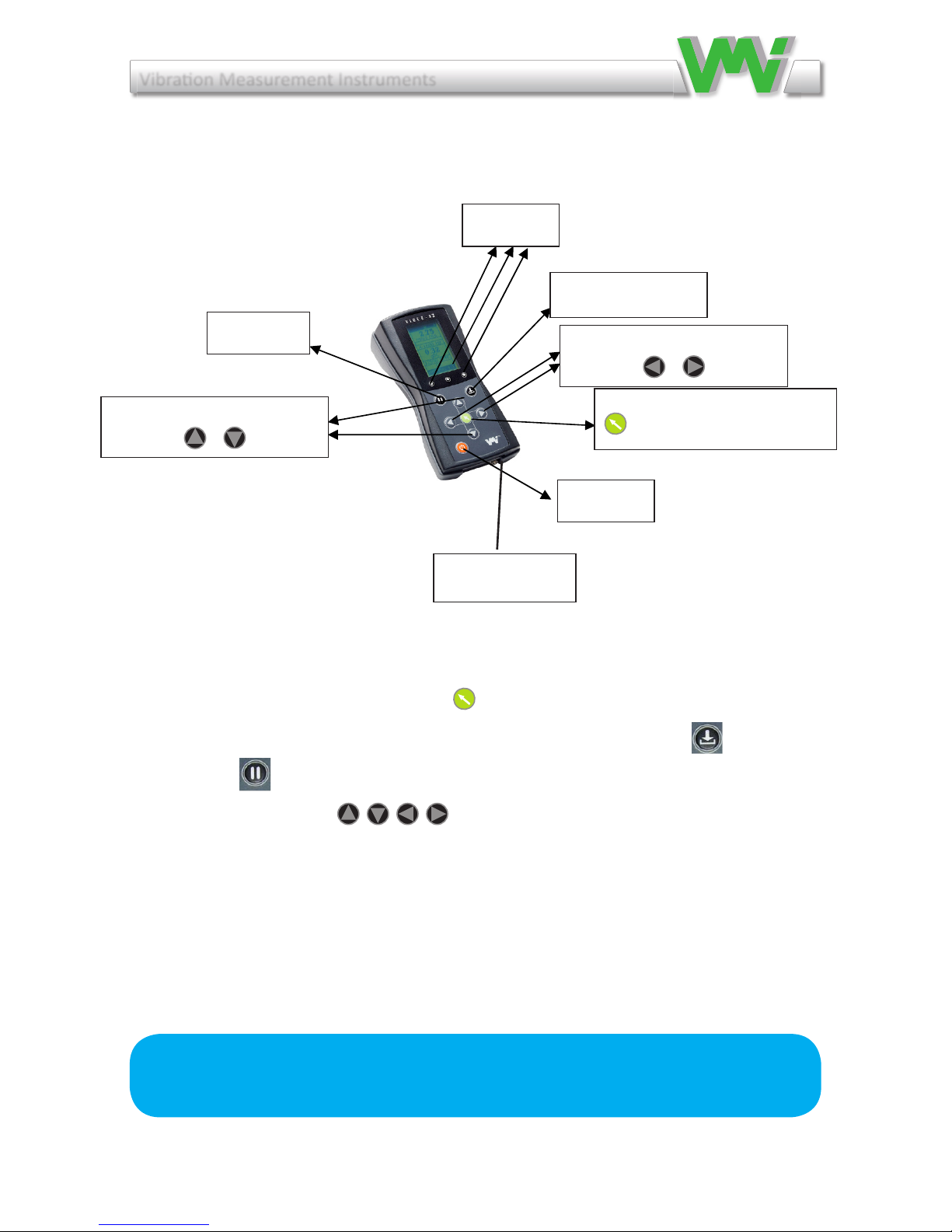
The VIBER X3™ keypad
1ON/OFFOrangekey
1MENUandACCEPTGreenkey
1HoldforSAVEkeyforRouteandBalancingmeasurements
1Holdkey
4Arrowwhitekeys
1GreenLEDlights,whenanykeyispressed.
1YellowLEDlights,whenthemeasurementisabovethewarningsetlevel.
1RedLEDlights,whenthemeasurementisabovethedangersetlevel.
3
Scope of supply
A complete delivery is:
• Viber X3™, machine condition analyzer
• A high performance accelerometer
• 1 m transducer cable
• Extension tip
• Battery charger
• Head phones
All this together are available in a sturdy, airtight, chemical resistant, dust- and waterproof IP68 case.
Instrument keypad and LED’s
The VIBER X3
™ keypad
1 ON/OFF Orange key
1 MENU and ACCEPT Green key
1 Save key for Route measurement or Balancing measurements
1 Hold key
4 Arrow white keys
3 Leds*
Green LED lights, when any key is pressed.
Yellow LED lights, when the measurement is above the warning set level.
Red LED lights, when the measurement is above the danger set level.
LED’s
SAVE key
Right and left Arrow key
ON/OFF
MENU and ACCEPT
Green
key
Up and
D
own Arrow key
HOLD key
NOTE: As default, when the instrument starts, the transducer power is
ENABLED
4 Instrument keypad and LED´s
Hold for SAVE key
LED´s
HOLD key
ON/OFF
Right and left Arrow key
MENU and ACCEPT
Green key
Up and down Arrow key
Signal and
headphone jack
◀

Vibraon Measurement Instruments
7
5 Setting Menu and Functions
IntheFunctionandSettingMenuyoucansetorchoosemenusorfunctions
byusingArrowsandgreenButtonfornavigation.
1. Vibration: Green button choose to measure vibration
2. Temperature: Green button choose to measure Temperature
3. Audio: Green button choose to open Audio mode, make start of liste
ning possible, default is enabled.
4. Balancing:Greenbuttonchoosebalancing,chooseaneworanOngoing
5. Settings:Useformakesettingsforthefunctions:
•Instrument,Backlighton/off,Auto-shutoff,Language(Imple
mentedlanguagesare:English,Swedish,French,German,Romanian,
Czech,Spanish,PortugueseandFinnish).
•Transducer,sensorsensitivityandpowerOn/Off
•Vibration,SetlevelandenableordisableAlarm,Warning,Unitsdisplayed
•Temperature,Unit,Emissivity,setlevelandenableordisableAlarm,
Warning
•Audio,FilterOn/off,Soundenableordisable
6. Upload: Choose to upload saved measurements and balancing results
7. Delete:Usedtoremovestoredmeasurements.
ToremoveonemeasurementfromtheVIBERX3™memorylist:usethe
”Hold for Save”button.Thefunction”delete”inthemenufordeletion
canalsobeusedtoviewstoredmeasurementsinVIBERX3™memeory
list,exitfromthememorylistwiththe”Hold for Save”button.
Functions
Vibration
Temperature
Audio
Balancing
Settings
Upload
Delete
Delete
Clear mem.
ALL vib.
ALL temp.
ALL bal.
Vibration
Temperature
Balancing
BACK

Vibraon Measurement Instruments
8
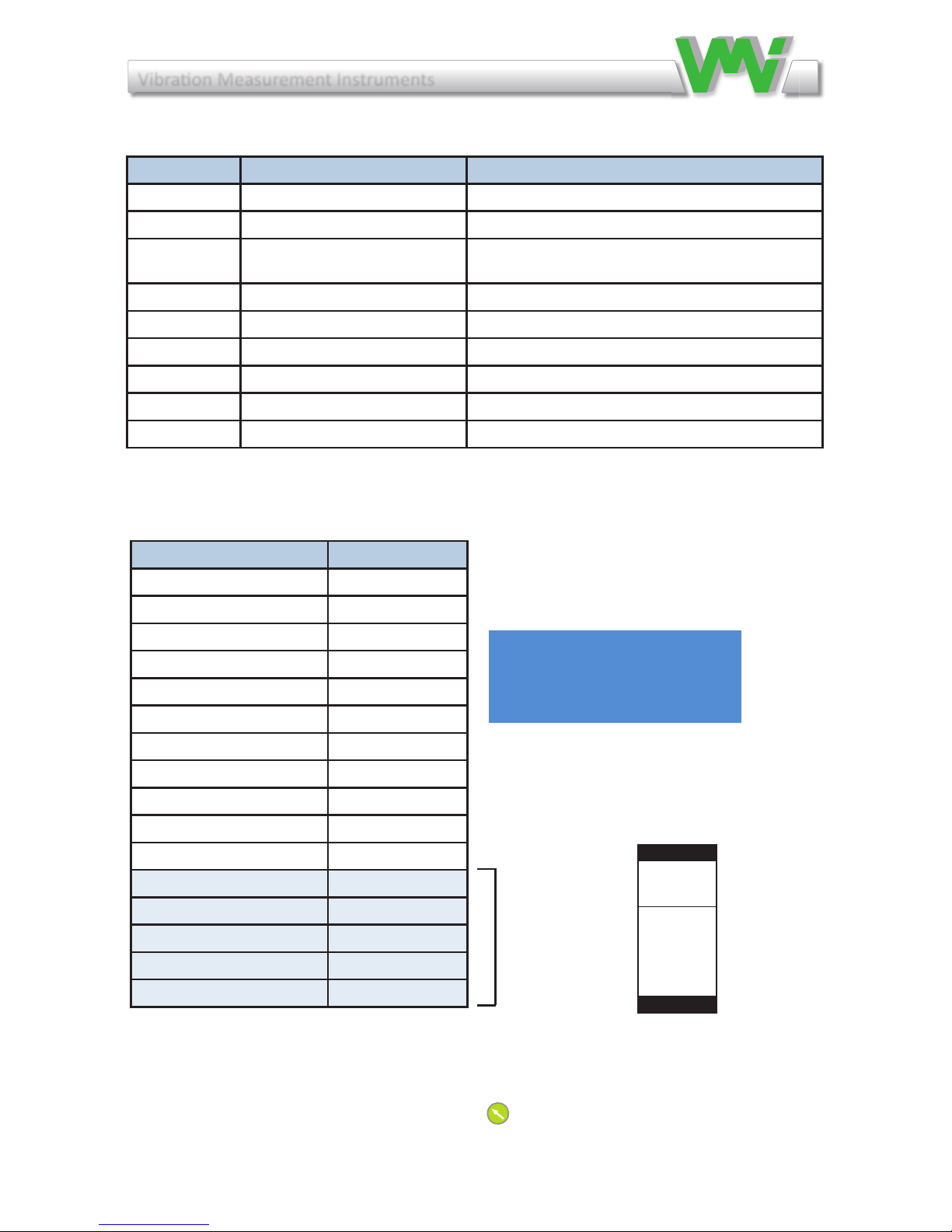
6 Screen descriptions
6.1 Analysis measurement screen
In the analysis screen you are able to see the total value as well as the amplitude and
frequencyofthevehighestpeaksinthespectrumrange.Ifyouhaveenabledthe
audio(seeaudioscreen)youmayalsoatthesametimelistentothebearings.
In the upper right corner you will see the battery status and if the charger is plugged
in or not.
Measurement status can be one of following:
- Measuring(Vibrationmeasuringisongoing)
- Autoranging(Theinstrumentiscalculatingthebestmeasurementlevelrange)
- Averaging(Averagingofthemeasureddata)
- OK(Themeasurementisstable)
-Overow (The signal is too high – the measurement is incorrect/not readable.)
Incaseofamplitudeoutofrange,thevalueisshownas3stars(***).
Whenthemeasurementisstable,thelastmessagelineshowsOK.
5
1Analysis measurement screen
In the analysis screen you are able to see the total value as well as the amplitude and frequency of the five first peaks
in the spectrum range. If you have enabled the audio (see audio screen) you may also at the same time listen to the
bearings.
In the upper right corner you will see the battery status and if the charger is plugged in or not.
Measurement status can be one of following:
- Measuring (Vibration measuring is ongoing)
- Ranging (The instrument is calculating the best measurement range)
- Averaging (Averaging of the measured data)
- OK (The measurement is stable)
- Overflow (The signal is too high –the measurement is incorrect/not readable.)
In case of amplitude out of range, the value is shown as 3 stars (***).
When the measurement is stable, the last message line shows OK.
The Frequency range of the peaks in relation to the frequency range setting is described in the below table, the limit
of the maximum frequency of the peak is 1 000 Hz or 60 000 CPM.
Frequency range
Frequency range of the peaks
2 to 1600 Hz
120 to CPM
4 to 1000 Hz
240 to 60000 CPM
4-3200 Hz
CPM
8 to 1000 Hz
480 to 60000 CPM
10-1000 Hz
CPM
10 to 1000 Hz
600 to 60000 CPM
When pressing the (UP) or (DOWN) arrow keys, in the Vibration Screen, the measuring unit is temporarily
changed.
When the (MENU) key is pressed, the Analysis Settings menu is shown.
Select an item with the (UP) and (DOWN) arrow keys.
Change the settings of the selected item with the (LEFT) and (RIGHT) arrow keys.
Auto-shutoff
DISABLED
Settings
20 sec.
Unit
mm/s rms
Range
2-1600 Hz
To exit Settingsmenu, just press again the (MENU) key.
All settings, except disabled transducer power, will be stored into the permanent FRAM memory.
NOTE: As default, when the instrument starts, the transducer power is ENABLED.
Selected item
Frequency /CPM
Measurement status
Total value
measurements
presentat
Measurement Stability bar
Frequency range
Peak number
Indicates battery status and if it is charging
Amplitude
Indicates battery status and if it is charging
Total value
Measurment Stability bar
Frequency range
Peak number
Amplitude
Frequency /RPM
Measurment status
If alarm is activated levels will be displayed if not **** are displayed

Vibraon Measurement Instruments
9
The following item settings are available:
The frequency appears as follows:
Frequency range Frequency range of peak detecon
2 - 400 Hz 2 - 400 Hz
6 - 1600 Hz 6 - 1600 Hz
11 - 3200 Hz 11 - 2000 Hz
10 - 1000 Hz 10 - 1000 Hz
Item Value Notes
Backlight ENABLED or DISABLED
Auto-shuto ENABLED or DISABLED Shuto aer 60 seconds
Seng 20 sec, 30 sec, 40 sec, 1 min, 2 min
and 3 min Set the Auto-shuto
Unit
g (RMS, Peak or P-P)
m/s2 (RMS, Peak or P-P)
mm/s (RMS, Peak or P-P)
µm (RMS, Peak or P-P)
inch/sec (RMS, Peak or P-P)
mils (RMS, Peak or P-P)
Range
2 - 400 Hz
6 - 1600 Hz
11 - 3200 Hz
10 - 1000 Hz
Alarm * ENABLED or DISABLED
Warning Default value 6.00 Keep key pressed to auto-repeat
Danger Default value 11.0 Keep key pressed to auto-repeat
Language ** (Depending of rmware version)
Sensivity (mV/g)
During calibraon the transducer
sensivity can be adjusted between
0,1 to 99999 mV/g
Do not change aer instrument cali-
braon. Set sensivity in accordance
with the transducers
Transducer power ENABLED or DISABLED 4 mA for accelerometer
Frequency RPM or Hz
* Can only be set for units mm/s and in/s RMS
** Standard languages are: English, Swedish, French, German, Czech, Romanian, Spanish, Portuguese and
Finnish. For another language please contact your instrument supplier for avaliability

Vibraon Measurement Instruments
10
2
Warning!
Incorrect setting of the emissivity factor
can lead to considerable errors of
measured temperature.
Direct the IR temperature transducer towards the surface you want to measure. Keep a distance of approximately 200-500 mm (8- 20 inches)
between the instrument and the object. Reduce the distance between the object and the instrument in accordance with the surface size.
Note: when you get the temperature that differs most to the surroundings, then you probably have got the right direction.
The measurement surface size related to the distance 8:1
Emissivity:
Set the coefficient for surface reflection factor (Emissivity factor) using the table below or check via a contact probe.
Select the item with (UP) and (DOWN) arrow keys.
Sound screen
Listening to a machine sounds enables analysis of gears and low speed bearings (<300 rpm) in an alternative way and can improve analysis
speed and quality. Viber X3™ makes it possible for the user to listen to the machine while at the same time seeing the vibrations in the
instrument display.
Note that you must choose the Vibration Screen while the sound is enabled the see the vibration signal.
When a headphone set is connected to the Viber X3™, the Sound Screen can be used to adjust the sound volume (depending on hardware
version there is also a volume control on the headphone cord). Before changing volume, the SOUND function must be ON. Sound output
status is enabled (ON) or disabled (OFF) in the Sound Settings menu.
Material
Emissivity
factor
Heat sink, black anodized
0.98
Paper
0.97
Black paint, matt
0.97
Ice, smooth
0.97
Wood
0.94
Glass
0.94
Rubber, hard
0.94
Transformer paint
0.94
Concrete
0.93
Br
ick, mortar, plaster
0.93
Porcelain
0.92
Steel, oxidized
0.79
Cooper, oxidized
0.76
Steel, heat treated surface
0.52
Copper
0.04
Aluminium, bright
0.04
Warning!
To protect your hearing, you should always remove the headphones from your
ears when you move the sensor or re
-
connect the cable.
6.2 Temperature measurement screen
Inthetemperaturescreenyouseethetemperatureoftheobjectyouare
measuring.
Temperature measurement status can be one of following:
Averaging(Averagingofthemeasureddata)
OK(Themeasurementisstable)
Overow
(Thesignalistoohigh–themeasurementisincorrect/notreadable.)
Incaseofamplitudeoutofrange,thevalueisshownas3stars(***).
Whenthemeasurementisstable,thelastmessagelineshowsOK.
AvailablemeasurementunitsareCelsius(°C)andFahrenheit(°F).
DirecttheIRtemperaturetransducertowardsthesurfaceyouwanttomea-
sure. Keep a distance of approximately 200-500 mm (8- 20 inches)
betweentheinstrumentandtheobject.Reducethedistancebetweenthe
objectandtheinstrumentinaccordancewiththesurfacesize.
Note:whenyougetthetemperaturethatdiffersmosttothesurroundings,
then you probably have got the right direction.
Auto-shutoff
DISABLED
Settings
20 sec.
Unit
mm/s rms
Range
2-1600 Hz
To exit Settings menu, just press again the (MENU) key.
All settings, except disabled transducer power, will be stored into the permanent FRAM memory.
1.1 Temperature measurement screen
In the analysis screen you see the temperature of the object you are measuring. If you have enabled the audio (see audio screen) you may also
at the same time listen to the bearings.
In the upper right corner you will see the battery status and if the charger is plugged in or not.
Temperature measurement status can be one of following:
Ranging (The instrument is calculating the best measurement range)
Averaging (Averaging of the measured data)
OK (The measurement is stable)
Overflow (The signal is too high – the measurement is incorrect/not readable.)
In case of amplitude out of range, the value is shown as 3 stars (***).
When the measurement is stable, the last message line shows OK.
Available measurement units are Celsius (°C) and Fahrenheit (°F).
Stability bar
Temperature
Current emissivity factor
Measurement status
NOTE: As default, when the i
nstrument starts, the transducer power is ENABLED.
Selected item
Themeasurementsurfacesizerelatedtothedistance8:1
When(MENU)keyispressed,theTemperatureSettingsmenu is shown.
Vibraon Measurement Instruments
11
2
Warning!
Incorrect setting of the emissivity factor
can lead to considerable errors of
measured temperature.
Direct the IR temperature transducer towards the surface you want to measure. Keep a distance of approximately 200-500 mm (8- 20 inches)
between the instrument and the object. Reduce the distance between the object and the instrument in accordance with the surface size.
Note: when you get the temperature that differs most to the surroundings, then you probably have got the right direction.
The measurement surface size related to the distance 8:1
Emissivity:
Set the coefficient for surface reflection factor (Emissivity factor) using the table below or check via a contact probe.
Select the item with (UP) and (DOWN) arrow keys.
Sound screen
Listening to a machine sounds enables analysis of gears and low speed bearings (<300 rpm) in an alternative way and can improve analysis
speed and quality. Viber X3™ makes it possible for the user to listen to the machine while at the same time seeing the vibrations in the
instrument display.
Note that you must choose the Vibration Screen while the sound is enabled the see the vibration signal.
When a headphone set is connected to the Viber X3™, the Sound Screen can be used to adjust the sound volume (depending on hardware
version there is also a volume control on the headphone cord). Before changing volume, the SOUND function must be ON. Sound output
status is enabled (ON) or disabled (OFF) in the Sound Settings menu.
Material
Emissivity
factor
Heat sink, black anodized
0.98
Paper
0.97
Black paint, matt
0.97
Ice, smooth
0.97
Wood
0.94
Glass
0.94
Rubber, hard
0.94
Transformer paint
0.94
Concrete
0.93
Br
ick, mortar, plaster
0.93
Porcelain
0.92
Steel, oxidized
0.79
Cooper, oxidized
0.76
Steel, heat treated surface
0.52
Copper
0.04
Aluminium, bright
0.04
Warning!
To protect your hearing, you should always remove the headphones from your
ears when you move the sensor or re
-
connect the cable.
Emissivity:
Setthecoefcientforsurfacereectionfactor(Emissivityfactor)usingthetable
below or check via a contact probe.
The following temperature settings are possible:
ToexitSettingsmenu,justpressagainthe(MENU)key.All settings will be
storedintothepermanentFRAMmemory.
To change Emissivity factor, in the Function menu go to Settings then go to
Temp scroll down to Emissivity and use the arrow keys to change the value.
Temp
°C
Emissivity
0,98
Alarm
DISABLED
Warning
60,0 °C
Danger
80,0 °C
ACCEPT
Item Values Set the Auto-shuto me
Backlight ENABLED or DISABLED
Auto-shuto ENABLED or DISABLED
Seng 20 sec, 30 sec, 40 sec, 1 min,
2 min, 3 min Set the Auto-shuto me
Unit °C or °F
Alarm ENABLED or DISABLED
Warning 0,00 - X Keep key pressed to auto-repeat
Danger 0,00 - X Keep key pressed to auto-repeat
Language If nothing else is specied at order English will be pre set
Emissivity 0,79 - 1,00 Should be set in accordance with the target surface
Material Emissivity factor
Heat, sink, black anodized 0.98
Paper 0.97
Black paint, ma 0.97
Ice, smooth 0.97
Wood 0.94
Glass 0.94
Rubber, hard 0.94
Transformer paint 0.94
Concrete 0.93
Brick, mortar, plaster 0.93
Porselain 0.92
Steel, oxidized 0.79
Copper, oxidized 0.76
Steel, heat treated surface 0.52
Copper 0.04
Aluminium, bright 0.04
Don’t use

Vibraon Measurement Instruments
12
6.3 Sound screen
Listeningtomachinesoundsenablesanalysisofgearsandlowspeedbearings(<300
RPM)inanalternativewayandcanimproveanalysisspeedandquality.
VIBER X3™ makes it possible for the user to listen to the machine while at the
same time seeing the vibrations in the instrument display.
NotethatyoumustchoosetheVibrationScreenwhilethesoundisenabledto see
the vibration signal.
When a headphone set is connected to the VIBER X3™, the Sound Screen can
beusedtoadjustthesoundvolume(dependingonhardwareversionthereisalso
avolume control ontheheadphone cord).Beforechanging volume, theSOUND
functionmustbeON.Soundoutputstatus is enabled (ON) or disabled (OFF) in
the Sound Settings menu.
Warning!
To protect your hearing, you should always remove the headphones from
your ears when you move the sensor or re-connect the cable.
2
NY BILD MED BACK
Filter:
When the filter status is set to YES a high pass filter is activated enabling the user to only listen to machine noise in high frequencies.
Audio:
When Audio is ON, using the (UP) and (DOWN) arrows, the sound level can be adjusted. To do this, press and keep the (UP) or
(DOWN) arrow pressed. The volume will increase/decrease slowly. Depending on hardware version the headphone set can also be equipped
with a volume control on the cord.
As safety precautions and to save battery the audio settings are always reset, turning the audio off, when the instrument is started.
When the (MENU) key is pressed, the Sound Settings menu is shown.
Settings
Backlight
ENABLED
Auto-shutoff
DISABLED
Settings
20 sec.
HP Filter
ON
1.2 Balancing screen
If you choose in the function menu, balancing.
Selected
item
Note: With a headphone inserted, at the
maximum volume level, the power
consumption will increase with 150 mA. To
save the battery power, turn the audio off
when it is not used. When the battery
voltage is beginning to be too low and
headphone set is plugged-in, the instrument
will be automatically reset. When the
instrument is reset, as default, the sound is
disabled. In this way the instrument can
continue to run for a while longer without
the need of charging the batteries.
Sound volume
Filter status
Sound status
Filter:
WhenthelterstatusissettoYESahighpasslterisactivatedenablingtheuserto
only listen to machine noise in high frequencies.
Audio:
WhenAudioisON,usingthe(LEFT)and(RIGHT)arrows,thesoundlevel
canbeadjusted.Todothis,pressandkeeptheLEFTortheRIGHT arrow
key pressed. The volume will increase/decrease slowly.
Dependingonhardwareversiontheheadphonesetcanalsobeequipped
with a volume control on the cord.
As safety precautions and to save battery the audio settings are always reset, turning
the audio off, when the instrument is started.
Whenthe(MENU)keyispressed,theSoundSettingsmenuisshown.
2
NY BILD MED BACK
Filter:
When the filter status is set to YES a high pass filter is activated enabling the user to only listen to machine noise in high frequencies.
Audio:
When Audio is ON, using the (UP) and (DOWN) arrows, the sound level can be adjusted. To do this, press and keep the (UP) or
(DOWN) arrow pressed. The volume will increase/decrease slowly. Depending on hardware version the headphone set can also be equipped
with a volume control on the cord.
As safety precautions and to save battery the audio settings are always reset, turning the audio off, when the instrument is started.
When the (MENU) key is pressed, the Sound Settings menu is shown.
Settings
Backlight
ENABLED
Auto-shutoff
DISABLED
Settings
20 sec.
HP Filter
ON
1.2 Balancing screen
If you choose in the function menu, balancing.
Selected
item
Note: With a headphone inserted, at the
maximum volume level, the power
consumption will increase with 150 mA. To
save the battery power, turn the audio off
when it is not used. When the battery
voltage is beginning to be too low and
headphone set is plugged-in, the instrument
will be automatically reset. When the
instrument is reset, as default, the sound is
disabled. In this way the instrument can
continue to run for a while longer without
the need of charging the batteries.
Sound volume
Filter status
Sound status
Settings
Instrument
Transducer
Vibration
Temp
Audio
BACK

Vibraon Measurement Instruments
13
Note: With a headphone inserted, at
the maximum volume level, the power
consump on will increase with 150
mA. To save the ba ery power, turn the
audio o when it is not used. When the
ba ery voltage is beginning to be too
low and headphone set is plugged-in,
the instrument will be automa cally
reset. When the instrument is reset,
as default, the sound is disabled. In
this way the instrument can con nue
to run for a while longer without the
need of charging the ba eries.
Notera: Med hörlurarna isatta är den maximala volymnivån
150 mA. Stäng av ljudet när det inte används för att spara
batteri.

Vibraon Measurement Instruments
14
7 Warning messages
The following message may appear in normal operation:
Warning messages
The following message may appear in normal operation:
This message may appear if the calibration data is lost from the permanent FRAM memory or if the calibration data are
corrupted.
In such cases, the instrument must be re-calibrated; otherwise it will measure incorrectly. The message appears only
once, and then default calibration data is used.
When this message appears, the battery voltage is too low to ensure a correct running condition. The measurements may
be invalid! The instrument battery pack must be charged immediately, using the external charger. In order to temporarily
decrease the power consumption, the backlight will be switched OFF. The instrument can still work, but only for a short
while. If even in this condition the voltage remains low, the instrument will shut off in 20 sec.
This message appears only if the Auto-shut off setting is enabled. The user may cancel the shut-off condition, pressing any
key except ON/OFF. If no key is pressed the instrument will shut off in 5 seconds.
This message appears only if the Transducer power setting is enabled and indicates that the
transducer is missing or is out of order.
When the Transducer power setting is disabled, the user has the possibility to use another external source for the vibration input (a signal
generator or a buffered output from another device).
When the instrument starts, the Transducer power setting is always ENABLED. When this message appears, it will remain on the screen, even
if the transducer is plugged-in. To continue the normal running mode in such a condition, switch the screen temporarily to another menu.
When you come back, the message disappears.
2 Battery status bar
In every measurement screen, at the upper side, a battery status bar is shown.
The status bar indicates the battery voltage, as follows:
External charger plugged into the instrument. Battery is charging.
If the charger is removed, the status bar shows the remaining battery voltage:
When the voltage exceeds 4.0 V, the battery status bar indicates full battery.
If the battery voltage drops to less than 3.5 V, the instrument will shut-off in 20 sec.
Lift the battery cover by removing the two screws on the back side of the instrument.
This message may appear if the calibration data is lost
fromthepermanentFRAMmemoryorifthecalibration
data are corrupted. In such cases, the instrument must be
re-calibrated; otherwise it will measure incorrectly. The
message appears only once, and then default calibration
data is used.
When this message appears, the battery voltage is too
low to ensure a correct running condition. The measure-
ments may be invalid! The instrument battery pack must
be charged immediately, using the external charger. In or-
der to temporarily decrease the power consumption, the
backlightwillbeswitchedOFF.Theinstrumentcanstill
work, but only for a short while. If even in this condition
thevoltageremainslow,theinstrumentwillshutoffin20
sec.Batterychargeshouldnotbeterminatedbeforethe
greenLEDlighthasgoneout.
This message appears only if the Auto-shut off setting
is enabled. The user may cancel the shut-off condition,
pressinganykeyexceptON/OFF.Ifnokeyispressedthe
instrumentwillshutoffin5seconds.
This message appears only if you have forgot to connect
the transducer, or if transducer is broken.
When the Transducer power setting is disabled, the user has the possibility
to use another external source for the vibration input (a signal generator or a
bufferedoutputfromanotherdevice).
Whentheinstrumentstarts,theTransducerpowersettingisalwaysENAB-
LED.Whenthismessageappears,itwillremainonthescreen,evenifthe
transducer is plugged-in. To continue the normal running mode in such a
condition, switch the screen temporarily to another menu.
When you come back, the message disappears.
Warning messages
The following message may appear in normal operation:
This message may appear if the calibration data is lost from the permanent FRAM memory or if the calibration data are
corrupted.
In such cases, the instrument must be re-calibrated; otherwise it will measure incorrectly. The message appears only
once, and then default calibration data is used.
When this message appears, the battery voltage is too low to ensure a correct running condition. The measurements may
be invalid! The instrument battery pack must be charged immediately, using the external charger. In order to temporarily
decrease the power consumption, the backlight will be switched OFF. The instrument can still work, but only for a short
while. If even in this condition the voltage remains low, the instrument will shut off in 20 sec.
This message appears only if the Auto-shut off setting is enabled. The user may cancel the shut-off condition, pressing any
key except ON/OFF. If no key is pressed the instrument will shut off in 5 seconds.
This message appears only if the Transducer power setting is enabled and indicates that the
transducer is missing or is out of order.
When the Transducer power setting is disabled, the user has the possibility to use another external source for the vibration input (a signal
generator or a buffered output from another device).
When the instrument starts, the Transducer power setting is always ENABLED. When this message appears, it will remain on the screen, even
if the transducer is plugged-in. To continue the normal running mode in such a condition, switch the screen temporarily to another menu.
When you come back, the message disappears.
2 Battery status bar
In every measurement screen, at the upper side, a battery status bar is shown.
The status bar indicates the battery voltage, as follows:
External charger plugged into the instrument. Battery is charging.
If the charger is removed, the status bar shows the remaining battery voltage:
When the voltage exceeds 4.0 V, the battery status bar indicates full battery.
If the battery voltage drops to less than 3.5 V, the instrument will shut-off in 20 sec.
Lift the battery cover by removing the two screws on the back side of the instrument.

Vibraon Measurement Instruments
15
8Howtointerpretvibrationlevels
Auserwithnopreviousexperience,shouldusetheISO10816-3standard.
Thestandardnormallycallsforavelocitymeasurementinmm/sRMS.To
better understand what this measurement means, think of it as how fast the
machine is moving back and forth. This measure gives a good understanding
oftheamountof“breakdownenergy”,causingmainlywearandfatiguein
the machine or the structure.
The instrument measures the total RMS vibration value in the frequency
range.ThisRMSvalueistheaveragesumofallthemeasuredvibrations.
Example:
Ifthesimultaneousvibrationcausedbyunbalanceis(4mm/s),bymisalign-
ment(2mm/s)andbythegearmesh(5mm/s)thenthetotalvibrationmea-
sured with VIBER X3™is6.7mm/s.
Noticethatareductionoftheunbalancefrom4mm/sto1mm/s
willreducethetotalvaluefrom6,7mm/sto5,5mm/s.
Total vibraon(RMS)=√4*4+2*2+5*5=6,7mm/s
Vibraon Measurement Instruments
16
8.1 ISO standard 10816-3
TheISOstandard10816-3classiesmachinesdifferentlywhetherthemachi-
nesareconsideredasexibleorrigidmounted.Thisreectsthelocationof
the machines stiff-body resonances related to the basic running speed of the
machine.
Forinstance,amachinesupportedbyrubberorspring,haveresonancesat
low running speeds. The machine starts vibrate at certain low revolutions.
When the speed is increased above these resonance frequencies, the vibra-
tionisreduced.Thismachineisconsideredexible.
ModernmachinesthathavehighRPM’sandexiblebearingsupportsand
foundations,canbetreatedasexible,evenwhentheyaren’tmountedon
rubber or springs.
Group 1:
Largemachineswithratedpowerabove
300kW.Electricalmachineswithshaft
heightH>315mm.Operatingspeed
rangesfrom120to15000RPM.
Group 2:
Medium-sized machines with a rated
powerabove15kWuptoandincluding
300kW.Electricalmachineswithshaft
heightbetween160<H<315mm.
Operatingspeednormallyabove600RPM.
Group 3:
Pumpswithmultivaneimpellerandwithseparatedriverwithratedpower
above15kW.
Group 4:
Pumpswithmultivaneimpellerandwithintegrateddriverwithratedpower
above15kW.
2
3.1 ISO standard 10816-3
The ISO standard 10816-3 classifies machines differently whether the machines are considered as flexible or rigid
mounted. This reflects the location of the machines stiff-body resonances related to the basic running speed of the
machine.
For instance, a machine supported by rubber or spring, have resonances at low running speeds. The machine starts
vibrate at certain low revolutions. When the speed is increased above these resonance frequencies, the vibration is
reduced. This machine is considered flexible.
Modern machines that have high rpm’s and flexible
bearing supports and foundations, can be treated as
flexible, even when they aren’t mounted on rubber or
springs.
Group 1:
Large machines with rated power above 300kW.
Electrical machines with shaft height H > 315mm.
Operating speed ranges from 120 to 15000 rpm.
Group 2:
Medium-sized machines with a rated power above 15kW up to
and including 300kW.
Electrical machines with shaft height between
160 < H < 315 mm.
Operating speed normally above 600 rpm.
Group 3:
Pumps with multivane impeller and with separate driver with rated power above 15kW.
Group 4:
Pumps with multivane impeller and with integrated driver with rated power above 15kW.
4Vibration analysis
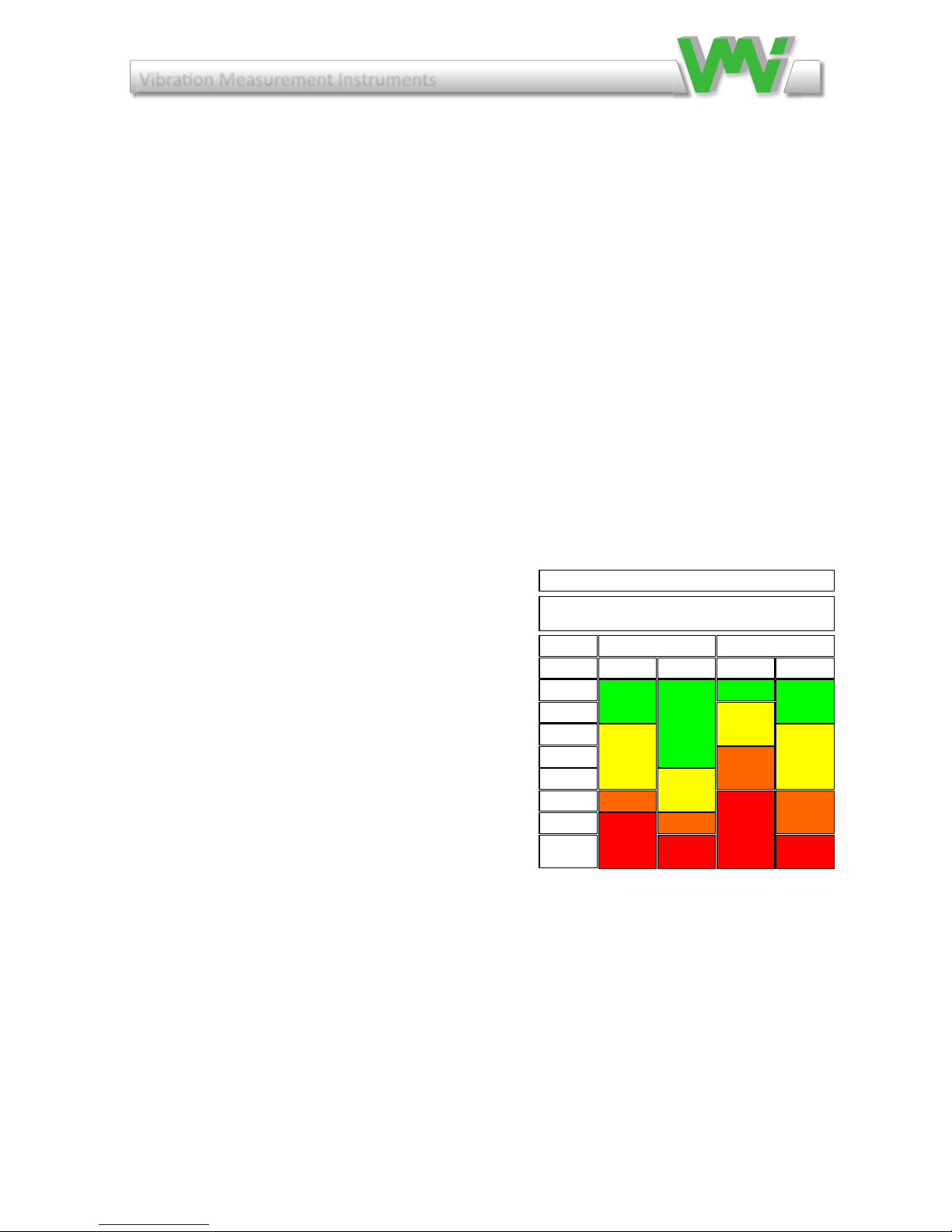
4.1 Recommended vibration levels in mm/s and common findings
The list and table below can be used, as a first consideration, when you approach a machine newly commissioned or after
some time in operation. Investigate the reason for any machine that vibrates above 3 mm/s RMS. Do not leave levels
above 7 mm/s without analyzing consequences.
0 –3 mm/s | 0 –0,12 in/s
Small vibrations - None or very small bearing wear. Rather low noise level.
3 –7 mm/s | 0,12 –0,28 in/s
Noticeable vibration levels often concentrated to some specific part as well as direction of the machine. Noticeable
bearing wear. Seal problems occur in pumps etc. Increased noise level; try to investigate the reason. Plan an action during
next regular stop. Keep the machine under observation and measure at shorter time intervals than before to detect a
deterioration trend if any. Compare vibrations to other operating variables.
7 –11 mm/s | 0,28 –0,43 in/s
Large vibrations. Bearings running hot. Bearing wear-out cause frequent replacements. Seals wear out, leakage of all
kinds evident. Cracks in welding and concrete foundations. Screws and bolts are loosening. High noise level. Plan action
soonest. Do your best to reveal the reason. You are wearing down investments quickly.
Rigid Flexible Rigid Flexible
Group 1 and 3 Group 2 and 4
Industrial machines with power above 15kW and
nominal speeds between120 -15000 r/min
mm/s
Unit
0-1.4
1.4-2.3
2.3-2.8
2.8-3.5
3.5-4.5
4.5-7.1
7.1-11
11--
Extraction's from ISO 10816-3

Vibraon Measurement Instruments
17
9 Vibration analysis
Recommendedvibrationlevelsinmm/sandcommonndings
The list and table on previous page can be used, as a rst consideration,
when you approach a machine newly commissioned or after some time in
operation.Investigatethereasonforanymachinethatvibratesabove3mm/s
RMS.Donotleavelevelsabove7mm/swithoutanalyzingconsequences.
0 – 3 mm/s | 0 – 0,12 in/s
Smallvibrations-Noneorverysmallbearingwear.Ratherlownoiselevel.
3 – 7 mm/s | 0,12 – 0,28 in/s
Noticeablevibrationlevelsoftenconcentratedtosomespecicpartaswell
asdirectionofthemachine.Noticeablebearingwear.Sealproblemsoccurin
pumpsetc.Increasednoiselevel;trytoinvestigatethereason.Plananaction
during next regular stop. Keep the machine under observation and measure
at shorter time intervals than before to detect a deterioration trend if any.
Compare vibrations to other operating variables.
7 – 11 mm/s | 0,28 – 0,43 in/s
Largevibrations.Bearingsrunninghot.Bearingwear-outcausefrequentre-
placements.Sealswearout,leakageofallkindsevident.Cracksinwelding
andconcretefoundations.Screwsandboltsareloosening.Highnoiselevel.
Planactionsoonest.Doyourbesttorevealthereason.Youarewearingdown
investments quickly.
11–mm/s|0,43−in/s
Very large vibrations and high noise levels. This is detrimental to the safe
operationofthemachine.Stopoperationiftechnicallyoreconomicallypos-
sibleconsideringtheplantstopcost.Noknownmachinewillwithstandthis
levelwithoutinternalorexternaldamage.Reduceanyfurtherrunningtime
to an absolute minimum.

Vibraon Measurement Instruments
18
9.1 Resonance
Aresonancecaneasilybefoundwhenaexiblemachineisrunningupor
downitsspeed.TheresonancefrequenciesarelocatedattheRPM’s,where
the vibration has a local maximum level.
To understand a resonance you can compare with the string of a guitar. The
string has its natural basic tone that will ring as soon as the string is struck.
The actual frequency of the tune depends on the stiffness and the distributed
mass of the string.
All machines have similar built in ”tones” with corresponding properties
consisting of stiffness and a mass in the form of mechanical strings such as
shafts,beams,oorsand in all mechanical parts. If anynaturalexcitation
(=alternatingforce)inthemachinehasthesameornearlythesamefrequen-
cyasaresonancefrequencythevibrationwillbeampliedinthismachine
part, and a much higher vibration level will occur.
To identify, measure the vibration levels in three perpendicular directions at
thebearings.Ifyoundameasurementwithatleastthreetimeshigherlevel
than in the other directions, consider resonance as a likely possibility. The
resonance is amplifying the mechanical force and thus gives a high vibration
in that direction. The resonance makes the machine unnecessarily sensitive
to mechanical forces.
Actions to handle a resonance are different depending on its location, opera-
ting conditions etc. It will normally require experience to alter the situation.
Onereasonisthatthemodicationcanaffectthebasicmechanicaldesign
of the machine and normally require the competence of a machine designer.
Werecommendhowevertoconsidersuchmodicationssincethechangeof
the resonance frequency normally is cheap compared to the high maintenan-
cecostthatwillfollowanyattempttorunamachineundertheinuenceof
a resonance.
Sometimesit´spossibletochangethespeedofmachines,whichoftenisa
simple solution.
Table of contents
Other VMI Measuring Instrument manuals


