VMI VIBER X4 User manual
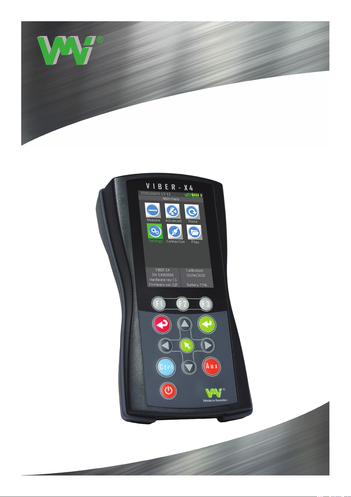
VIBER X4™
SMART PRODUCTS FOR SMART PEOPLE

Vibraon Measurement Instruments
2

Vibraon Measurement Instruments
Copyright© 2020 by VMI International AB. No copying or reproduction of this information may be un-
dertaken without written permission of VMI International AB. Due to continuous product development the
information in this document may be changed without further notice.
VMI International AB
Gottorpsgatan 5
SE-582 73 Linköping , Sweden
www.vmiab.com
Version: 1.01 Eng
Nov 2020
Instrument Manual
3

Vibraon Measurement Instruments
Table of Contents
Instrument basics
Connectors and sensors on front and rear
Main menu description
Instrument settings
General settings
Transducers
Select sensor, Update, Firmware, Pictures, Fonts
Language, Licenses, Factory reset, System information
Connection, Files
Exporting data in le menu
Route
Measuring in Route
Instrument Route Manager
Getting started with Measurements
Recommended Vibration Levels
ISO standard 10816-3
Measure (O Route)
Total Value
Spectra
Bearing Condition
Envelope
Phase
Speed
Temperature
Audio
Balancing
Waveform
Charging
Battery
Supplied items
Demo unit
Important information
Technical data
Declaration of Conformity
5
6
7
8-9
10
11
12
13
14
15
16
17
18
19-24
25
26
27-28
29
30-33
34-35
36-38
39
40
41
42
43-48
49-50
51
52
53
54
55
56
57
4
Vibraon Measurement Instruments
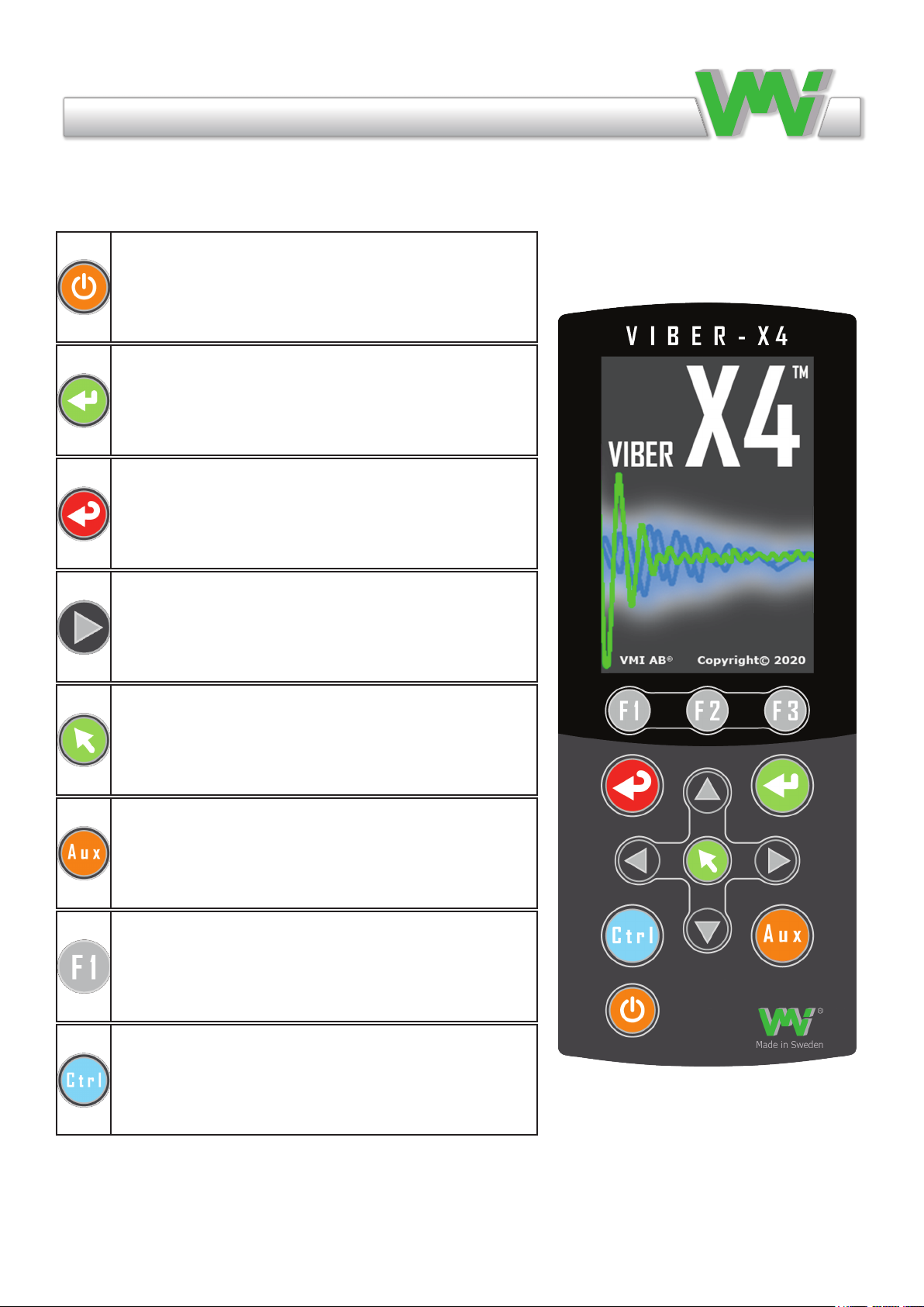
Instrument basics
This section contains basic information about how to operate the instrument and the meanings of the dier-
ent keys and symbols.
ON/OFF Used to switch the instrument ON and
OFF.
OK (Enter) Used to start a measurement, resume the
measurement from Hold status, conrm an action or
go forward in a menu.
ESC (Escape) Used to cancel an action or to return
to the previous menu.
Arrows (up, down, left, right). Used to change the
selected items or move the cursor depending on the
context.
Menu Used to access the menu shortcut window.
It is also used to save changes in edit controls or to
select an item depending on the context.
AUX Used to stop a measurement.
Function keys (F1, F2, F3) Used to select an action
in the shortcut bar displayed above the keys. These
are also used together with the Ctrl key to select ac-
tions shown in the second (blue) row of the shortcut
bar.
Ctrl Only used together with other keys (mainly
function keys) to generate alternative key codes.
5
Vibraon Measurement Instruments
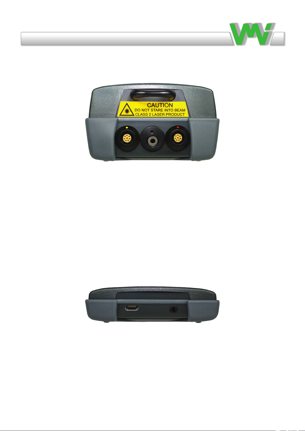
From the left in the picture:
Tacho connector (with yellow dot): Used to connect a tacho sensor to measure rotation speed
and to perform balancing.
Temperature sensor (below) and laser module: Used to measure the temperature of an object
by pointing the laser beam at the object.
Note that staring at the laser beam can damage your eyes.
Vib input (with red dot): Used to connect dierent types of sensors to measure vibration and
perform balancing.
From the left in the picture:
USB-C connector: Used to connect the VIBER X4™ to a PC to transfer les or to connect to
a battery charger.
Audio connector: Used to connect a headphones connector with a stereo 3.5mm plug.
Connectors and sensors on front and rear sides.
6
Vibraon Measurement Instruments
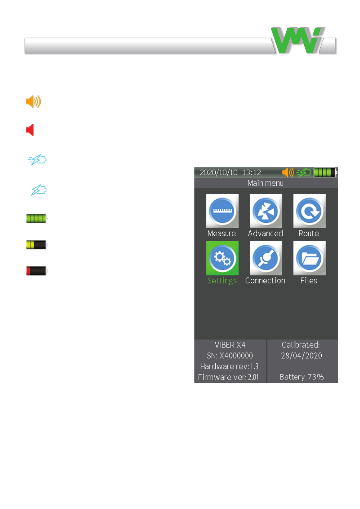
Main menu description
• Current date and time.
• Audio. Only shown when the audio function is
enabled.
• Mute. Shown when mute is enabled while using
audio.
• Quick charger. Shown when charging with the
original VMI quick charger.
• Charger. Shown when using common chargers
with a 5V output.
• Battery. Each segment in the picture corresponds
to 20% battery capacity.
• Battery. The segments turn yellow when only
40% battery capacity remains.
• Battery. The segment turns red when only 20%
battery capacity remains.
• Menu description.
• Menus icons. Various menus included in the main menu.
• Model number.
• Serial number.
• Hardware version number.
• Firmware version number.
• Calibration date.
• Percentage battery capacity remaining.
7

Vibraon Measurement Instruments
Instrument settings
• Tools. Check the instrument functions.
• General. Set the general instrument parameters.
• Transducers. Edit the used transducer.
• Select Sensor. Choose which transducer is to be used.
• Update. Update the instrument rmware and applications.
• Factory Reset. Restore default settings.
• Info. Information regarding the running applications and resources.
8

Vibraon Measurement Instruments
Tools
This menu contains various tools for checking the functionality of the keypad, the
display and Bias measurement.
Keypad
This tool performs a keypad test. Every time you press a key, the key name and
the corresponding key code will be shown. Press ESC to exit the test.
Display
This tool performs a color display test. You can check if the screen colors are as
expected and if any pixels are defective.
Press the F1, F2, F3, AUX and OK keys to change the ll color to red, green, blue,
white or black. Press ESC to exit the test.
Bias
This tool is used to check for transducer or cable faults.
When using the accelerometer, if the value is low and possibly close to zero, it
means that there is a short circuit in the transducer or cable. If the value is high
and close to the value of the power supply, it means that there is a break in the
transducer or cable.
When using displacement transducers, this tool can be used to adjust the proper
position, usually when the bias reaches half of the supply voltage.
9

Vibraon Measurement Instruments
General settings
Use the arrows and the OK key to change and save values.
• Set date
Set the date, which is also used whenever data is stored.
• Set clock
Set the clock, which is also used whenever data is stored.
• Unit system
Depending on this setting, the measuring units available in dif-
ferent menus will be restricted by the system selected.
For example: For vibration velocity measurements, the Metric
setting uses mm/s as the measuring units while the Imperial
System setting uses in/s.
• Language
The default language is English, but almost any language can
be installed. To set a new language, rst make sure you have
placed the new language le in the SYSTEM folder, then go to
the Update menu and Update language. You can then change the
language.
• Backlight o time (sec)
The time (seconds) from the last key being pressed by the user
until the LCD backlight turns o automatically to save power.
You can select from Never, 10, 30, 60, 120 and 300 seconds.
• Auto o time (min)
The time (minutes) from the last key being pressed by the user
until the instrument shuts down to save power. You can select
from Never, 1, 30, 60 and 120 minutes.
• Backlight level
This is used to set the backlight level in which the instrument
starts.
10

Vibraon Measurement Instruments
Transducers
In this menu, you can edit a list of sixteen transducers which can be used for the
measurements. The rst three positions are prepared for accelerometer, velocity
and displacement sensors.
• Name
Transducer description [max 15 characters]. This will appear whenever the pro-
gram displays transducer characteristics or asks for transducer selection.
• Transducer type
Transducer type. This can be Accelerometer, Velocimeter, Displacement or Pro-
cess AC.
• Sensitivity
Transducer sensitivity, in mV/Unit. Notice that the unit may be dierent de-
pending on the type of transducer. The value can be set from between 1 and
10000.
• Bias Low
The lowest bias voltage accepted. Used to determine if the transducer works
prop- erly if the Check bias option is selected. The set value can be between -24V
and 24V.
• Bias High
The highest bias voltage accepted. Used to determine if the transducer works
prop- erly if the Check bias option is selected. The set value can be from -24V to
24V.
• Power supply
The instrument will supply a current of 4 mA (at max 24V) to the transducer, if
this is enabled by the setting.
• Stabilization time (sec)
The minimum time to wait for a transducer to be stable after power is turned on.
This can be between 0.5 and 10 seconds.
• Check Bias
The instrument will measure and compare the bias voltage with the Bias Low and
Bias High values. If the measured bias is lower or higher than the set values, the
instrument will indicate a transducer error.
• Additional power 24V
This enables a separate 24V supply to the transducer.
• Function keys
F1 previous transducers, F2 next transducer, F3 default settings.
11
Vibraon Measurement Instruments
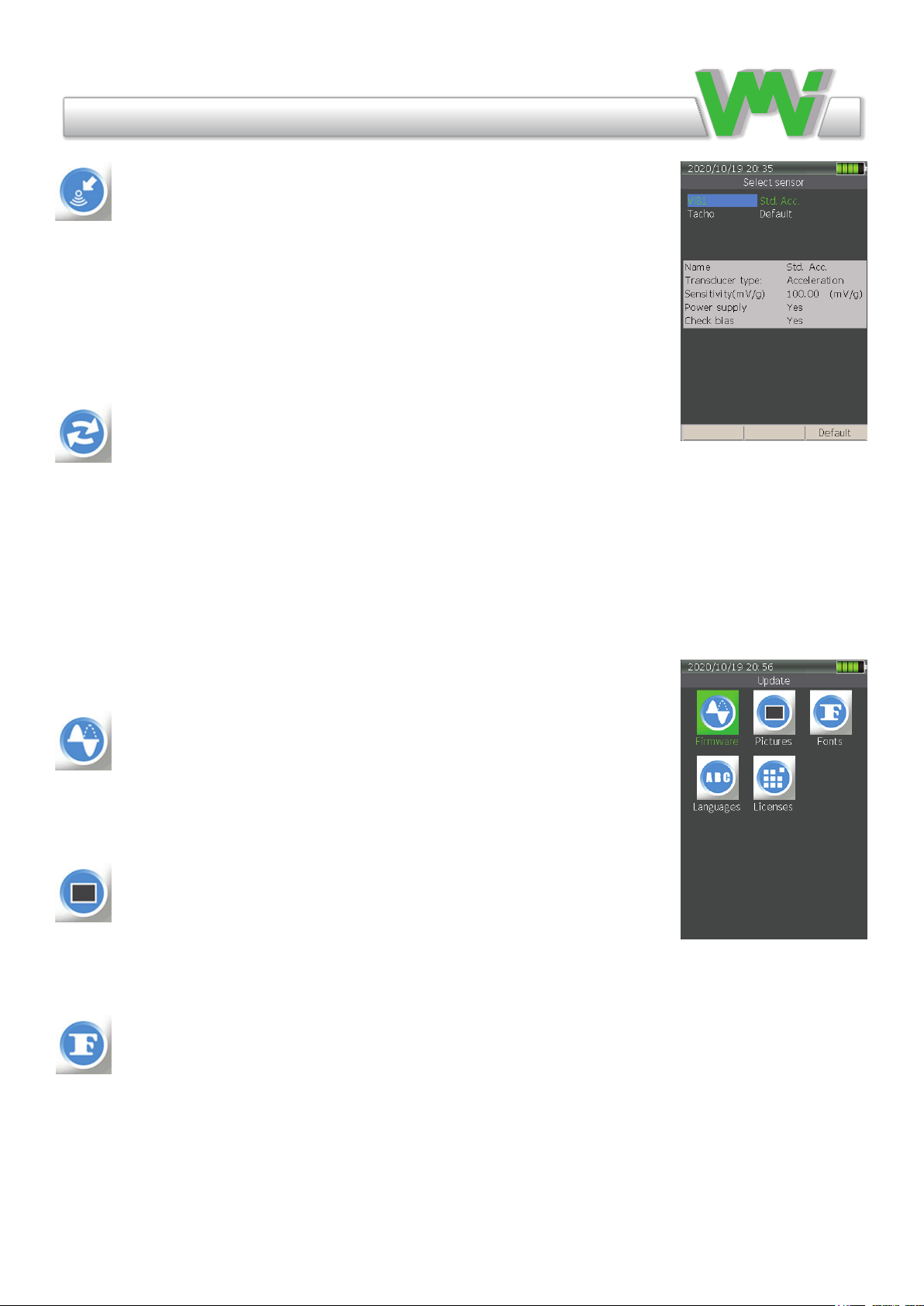
Select sensor
This menu contains conguration settings for Vib1 and tachometer inputs. The
settings will apply to all measurements. In most measurement settings, this menu is
accessible by the Function key F1.
Tacho Idle This setting is to congure when the tachometer will trigger each rota-
tion. When Low is selected, the leading edge of the reective tape will initiate the
count and when High is selected, the trailing edge will trigger the count.
Update
This feature allows you to update dierent applications to the latest versions. A list
of all current versions of applications can be found in the Info menu.
The latest update le must be placed in the SYSTEM folder on the instrument’s
memory card before updating.
NOTE 1 Connect the battery charger before starting an update to avoid any prob-
lems due to a sudden power failure (low battery level).
NOTE 2 The instrument MUST be restarted after updating in order to run the new
rmware or application.
Firmware
This updates the instrument’s main rmware. Choose the latest version in the list if
you have more than one le and press OK to start updating.
The le extension is: PRG Example: XV4_V201.PRG.
Pictures
This updates the instrument’s pictures and icons. Choose the latest version in the
list if you have more than one le and press OK to start updating.
The le extension is: BIN Example: X4P_V105.BIN.
Fonts
This updates the instrument’s fonts that are used for dierent languages. Choose the
latest version in the list if you have more than one le and press OK to start updat-
ing. The le extension is: BIN Example: X4F_V120.BIN.
12
Vibraon Measurement Instruments
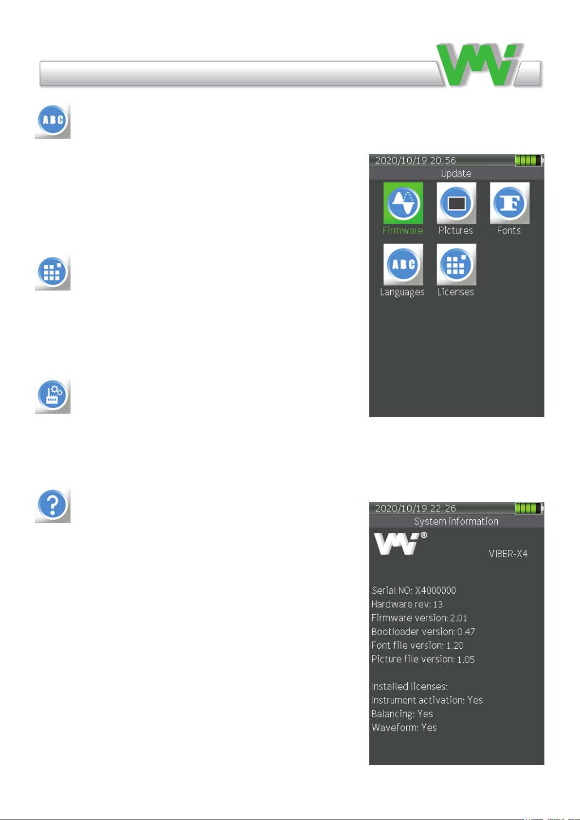
Language
This updates the instrument’s language. The instrument’s default
language is English but other languages can be easily installed using
this feature and changes in the general settings menu.
Select the desired language le from the list if you have more than
one le and press OK to start updating.
The le extension is: LNG. For example, the Swedish language le
is SWEX4003.LNG.
Licenses
This updates the instrument’s licenses. This le can be easily re-
ceived via e-mail and installed afterwards to access several new
functions. Choose the le and press OK to start updating. The le
name is always the same as the instrument’s serial number.
The le extension is: LIC. For example: X4000000.LIC
Factory reset
Restores default settings in all menus. Transducer sensitivities will
also be restored.
System information
All system information is shown here such as serial number, rm-
ware and hardware versions, bootloader, font and picture versions.
All installed licenses are also shown.
13
Vibraon Measurement Instruments
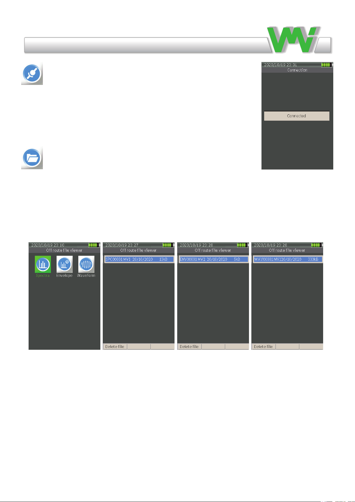
Connection
This maintains communication between the instrument and the PC via a USB port.
Connect the instrument to a PC with a USB-C cable, start the instrument and go to
the connection menu. “Connected” appears on the display when communication is
active.
Files
All data is stored in les. The instrument uses a predened set of folders, such
as BALANCE, ENVELOPE, ROUTE, SPECTRA, SYSTEM and WAVEFORM, to
store the les. This menu contains stored O Route measurements of spectra, en-
velope and waveform signals. This makes it possible to select a measurement and
view it later. It also makes it possible to export a le from one format to another
and save it in the same folder with the same name but with a dierent extension.
14
Vibraon Measurement Instruments
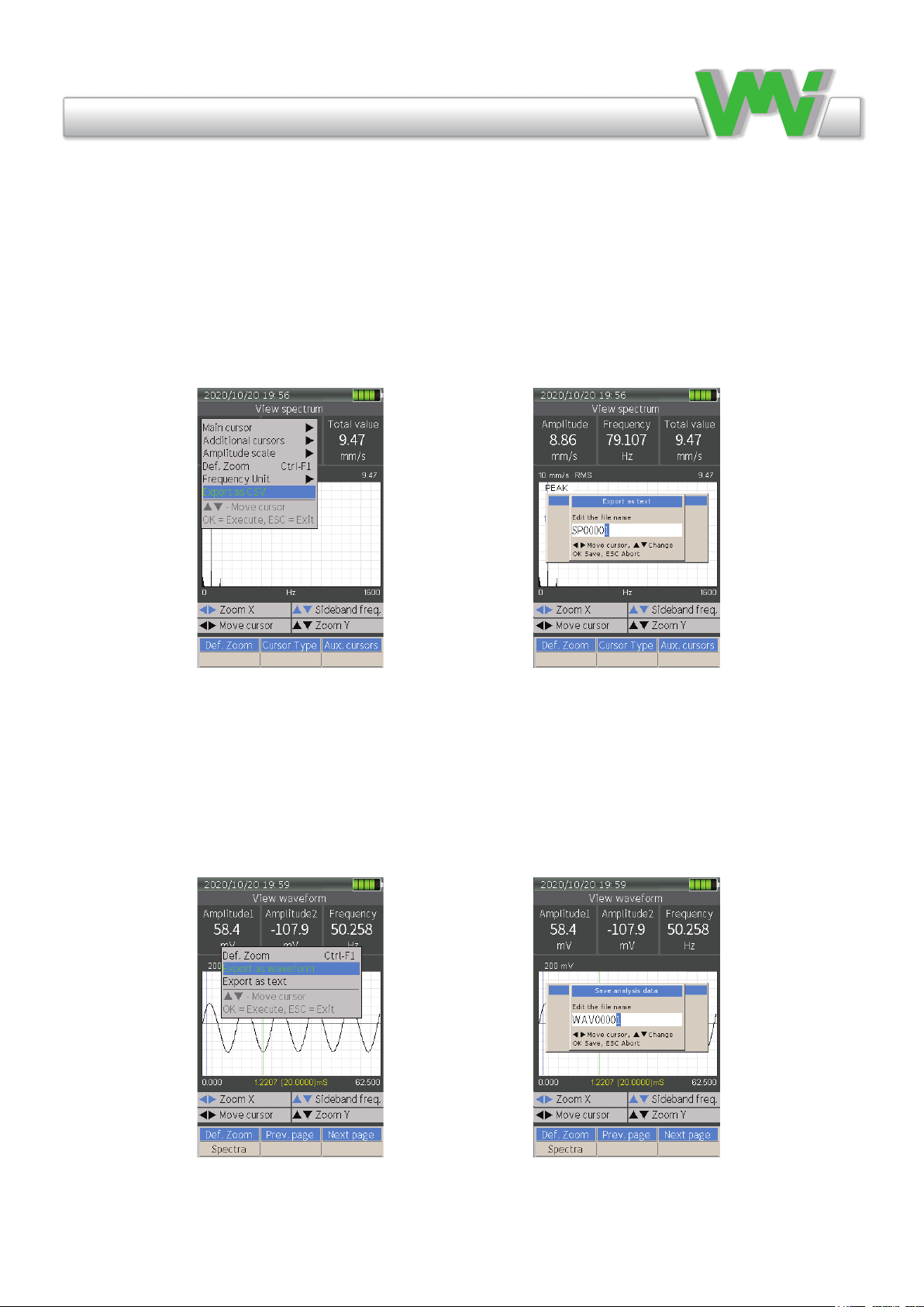
Exporting data in le menu
It is possible to export saved data in a dierent format. This allows you to use saved measurement results
from Viber X4 in a third-party software. Spectrum and envelope les can be exported from MV1 format to
CSV format and waveform les can be exported to WAV or TXT format.
Export from Spectrum or Envelope le
Go to le menu, open a saved spectrum or envelope le, press the MENU key, select Export as CSV, select a
le name and save it in the instrument’s memory card.
Export from Waveform le
Go to le menu, open a saved waveform le, press the MENU key, select Export as WAV or TXT, select a
le name and save it in the instrument’s memory card.
15

Vibraon Measurement Instruments
Route
Route measurement is used when machines are measured on a regular basis. The Route information is down-
loaded from the SpectraPro® PC software and the measurements, notes and other information are trans-
ferred back to the SpectraPro® software.
Route measurements and their settings are organized in the SpectraPro® software and downloaded to the
instrument. It is not possible to change the Route settings in the instrument. Route measurement is easy; it
measures the points on the dierent machines indicated on the VIBER X4™ display. The measurements are
automatically stored under the same name as the measuring point. When the measurements have been made,
you simply connect the instrument to the PC and all Route measurements are automatically transferred and
stored in the SpectraPro® database (see section on transferring Route).
The VIBER X4™ Instrument can measure various parameters using a predened list of measurements,
named Route. The Route should be created in the SpectraPro® software. Each type of measurement can be
congured in SpectraPro®. When the instrument measures the parameter, it will automatically congure the
measurement parameters.
The following measurements are supported by VIBER X4™ Route measurements.
• Vibration, such as total level, BC, Envelope and spectra.
• Temperature, with built-in IR transducer.
• Speed, with external sensor or manual input.
Transfer a Route to or from the Instrument
Before transferring a Route to the instrument, the Route should be created in the SpectraPro® software (for
more details, read the SpectraPro® User’s Manual).
Transferring a Route from the PC to VIBER X4™ can be done in two ways:
1. Directly from the SpectraPro® software to the VIBER X4™ using the Connection menu.
2. Indirectly in SpectraPro® by transferring the Route to a le and then copying the le to the Route folder
in the VIBER X4™ memory card. If you copy the Route le to another folder or to the memory card root
directory, the instrument will not show the le in the existing Route list.
A large number of Route les can be stored in the memory card; however, when the Route list menu is
shown in the Route manager, the instrument always checks the integrity of all Route les stored, depending
on how many there are and the size of the Routes. This process takes time so we recommend only storing the
Routes you require.
Enter the Route manager to select another Route or to see the details of a Route.
You can select a Route that is loaded in the instrument. Use the arrow keys and then press OK.
16
Vibraon Measurement Instruments
Measuring in Route
When entering the Route menu, you enter the location of the last point selected in the most recently used
Route le. This means that when you stop the measurements in a Route, you can shut down the VIBER
X4™ to save power or make additional O Route measurements. You can then resume the Route measure-
ment at any time from where you left o by simply selecting the Route application again.
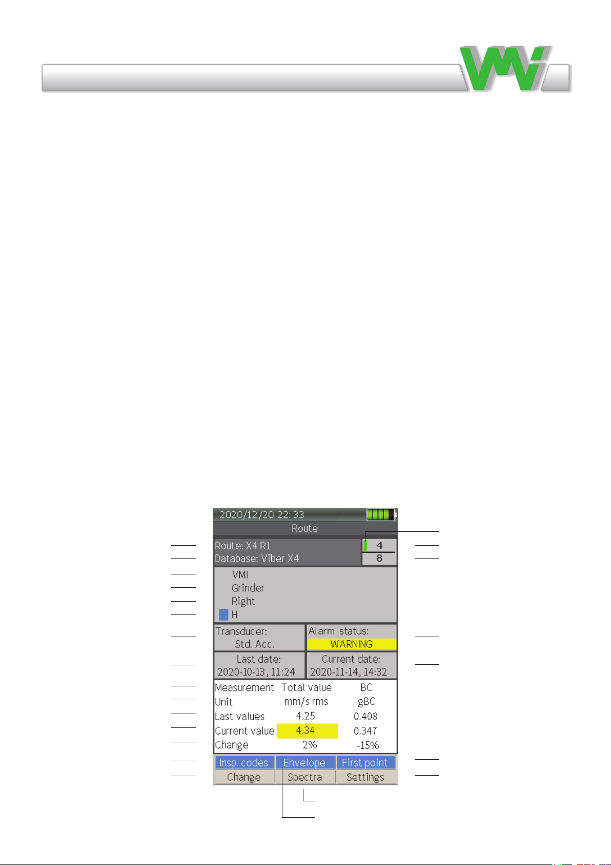
The Route screen displays the following items:
• The Route, database, department, machine, point and direction to be measured.
• Record status (Collected or not).
• Transducer type (selected in SpectraPro® software).
• Alarm status (Warning or Danger).
• Date and time of last collection.
• Date and time of current collection.
• Type of measurements made at the point.
• Last values of the point saved in the machine database.
• Current values of the point.
• Gradient of change as a percentage.
Route name
Database name
Department
Machine
Point
Direction
Transducer type
Date and time of last collection
Measurement type
Measurement unit
Last collection value
Current collection value
Gradient of change as a percentage
List of inspection codes Ctrl + F1
Route manager to change route le F1
Current record number
Total number of records in Route le
Date and time of current collection
Goes to rst record point Ctrl + F3
Route settings F3
Shows recorded current spectrum measurement F2
Green sign when record is collected
Shows recorded current envelope measurement Ctrl + F2
Alarm status. OK (black),
WARNING (yellow),
DANGER (red)
17

Vibraon Measurement Instruments
Instrument Route Manager
Enter the Route manager to select another Route or see the details of a Route.
You can select a Route loaded in the instrument. Use the arrow keys and press OK.
Using the function keys you can also:
• Details F1 Show Route details such as le name, database, Route name, le size and number of
records.
• Delete F2 Delete a route le.
• Copy F3 This function copies the contents of the Route le without measurement values and makes
it possible to collect measurements twice on the same occasion.
For example, collect measurements on a fan, perform a balance, then collect new measurement values
and save them in the copied le.
18

Vibraon Measurement Instruments
Getting started with Measurements
The general procedure for measurements using VIBER X4™ can be divided into 4 steps:
1. Parameter check: When pressing OK, the instrument will check if the transducers meet the required
conditions and start the data acquisition for the measurement. In the meantime, the instrument will display a
diagram related to the stability of the input signal and, for some measurements, auto ranging will ask you to
conrm the stability of the signal.
2. Data collection: The instrument acquires the necessary data. Depending on the settings, this can take up
to 30 seconds. It will also start to process and display the data. The measurement can be stopped either auto-
matically or manually using the Aux key, depending on reference, setting and/or measurement.
3. Settings: Press the F3 key during measurement to enter the settings menu where you can set the parame-
ters for the measurement. By pressing F3 the parameters will be set to default, which covers the majority of
situations. The instrument always saves the last used settings for each type of measurement.
4. Save: When the measurement is stopped by pressing the Aux key, the collected data can be saved in les
by selecting Save from the Menu key. You can review the les using the File Manager. For some measure-
ments, such as Waveform, if the measurement has not been saved, a question will appear about saving before
exiting the measurement.
19

Vibraon Measurement Instruments
General Measurement Settings
In this section, the general application settings that are most commonly used by dierent applications
are described. The settings can vary from application to application but their function is the same.
Measurement type
Millivolt, Acceleration, Velocity or Displacement.
Depending on the choice, the instrument will integrate and display the units of measurement dierently.
Detection type
RMS , Peak or Peak-Peak.
RMS The RMS value of a set of values, or of a continuous-time waveform, is the square root of the arithme-
tic mean (average) of the squares of the original values or the square of the function that denes the continu-
ous waveform.
Peak The amplitude of a sine wave at the frequency of interest which is calculated from the RMS value. It
can be used for detection of acceleration, velocity and high frequency energy.
Peak-Peak The amplitude of a sine wave at the frequency of interest which is calculated from the RMS val-
ue. This is used for detection of displacement and sometimes used for high frequency energy. In the case of
the sine wave, the Peak-Peak value is exactly twice the Peak value because the waveform is symmetrical.
HP Filter
High pass lter frequency for the input signal. This sets the lowest level from which the frequency will be
displayed and calculated. If disabled, the frequency starts from zero (0). The setting depends on the type of
measurement.
LP Filter
Low pass lter frequency for the input signal. This sets the highest level from which the frequency will be
displayed and calculated. This setting depends on the type of measurement.
Max. frequency
800, 1000, 1600, 3200, 6400 or 12800 Hz (depending on the type of measurement).
These are the adjustable frequencies. The unit Hz is 1 period/second, equivalent to 60 cycles per minute.
The resolution depends on the frequency range and the number of lines selected.
Number of lines (800, 1600, 3200, 6400 or 12800)
In this setting the number of lines is set and displayed in spectra. The resolution increases when the number
of lines increases, as does the time needed for data acquisition.
From this it can be seen that a high resolution spectrum requires a long time to collect the data. This has
nothing to do with the speed of the calculations in the instrument, it is simply a natural law of frequency
analysis.
During measurement, the dynamic parameters of the machine (one example is speed) should not change. For
this reason it can be better to choose a low number of lines in situations where the parameters of the machine
are not steady or if you would like to study “real time” transients.
20
Table of contents
Other VMI Measuring Instrument manuals


Popular Measuring Instrument manuals by other brands


CAI
CAI 700 CLD Series Operator's manual

Rion
Rion NL-42 Technical notes

Vanguard Instruments
Vanguard Instruments CT-7000 S3 user manual

Major tech
Major tech TrueRMS MT765 instruction manual

Tonghui Electronics
Tonghui Electronics TH1778A Operation manual

Endress+Hauser
Endress+Hauser analytikjena multi EA 5100 Service manual


