VMIC VMIVME-7454 User manual

12090 South Memorial Parkway
Huntsville, Alabama 35803-3308, USA
(205) 880-0444 6(800) 322-3616 6Fax: (205) 882-0859
VMIVME-7454
VMEbus Floppy/Hard Disk Module
Installation Manual
522-007454-000 Rev. D

© Copyright 1997. The information in this document has been carefully checked and is believed to be entirely reliable. While all
reasonable efforts to ensure accuracy have been taken in the preparation of this manual, VMIC assumes no responsibility resulting from
omissions or errors in this manual, or from the use of information contained herein.
VMIC reserves the right to make any changes, without notice, to this or any of VMIC’s products to improve reliability, performance,
function, or design.
VMIC does not assume any liability arising out of the application or use of any product or circuit described herein; nor does VMIC convey
any license under its patent rights or the rights of others.
For warranty and repair policies, refer to VMIC’s Standard Conditions of Sale.
AMXbus, BITMODULE, COSMODULE, DMAbus, IOWorks, IOWorks Access, IOWorks Foundation, IOWorks man
figure™, IOWorks Manager™, IOWorks Server™, MAGICWARE, MEGAMODULE, PLC ACCELERATOR (ACCELERATION),
Quick Link, RTnet, Soft Logic Link, SRTbus, TESTCAL, “The Next Generation PLC”, The PLC Connection,
TURBOMODULE, UCLIO, UIOD, UPLC, Visual Soft Logic Control(ler)™, VMEaccess, VMEmanager, VMEmonitor,
VMEnet, VMEnet II, and VMEprobe are trademarks of VMIC.
COPYRIGHT AND TRADEMARKS
VMIC
All Rights Reserved
This document shall not be duplicated, nor its contents
used for any purpose, unless granted express written
permission from VMIC.
The I/O man figure, UIOC®,Visual IOWorks®, and WinUIOC® are registered trademarks of VMIC.
Microsoft, Microsoft Access, MS-DOS, Visual Basic, Visual C++, Win32, Windows, and XENIX are registered trademarks and Windows NT
is a trademark of Microsoft Corporation.
MMX is a trademark and Pentium is a registered trademark of Intel Corporation.
Other registered trademarks are the property of their respective owners
®
UIOC
WinUIOC
(I/O man figure) (IOWorks man figure)

1
INSTALLATION OF THE VMIVME-7454
VMEbus FLOPPY/HARD DISK MODULE
The VMIVME-7454, VMEbus Floppy/Hard Disk Module is designed to be used in
conjunction with the VMIC suite of Pentium® processor-based VMEbus CPU
products, including the VMIVME-7587, VMIVME-7588, and the VMIVME-7686.
These CPU products include a SCSI 2 I/O port for hard drive cable connection.
This installation guide describes the direct cable connection of the module with the
VMIVME-7588 and VMIVME-7688, and the cable-to-adaptor connection with the
VMIVME-7587.
The VMIVME-7454 is available with four different cable configurations: wide, narrow,
single, or multi-drop. A wide cable configuration supports a 68-pin SCSI connector.
The narrow cable is used with the 50-pin SCSI connector. The single drop cable
configuration connects two devices, but includes a piggybacked connector which
allows another cable to daisy chain or plug into the back. The multi-drop cable
attaches to up to five devices.
Contents
Two separate procedures are outlined in this installation manual, these include:
1. Connecting the VMIVME-7454 to a VMIVME-7588 or VMIVME-7686.
2. Connecting the VMIVME-7454 to a VMIVME-7587.
Do not power-up the VMIVME-7454 without it being connected to the CPU Board in
one of the hardware configurations shown on the following pages.
Powering up an unconnected module causes the loss of any software configuration on
the VMIVME-7454 hard disk.
WARNING

2
VMIVME-7454 Installation Guide
Procedure 1.0 Connect the VMIVME-7454 to a VMIVME-7588 or VMIVME-7686
When removing the CPU board and the VMIVME-7454, first eject the VMIVME-7454,
then eject the CPU board and slide both boards out simultaneously.
1. Slide the VMIVME-7454 board into the VMEbus chassis card guide.
2. Select the proper SCSI ID for the hard disk (see Table 1 and Figure 1).
Determine the correct setting from the table and adjust the setting on the
VMIVME-7454.
3. Place the CPU board, component side up, on a flat surface.
4. Connect the Floppy Drive Cable (360-000106-003) by connecting the 34-pin
female connector to the 34-pin male connector on the component side of the
CPU board. Reference Figure 2 on page 5 for the location of the male pin
connector.
5. To connect the Hard Drive Single Drop cable (360-010045-007), connect the single
68-pin male connector of the cable to the 68-pin female SCSI 2 connector on the
front panel of the CPU board. Do not connect the Stacked Double Connector End of
the Single Drop cable to the CPU board front panel as this will prohibit further daisy
chaining (see Figure 1).
To connect the Hard Drive Multi-drop cable (360-010042-000), connect the first
68-pin male SCSI 2 connector cable into the 68-pin female SCSI connector on the
front panel of the CPU board (see Figure 1).
When using the Multi-drop cable, ensure that the hard drive is the last device
connected. Use the last connector on the cable; otherwise, use the connector best
suited for your application.
6. Slide the CPU board into the VMEbus chassis.
7. Attach cables to the VMIVME-7454 front panel as shown in Figure 1.
Note
Note

3
Figure 1 Connecting the VMIVME-7454 to a VMIVME7588, Including the SCSI 2 Selection Switch
4
VMIVME-7454 Installation Guide
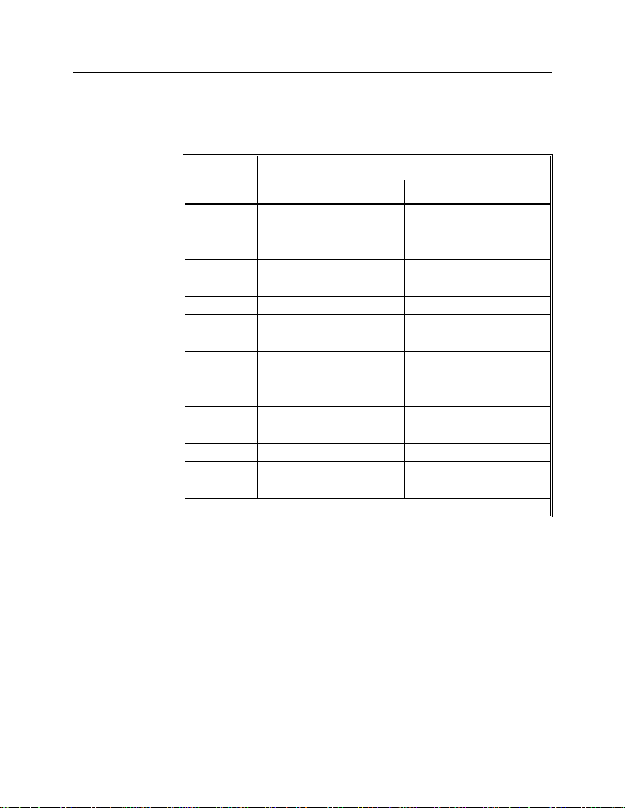
Table 1 SCSI 2 ID Settings
Switch Positions
SCSIID1234
0 Off Off Off Off
1 On Off Off Off
2 Off On Off Off
3OnOnOffOff
4 Off Off On Off
5 On Off On Off
6 Off On On Off
7 *On On On Off
8 Off Off Off On
9OnOffOffOn
10 Off On Off On
11 On On Off On
12 Off Off On On
13 On Off On On
14OffOnOnOn
15 On On On On
*Conflicts with the CPU SCSI Controller ID of 7.

5
Figure 2 Connecting a Floppy Cable to a VMIVME-7588 or VMIVME-7686
Floppy Connector Cable
VMEbus CPU
Component Side
IDE Hard Drive
Floppy Drive
Connector
Board
360-000106-003
from the VMIVME-7454
Connector
(Not Used)
6
VMIVME-7454 Installation Guide
Procedure 2.0 Connect the VMIVME-7454 to a VMIVME-7587
When removing the CPU board and the VMIVME-7454, first eject the VMIVME-7454,
then eject the CPU board and slide both boards out simultaneously.
1. Slide the VMIVME-7454 board into the VMEbus chassis card guide.
2. Select the proper SCSI ID for the hard disk. Reference Table 1 on page 4 and the
SCSI ID setting locations illustrated on Figure 3. Determine the correct setting
from the table and adjust the setting on the VMIVME-7454.
3. Place the CPU board, component side up, on a flat surface.
4. Connect the Floppy Drive Cable (360-000106-003) by connecting the 34-pin
female connector to the 34-pin male connector on the component side of the
CPU board. Reference Figure 2 on page 5 for the location of the male pin
connector.
5. To connect the Hard Drive Single Drop cable (360-010054-007), connect the single
68-pin male connector of the SCSI 2 connector cable into the SCSI 2 Converter
(323-250049-000), then plug the converter into front panel of the CPU board. Do
not connect the Stacked Double Connector End of the Single Drop cable to the SCSI 2
Converter as this will prohibit further daisy chaining (reference Figure 3).
To connect the Hard Drive Multi-drop cable (360-010049-020), connect the first
68-pin male connector cable into the SCSI 2 Converter (323-250049-000), then
plug the converter into front panel of the CPU board (reference Figure 3).
When using the Multi-drop cable, ensure that the hard drive is the last device
connected. Use the last connector on the cable; otherwise, use the connector best
suited for your application.
6. Slide the CPU board into the VMEbus chassis.
7. Attach cables to the VMIVME-7454 front panel as shown in Figure 3.
Note
Note

7
Figure 3 Connecting a VMIVME-7587 to a VMIVME-7454

8
VMIVME-7454 Installation Guide
Table of contents
Other VMIC Control Unit manuals


