ETAS ES4455.2 User manual

ES4455.2 Load Carrier Board
ES4450.3 Load Carrier Board for 4 RB CRS Injectors
ES4451.4 Load Carrier Board for 4 RB GDI Injectors
ES4452.1 Load Carrier Board for 4 RB GDI Injectors, CVO
ES4453.1 Load Carrier Board for 4 RB HDEV6 GDI Injectors, CVO
ES4457.1 Load Carrier Board for 4 RB CRS Injectors, VCC and VCA
ES4458.1 Load Carrier Board for 4 RB PFI Injectors, CVO
User’s Guide

2
Copyright
The data in this document may not be altered or amended without special noti-
fication from ETAS GmbH. ETAS GmbH undertakes no further obligation in rela-
tion to this document. The software described in it can only be used if the
customer is in possession of a general license agreement or single license. Using
and copying is only allowed in concurrence with the specifications stipulated in
the contract.
Under no circumstances may any part of this document be copied, reproduced,
transmitted, stored in a retrieval system or translated into another language
without the express written permission of ETAS GmbH.
© Copyright 2019 ETAS GmbH, Stuttgart
The names and designations used in this document are trademarks or brands
belonging to the respective owners.
V1.0.0 R05 EN - 09.2019

ES4455.2 Load Carrier Board - User’s Guide 3
Contents
ETAS Contents
1 Introduction . . . . . . . . . . . . . . . . . . . . . . . . . . . . . . . . . . . . . . . . . . . . . . . . . . . . . . 5
1.1 Properties . . . . . . . . . . . . . . . . . . . . . . . . . . . . . . . . . . . . . . . . . . . . . . . . . . . 5
1.1.1 Properties of the ES4455.2 Load Carrier Board and its Variants
ES4450.3, ES4451.4, ES4452.1, ES4453.1, ES4457.1 and ES4458.1
Mounted with Load Modules. . . . . . . . . . . . . . . . . . . . . . . . . . . . . . 6
1.1.2 Block Diagram . . . . . . . . . . . . . . . . . . . . . . . . . . . . . . . . . . . . . . . . . 8
1.2 Basic Safety Notices . . . . . . . . . . . . . . . . . . . . . . . . . . . . . . . . . . . . . . . . . . . 9
1.2.1 Identification of Safety Notices . . . . . . . . . . . . . . . . . . . . . . . . . . . . 9
1.2.2 General Safety Information . . . . . . . . . . . . . . . . . . . . . . . . . . . . . . . 9
1.2.3 Requirements for Users and Duties for Operators. . . . . . . . . . . . . . . 9
1.2.4 Intended Use . . . . . . . . . . . . . . . . . . . . . . . . . . . . . . . . . . . . . . . . . 10
1.3 Identifications on the Product . . . . . . . . . . . . . . . . . . . . . . . . . . . . . . . . . . . 15
1.3.1 CE Mark . . . . . . . . . . . . . . . . . . . . . . . . . . . . . . . . . . . . . . . . . . . . 15
1.3.2 KC Mark . . . . . . . . . . . . . . . . . . . . . . . . . . . . . . . . . . . . . . . . . . . . 15
1.3.3 RoHS Conformity. . . . . . . . . . . . . . . . . . . . . . . . . . . . . . . . . . . . . . 16
1.3.4 Identification in Accordance with ISO 7010:2011 . . . . . . . . . . . . . 16
1.4 Product Return and Recycling . . . . . . . . . . . . . . . . . . . . . . . . . . . . . . . . . . 16
1.5 Materials Subject to Declaration . . . . . . . . . . . . . . . . . . . . . . . . . . . . . . . . . 17
1.6 About this Manual . . . . . . . . . . . . . . . . . . . . . . . . . . . . . . . . . . . . . . . . . . . 18
1.6.1 Working with this Manual . . . . . . . . . . . . . . . . . . . . . . . . . . . . . . . 18
2 Properties and Functions . . . . . . . . . . . . . . . . . . . . . . . . . . . . . . . . . . . . . . . . . . . . 21
2.1 Design of an Injector Simulation Environment . . . . . . . . . . . . . . . . . . . . . . . 21
2.2 Figures of ES4455.2 and its Mounted Variants ES4450.3, ES4451.4, ES4452.1,
ES4453.1, ES4457.1 and ES4458.1 . . . . . . . . . . . . . . . . . . . . . . . . . . . . . . . 24
2.2.1 ES4455.2 Load Carrier Board. . . . . . . . . . . . . . . . . . . . . . . . . . . . . 24
2.2.2 ES4450.3 Load Carrier Board for 4 RB CRS Injectors . . . . . . . . . . . 25
2.2.3 ES4451.4 Load Carrier Board for 4 RB GDI Injectors. . . . . . . . . . . . 25
2.2.4 ES4452.1 Load Carrier Board for 4 RB GDI Injectors, CVO . . . . . . . 26

ES4455.2 Load Carrier Board - User’s Guide4
Contents ETAS
2.2.5 ES4453.1 Load Carrier Board for 4 RB HDEV6 GDI Injectors, CVO . 26
2.2.6 ES4457.1 Load Carrier Board for 4 RB CRS Injectors, VCC and VCA 26
2.2.7 ES4458.1 Load Carrier Board for 4 RB PFI Injectors, CVO . . . . . . . . 27
2.3 Procedure for Installation and Removal . . . . . . . . . . . . . . . . . . . . . . . . . . . . 28
2.3.1 Installation in the ES4408.1 Load Chassis. . . . . . . . . . . . . . . . . . . . 29
2.3.2 Installation in the ES5372.1 Carrier for ES4455 Load Boards . . . . . 29
2.3.3 Installation in the ES5300.1-A Housing and the ES5300.1-B Housing
via ES5372.1 . . . . . . . . . . . . . . . . . . . . . . . . . . . . . . . . . . . . . . . . . 29
2.3.4 Connecting Cable . . . . . . . . . . . . . . . . . . . . . . . . . . . . . . . . . . . . . 30
2.4 Fuses . . . . . . . . . . . . . . . . . . . . . . . . . . . . . . . . . . . . . . . . . . . . . . . . . . . . . 31
2.4.1 Fuses on the ES4455.2 Load Carrier Board. . . . . . . . . . . . . . . . . . . 31
2.4.2 Replacing Fuses on the ES4455.2 Load Carrier Board. . . . . . . . . . . 31
2.5 Interface for Load Modules on the ES4455.2 Load Carrier Board . . . . . . . . . 34
2.6 Piezo Signal Generator . . . . . . . . . . . . . . . . . . . . . . . . . . . . . . . . . . . . . . . . 34
2.7 Equivalent Circuit . . . . . . . . . . . . . . . . . . . . . . . . . . . . . . . . . . . . . . . . . . . . 35
3 Connections and Connectors . . . . . . . . . . . . . . . . . . . . . . . . . . . . . . . . . . . . . . . . 37
3.1 Backplane Connector CO200 of the ES4455.2 Load Carrier Board . . . . . . . 37
3.2 Plug Connector CO1200 on ES4455.2, CO150 and CO100 on the Load Mod-
ules . . . . . . . . . . . . . . . . . . . . . . . . . . . . . . . . . . . . . . . . . . . . . . . . . . . . . . 38
3.3 Connections and Plug Connections for Installation in the ES4408.1 Load Chassis
38
3.3.1 Plug Connectors "Load 7", " Load 8-1" and "Load 8-2". . . . . . . . 38
3.3.2 Plug Connector "Meas 7", "Meas 8-1" and "Meas 8-2" on ES4408.1
Load Chassis . . . . . . . . . . . . . . . . . . . . . . . . . . . . . . . . . . . . . . . . . 41
3.4 Connections and Plug Connections for Installation in the ES5300.1-A Housing
or in the ES5300.1-B Housing . . . . . . . . . . . . . . . . . . . . . . . . . . . . . . . . . . . 43
3.4.1 "X2 Load" Plug Connector . . . . . . . . . . . . . . . . . . . . . . . . . . . . . . 45
3.4.2 "X1 Measure" Plug Connector . . . . . . . . . . . . . . . . . . . . . . . . . . . 46
4 Technical Data and Standards . . . . . . . . . . . . . . . . . . . . . . . . . . . . . . . . . . . . . . . . 47
4.1 Technical Data . . . . . . . . . . . . . . . . . . . . . . . . . . . . . . . . . . . . . . . . . . . . . . 47
4.2 Meets Norms and Standards . . . . . . . . . . . . . . . . . . . . . . . . . . . . . . . . . . . . 48
5 Ordering Data and Scope of Delivery. . . . . . . . . . . . . . . . . . . . . . . . . . . . . . . . . . . 49
6 ETAS Contact Addresses . . . . . . . . . . . . . . . . . . . . . . . . . . . . . . . . . . . . . . . . . . . . 51
Index . . . . . . . . . . . . . . . . . . . . . . . . . . . . . . . . . . . . . . . . . . . . . . . . . . . . . . . . . . 53

ES4455.2 Load Carrier Board - User’s Guide 5
ETAS Introduction
1 Introduction
This User's Guide contains the description of the ES4455.2 Load Carrier Board
and its variants ES4450.3, ES4451.4, ES4452.1, ES4453.1, ES4457.1 and
ES4458.1 mounted with load modules.
This chapter contains information about the following topics:
• "Properties" on page 5
• "Basic Safety Notices" on page 9
• "Identifications on the Product" on page 15
– "CE Mark" on page 15
– "RoHS Conformity" on page 16
– "KC Mark" on page 15
• "Product Return and Recycling" on page 16
• "Materials Subject to Declaration" on page 17
• "About this Manual" on page 18
1.1 Properties
The ES4455.2 Load Carrier Board is a carrier board for load simulations, e.g.
injector loads, in a LABCAR HiL system.
To simulate injector loads, the following variants mounted with load modules
based on the ES4455.2 Load Carrier Board are available:
• ES4450.3 Load Carrier Board for 4 RB CRS Injectors
• ES4451.4 Load Carrier Board for 4 RB GDI Injectors
• ES4452.1 Load Carrier Board for 4 RB GDI Injectors, CVO
• ES4453.1 Load Carrier Board for 4 RB HDEV6 GDI Injectors, CVO
• ES4457.1 Load Carrier Board for 4 RB CRS Injectors, VCC and VCA
• ES4458.1 Load Carrier Board for 4 RB PFI Injectors, CVO
ES4450.3 and ES4451.4 are the successors to ES4450.2 and ES4451.3. The
ES4450.3 and ES4451.4 have the same functions as their respective predecessor
models.
The ES4452.1 Load Carrier Board for 4 RB GDI Injectors, CVO, ES4453.1 Load
Carrier Board for 4 RB HDEV6 GDI Injectors, CVO, the ES4457.1 Load Carrier
Board for 4 RB CRS Injectors, VCC and VCA and the ES4458.1 Load Carrier Board
for 4 RB PFI Injectors, CVO have an expanded scope of functions. They enable an
additional more precise simulation and modulation of the injection time through
integrated functions for the control algorithms of the ECU. These control algo-
rithms are CVO (Controlled Valve Operation) control for gasoline direct injection
in the case of ES4452.1, ES4453.1 and ES4458.1 or VCC (Valve Close Control)
control and VCA (Valve Close Adjustment) control for diesel direct injection in the
case of ES4457.1.
The expanded functions can be deactivated by the user in LABCAR OPERATOR.
After deactivating the function for CVO, the ES4452.1 can be operated analo-
gous to ES4451.4 and ES4451.3. Also, the ES4457.1 can be used in the same
way as ES4450.3 and ES4450.2 after deactivating the function for VCC and
VCA.

ES4455.2 Load Carrier Board - User’s Guide6
Introduction ETAS
The ES4408.1 Load Chassis features three slots of width 14 HP to accept the
ES4455.2 Load Carrier Board and the variants listed above. Fully mounted, it
enables the simulation of 12 injection loads.
In the same way, it is possible to install the ES4455.2 Load Carrier Board and its
mounted variants in the ES5300.1-A Housing and the ES5300.1-B Housing by
means of the ES5372.1 Carrier for ES4455 Load Boards.
In the ES5300.1-A Housing and the ES5300.1-B Housing, it is possible to install
5 boards of width 14 HP. Fully mounted, it enables the simulation of 20 injection
loads per housing.
1.1.1 Properties of the ES4455.2 Load Carrier Board and its Variants ES4450.3,
ES4451.4, ES4452.1, ES4453.1, ES4457.1 and ES4458.1 Mounted with Load
Modules
• 3 U/14 HP add-on card for a LABCAR HiL system.
• Compatibility with the ES4408.1 Load Chassis and, with the use of
adapter card ES5372.1 Carrier for ES4455 Load Boards, also with the
ES5300.1-A Housing and the ES5300.1-B Housing
• Four load inputs for connecting four simulated injection loads to an ECU
• Current measurement for four loads via four galvanically isolated
channels
• Voltage measurement for four loads via four galvanically isolated
channels
• Analog output Online_Probe for current or voltage measurement at one
selectable load
• On-board analysis of load current and load voltage
• Four digital outputs I_Dig_Out_1...I_Dig_Out_4 for outputting the injec-
tion time for each load. Based on the load response, the opening and
closing time of the respective load is also being output
• The signals I_Dig_Out_1, ... I_Dig_Out_4 can be connected to a LABCAR
HiL system.
The variants have the following additional properties:
ES4455.2 Load Carrier Board
• Slot for 4 loads
ES4450.3 Load Carrier Board for 4 RB CRS Injectors
• Simulation for four injectors of the Bosch Common Rail System.
ES4451.4 Load Carrier Board for 4 RB GDI Injectors
• Simulation for injectors of the Bosch HDEV5 gasoline direct injection
ES4452.1 Load Carrier Board for 4 RB GDI Injectors, CVO
• Simulation for injectors of the Bosch HDEV5 gasoline direct injection
• Additional supported functions of the motor ECU:
CVO (Controlled Valve Operation) control

ES4455.2 Load Carrier Board - User’s Guide 7
ETAS Introduction
ES4453.1 Load Carrier Board for 4 RB HDEV6 GDI Injectors, CVO
• Simulation for injectors of the Bosch HDEV6 gasoline direct injection
• Additional supported functions of the motor ECU:
CVO (Controlled Valve Operation)
ES4457.1 Load Carrier Board for 4 RB CRS Injectors, VCC and VCA
• Simulation for injectors of the Bosch Common Rail System CRI2-x
• Additional supported functions of the motor ECU:
VCC (Valve Close Control) and VCA (Valve Close Adjustment)
ES4458.1 Load Carrier Board for 4 RB PFI Injectors, CVO
• Simulation for Bosch PFI EV14 injectors
• Additional supported functions of the motor ECU:
CVO (Controlled Valve Operation)

ES4455.2 Load Carrier Board - User’s Guide8
Introduction ETAS
1.1.2 Block Diagram
Fig. 1-1 shows a block diagram of the ES4455.2 Load Carrier Board with four
loads in the ES4408.1 Load Chassis.
Fig. 1-1 Block diagram of the ES4455.2 Load Carrier Board with loads,
installed in the ES4408.1 Load Chassis.
Fig. 1-2 shows a block diagram of the ES4455.2 Load Carrier Board with four
loads in the ES5300.1-A Housing or ES5300.1-B Housing.
Fig. 1-2 Block diagram of the ES4455.2 Load Carrier Board with loads,
installed in the ES5300.1-A Housing or the ES5300.1-B Housing.
Back-
plane
SPI, I²C, JTAG ES4455.2_E
Control
Interface
Control
Interface
Ribbon
cable
ES4408.1
Load
Chassis
Control, Feedback
I
U
Load 1
I
U
Load 2
I
U
Load 3
I
U
Load 4
Speaker
Control
DAC
ADC ADC ADC ADC ADC ADC ADC ADC
Multiplexer 8:1
Register; Logic FPGA
I_Dig_Out_1
...4
Online_Probe
Piggyback Load
Load 7, Load 8-1, Load 8-2 Meas 7, - 8-1, - 8-2
VG48 CO200

ES4455.2 Load Carrier Board - User’s Guide 9
ETAS Introduction
1.2 Basic Safety Notices
Please observe the following safety notices to avoid health issues or damage to
the device.
1.2.1 Identification of Safety Notices
The safety notices contained in this manual are identified with the danger symbol
shown below:
The safety notices shown below are used for this purpose. They provide notes to
extremely important information. Please read this information carefully.
1.2.2 General Safety Information
Observe the following safety notices to avoid health issues or damage to the
device.
ETAS GmbH does not assume any liability for damages resulting from improper
handling, unintended use or non-observance of the safety precautions.
1.2.3 Requirements for Users and Duties for Operators
The product may be assembled, operated and maintained only if you have the
necessary qualification and experience for this product. Improper use or use by a
user without sufficient qualification can lead to damages or injuries to one's
health or damages to property.
The system integrator is responsible for the safety of systems that use the prod-
uct.
CAUTION!
identifies a hazard with low risk that could result in minor or medium
physical injuries or property damages if not avoided.
WARNING!
indicates a possible danger with moderate risk of death or (serious)
injury, if not avoided.
DANGER!
indicates an immediate danger with a high risk of death or serious
injury, if not avoided.
Note
All product related documentation (product Safety Advice and this User’s
Guide) must be read prior to the startup of the product!

ES4455.2 Load Carrier Board - User’s Guide10
Introduction ETAS
General Safety at Work
Follow the existing regulations for work safety and accident prevention. All appli-
cable regulations and laws regarding operation must be strictly adhered to when
using this product.
1.2.4 Intended Use
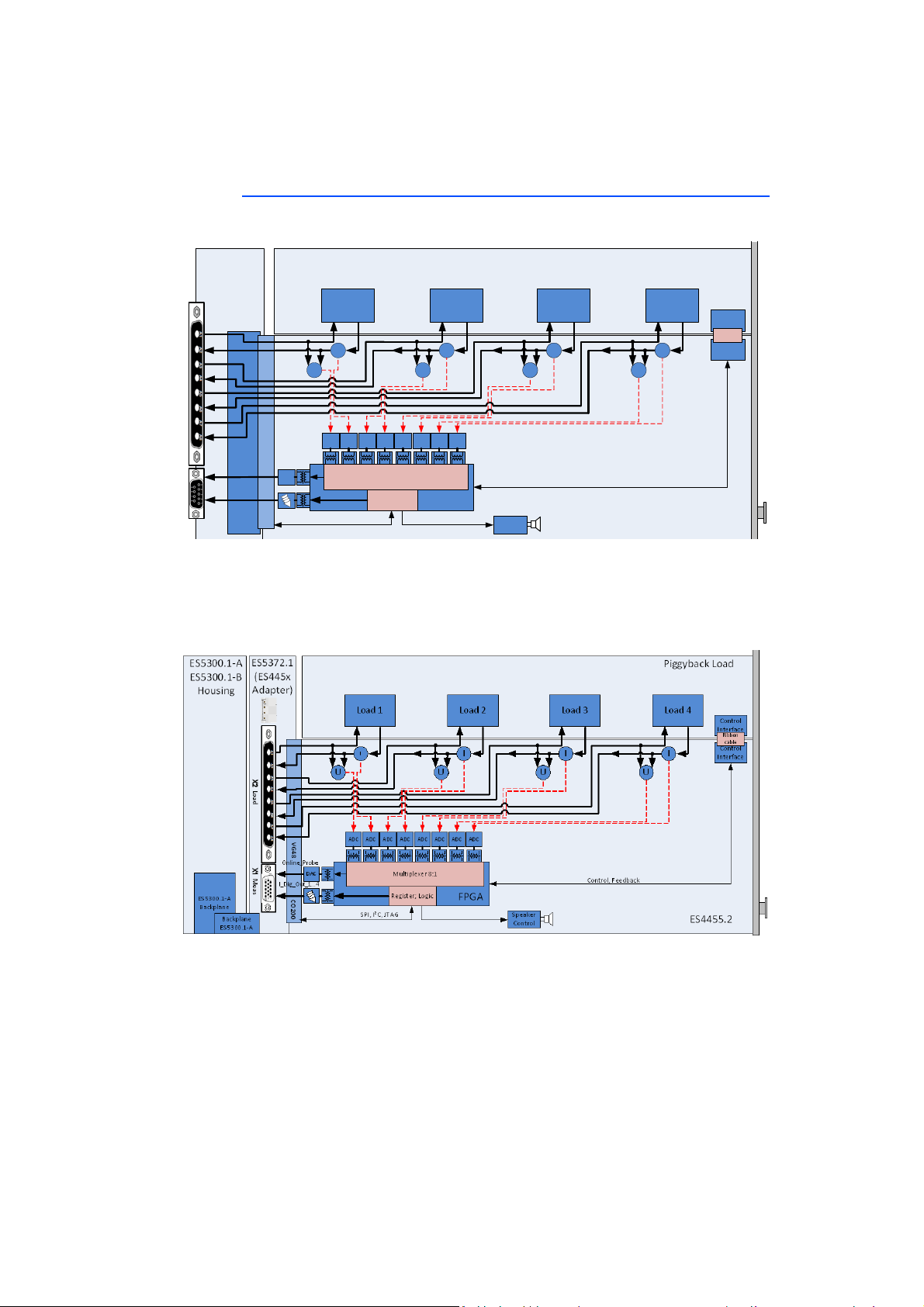
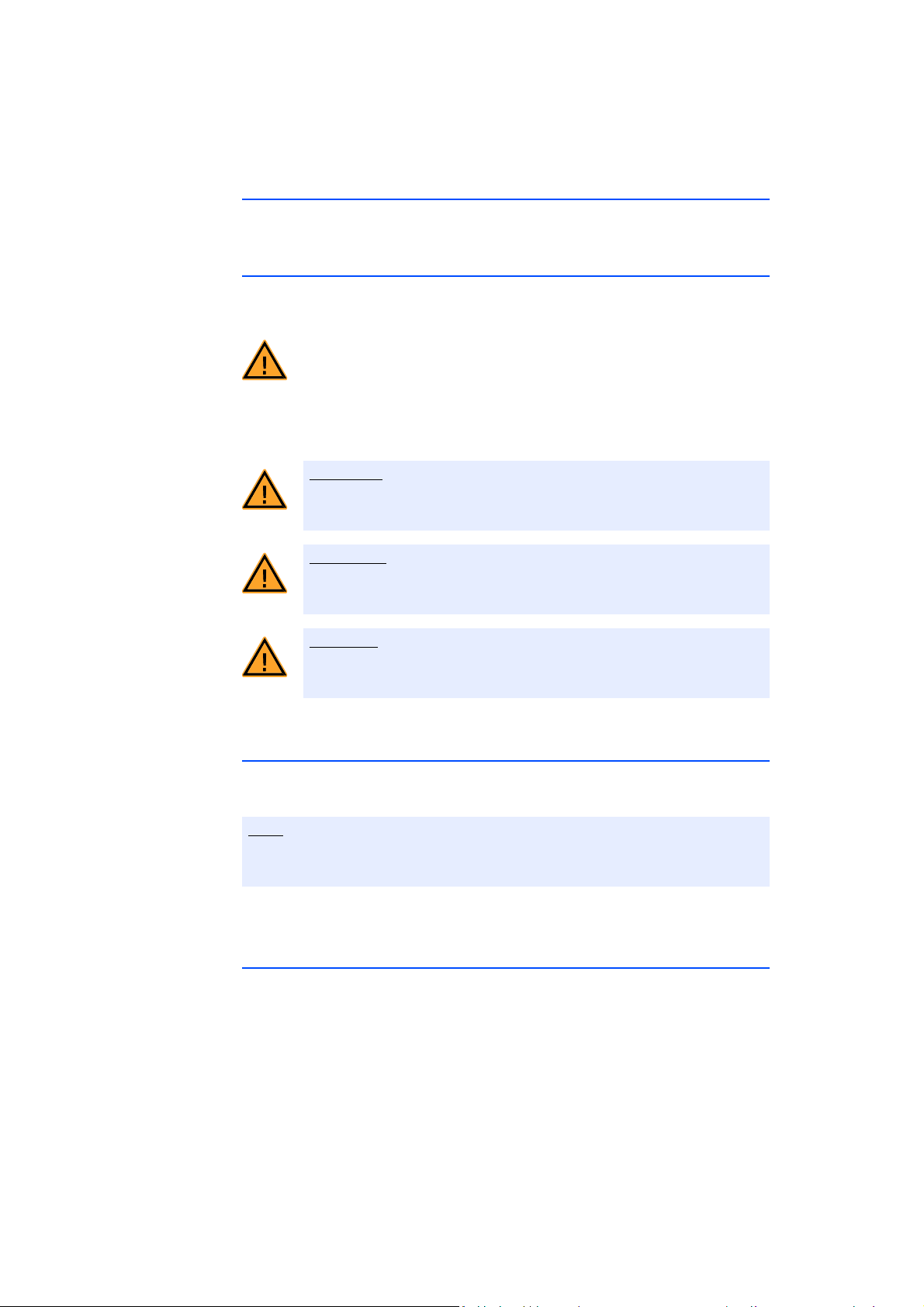
The ES4455.2 Load Carrier Board, the ES4450.3, ES4451.4, ES4452.1,
ES4453.1, ES4457.1 and ES4458.1 are plug-in cards for the ES4408.1 Load
Chassis. With the help of ES5372.1 Carrier for ES4455 Load Boards, the plug-in
cards can also be used in the ES5300.1-A Housing or in the ES5300.1-B Housing.
The ES4455.2 Load Carrier Board consists of the following:
• Slot for a load emulation for simulating injection valves with connections
to ECU output stages
• Digital and analog output interfaces for the ES4408.1 or ES5300.1-A-
based hardware-in-the-loop system or for connecting oscilloscopes or
other measurement devices
• SPI Interface to the ES4408.1 Load Chassis or the ES5300.1-A Housing or
the ES5300.1-B Housing
The ES4450.3, ES4451.4, ES4452.1, ES4453.1, ES4457.1 and ES4458.1 plug-in
cards consist of the following:
• Load emulation for simulating injection valves with connections to ECU
output stages
• Digital and analog output interfaces for the ES4408.1 or ES5300.1-A
based hardware-in-the-loop system or for connecting oscilloscopes or
other measurement devices
• SPI Interface to the ES4408.1 Load Chassis or the ES5300.1-A Housing
and to the ES5300.1-B Housing
The ES4455.2 and its variants ES4450.3, ES4451.4, ES4452.1, ES4453.1,
ES4457.1 and ES4458.1 mounted with load modules may be operated only in
the ES4408.1 Load Chassis, ES5300.1-A Housing and in the ES5300.1-B Hous-
ing.
The intended use of the ES4455.2 and its variants ES4450.3, ES4451.4,
ES4452.1, ES4453.1, ES4457.1 and ES4458.1 mounted with load modules is as
follows:
• Use in industrial lab facilities or workplaces
• Hardware interface for ECUs in a hardware-in-the-loop test system
• Cooperation with ETAS software which supports the ES4408.1 Load
Chassis or ES5300.1-A Housing or the ES5300.1-B Housing
• Interface in cooperation with software programs that operate the stan-
dardized, documented and open APIs of ETAS software products
The ES4455.2 and its variants ES4450.3, ES4451.4, ES4452.1, ES4453.1,
ES4457.1 and ES4458.1 mounted with load modules are not intended to be
used as follows:
• Within a vehicle on the road
• As part of a life support system

ES4455.2 Load Carrier Board - User’s Guide 11
ETAS Introduction
• In applications where misuse can lead to injuries or damages
• In environments in which conditions prevail that fall outside the specified
ranges: see "Ambient Conditions" on page 48
• With signal conditioning that falls outside the specified ranges: see "Tech-
nical Data and Standards" on page 47
Requirements for the Technical State of the Product
The product is designed in accordance with state-of-the-art technology and rec-
ognized safety rules. The product may be operated only in a technically flawless
condition and according to the intended purpose and with regard to safety and
dangers as stated in the respective product documentation. If the product is not
used according to its intended purpose, the protection of the product may be
impaired.
Requirements for Operation
The following requirements are necessary for safe operation:
• Use the product only according to the specifications in the corresponding
User's Guide. With any deviating operation, the product safety is no lon-
ger ensured.
• Do not use the product in a wet or damp environment.
• Do not use the product in potentially explosive atmospheres.
Electrical Safety and Power Supply
Observe the regulations applicable at the operating location concerning electrical
safety as well as the laws and regulations concerning work safety!
WARNING!
Danger from high voltages!
The components, plug connectors and conductor paths of the
ES4455.2 Load Carrier Board and its variants ES4450.3, ES4451.4,
ES4452.1, ES4453.1, ES4457.1 and ES4458.1 may have dangerous
voltages. These voltages can still be present even after the ES4455.2
and its variants ES4450.3, ES4451.4, ES4452.1, ES4453.1, ES4457.1
and ES4458.1 have been removed from the ES4408.1 Load Chassis,
the ES5300.1-A Housing or the ES5300.1-B Housing or if the
ES4408.1 Load Chassis, the ES5300.1-A Housing or the ES5300.1-B
Housing have been switched off.
Make sure that the products are protected from external contact
during operation. Switch off the ES5300.1-A Housing, the ES5300.1-
B Housing or the ES4408.1 Load Chassis and unplug from the mains.
Wait at least three minutes before removing the products.
Failure to do so poses a danger to life and health.

ES4455.2 Load Carrier Board - User’s Guide12
Introduction ETAS
Power Supply
The products are powered by the ES4408.1 Load Chassis via the ES4408.1 Back-
plane Connector or, if mounted in an ES5372.1, via the ES5300.1-A Housing or
ES5300.1-B Housing by the ES5300.1 Backplane Connector.
Insulation Requirements for Lab Power Supplies to Circuits Connected to the HiL
System:
• The power supply to live circuitry must be safely isolated from the supply
voltage. For example, use a car battery or a suitable lab power supply.
• Only use lab power supplies with dual protection for the supply network
(with double/reinforced insulation (DI/RI)). This requirement is met by lab
power supplies that comply with IEC/EN 60950 or IEC/EN 61010.
• The lab power supply must be approved for use at a height of 2000 m and
in ambient temperatures of up to 40 °C.
De-energizing a Plug-in Board
Switch off the ES4408.1 Load Chassis or the ES5300.1-A Housing or ES5300.1-
B Housing and connected power supplies, and unplug the power plug and other
connectors attached to the plug-in board. Wait at least three minutes before
removing the plug-in board.
WARNING!
Danger - electromagnetic radiation!
During operation, the ES4455.2 Load Carrier Board and its populated
variants ES4450.3, ES4451.4, ES4452.1, ES4453.1, ES4457.1 and
ES4458.1 and loads connected to them, can emit electromagnetic
radiation, which can cause cardiac pacemakers or implanted defibril-
lators to malfunction or become damaged.
The products may only be operated in areas where persons with
pacemakers are prohibited from entering. The entrances to these
areas must bear sign P007 "No access for persons with cardiac pace-
makers or implanted defibrillators" in a clearly visible position in
accordance with ISO 7010:2011 "Registered Safety Signs".
Failure to observe this rule can lead to health hazards and even death
for persons with pacemakers and implanted defibrillators.
WARNING!
Fire hazard!
Use only fuses that meet the specification in Tab. 2-1 on page 31!
Never bridge defective fuses!
Failure to observe the fuse specification can lead to excess currents,
short circuits and fires.

ES4455.2 Load Carrier Board - User’s Guide 13
ETAS Introduction
Approved Cables
The signal lines must not exceed a maximum length of 3 m.
Requirements for the Installation Location
Requirements for Ventilation
Transport and Installation
To avoid damages to the hardware from electrostatic discharge, please observe
the following precautionary measures:
WARNING!
Fire hazard!
Use only approved cables for creating cable assemblies (e.g. for con-
necting the ECU and external loads). The cables used must be suitable
particularly for occurring currents, voltages and temperatures and
flame-retardant in accordance with one of the following standards
IEC 60332-1-2, IEC 60332-2-2, UL 2556/UL1581VW-1!
WARNING!
This is class A equipment. This equipment can cause radio interfer-
ence in residential areas. Should that be the case, the operator may
be requested to institute reasonable measures.
CAUTION!
The air circulation inside the ES4408.1 Load Chassis, the ES5300.1-A
housing and the ES5300.1-B housing can be ensured only if all free
slots are covered with front plates. Otherwise, it may lead to overtem-
peratures and trip the overtemperature protection of the ES5300.1-A
or the ES5300.1-B. For this reason, install front plates in all free slots!
CAUTION!
Some components of the ES4455.2 Load Carrier Board and its vari-
ants ES4450.3, ES4451.4, ES4452.1, ES4453.1, ES4457.1 and
ES4458.1 can be damaged or destroyed through electrostatic dis-
charges. Leave the plug-in card in its transport packaging until its
installation. The ES4455.2 Load Carrier Board and its variants
ES4450.3, ES4451.4, ES4452.1, ES4453.1, ES4457.1 and ES4458.1
may be removed from the transport packaging, configured and
installed only at a workplace that is well secured against static dis-
charges.

ES4455.2 Load Carrier Board - User’s Guide14
Introduction ETAS
Connecting/Disconnecting Devices
To avoid injuries and hardware damages, observe the following precautionary
measures:
• Do not apply any voltages to the connections of the products that do not
correspond to the specifications of the respective connection.
• Do not connect or disconnect any devices while the ES4408.1 Load Chas-
sis, the ES5300.1-A Housing or ES5300.1-B Housing or connected devices
are switched on. First, switch off the ES4408.1 Load Chassis, the
ES5300.1-A Housing or ES5300.1-B Housing by shutting down the real-
time PC and by activating the On/Off switch at the rear and unplug the
power cable.
• When plugging in connectors, ensure that they are inserted straight and
no pins are bent.
Maintenance
The product does not require maintenance.
Repairs
If an ETAS hardware product needs to be repaired, return the product to ETAS.
Cleaning
The product is not expected to require cleaning.
CAUTION!
In order to prevent damage to the plug-in boards and the LABCAR
housing, and thereby also avoid damage to property or health,
observe the installation instructions and information contained in the
relevant User's Guides.
CAUTION!
If cards (e.g. for startup or calibration) are unlocked but not com-
pletely removed from the housing, they must be pulled out far
enough that the distance between the respective card and the back-
plane of the housing is at least 1 cm. Otherwise, contacts may be
established between the cards and lead to their destruction.

ES4455.2 Load Carrier Board - User’s Guide 15
ETAS Introduction
1.3 Identifications on the Product
The Following Symbols are Used for Product Labeling:
Please observe the information in the chapter "Technical Data and Standards"
on page 47.
1.3.1 CE Mark
With the CE marking attached to the product or its packaging, ETAS confirms
that the product corresponds to the product-specific, applicable European Direc-
tives. The CE Declaration of Conformity for the product is available upon request.
1.3.2 KC Mark
With the KC mark attached to the product and its packaging, ETAS confirms that
the product has been registered in accordance with the product-specific KCC
guidelines of the Republic of Korea.
Symbol Description
The User's Guide must be read prior to the startup of the
product
Marking for CE conformity
(see "CE Mark" on page 15)
Marking for KCC conformity
(see "KC Mark" on page 15)
Only for ES4452.1 and ES4457.1
Marking for China RoHS, see chapter
(see "RoHS Conformity" on page 16)
Marking for conformity with WEEE directive
(see "Product Return and Recycling" on page 16)
Identification in accordance with ISO 7010:2011, P007: "No
access for persons with pacemakers and implanted defibrilla-
tors."
"Operational malfunction or damage to pacemakers and
implanted defibrillators".

ES4455.2 Load Carrier Board - User’s Guide16
Introduction ETAS
1.3.3 RoHS Conformity
European Union
The EU guideline 2011/65/EU limits the use of certain dangerous materials for
electric and electronic devices (RoHS conformity).
ETAS confirms that the product meets this directive applicable in the European
Union.
China
With the China RoHS identification attached to the product or its packaging,
ETAS confirms that the product meets the guidelines of the "China RoHS" (Man-
agement Methods for Controlling Pollution Caused by Electronic Information
Products Regulation) applicable in the People's Republic of China.
1.3.4 Identification in Accordance with ISO 7010:2011
Under consideration of the standard ISO 7010:2011, the product is labeled with
the symbol P007: "No access to persons with pacemakers or implanted defibril-
lators".
The products may be used only in areas to which persons with pacemakers and
implanted defibrillators have no access. The user is obligated to attach a label in
accordance with ISO 7010:2011, P007: "No access to persons with pacemakers
or implanted defibrillators", to the entrances to the areas in which the product is
used.
1.4 Product Return and Recycling
The European Union (EU) released the Directive for Waste Electrical and Elec-
tronic Equipment - WEEE to ensure the setup of systems for collecting, treating
and recycling electronic waste in all countries of the EU.
This ensures that the devices are recycled in a resource-friendly way that does not
represent any risk to personal health and the environment.
Fig. 1-3 WEEE symbol
The WEEE symbol on the product or its packaging identifies that the product may
not be disposed of together with the remaining trash.
The user is obligated to separately collect old devices and provide them to the
WEEE return system for recycling.
The WEEE Directive applies to all ETAS devices, but not to external cables or bat-
teries.
Additional information about the recycling program of ETAS GmbH is available
from the ETAS sales and service locations (see "ETAS Contact Addresses"
on page 51).

ES4455.2 Load Carrier Board - User’s Guide 17
ETAS Introduction
1.5 Materials Subject to Declaration
Some products from ETAS GmbH (e.g. modules, boards, cables) use components
with materials that are subject to declaration in accordance with the REACH reg-
ulation (EC) no.1907/2006.
Detailed information is located in the ETAS download center in the customer
information "REACH Declaration" < www.etas.com/Reach >. This information is
continuously being updated.

ES4455.2 Load Carrier Board - User’s Guide18
Introduction ETAS
1.6 About this Manual
This manual consists of the following chapters:
• "Introduction" on page 5
This chapter.
• "Design of an Injector Simulation Environment" on page 21
This chapter describes how the ES4455.2 Load Carrier Board and its vari-
ants ES4450.3, ES4451.4, ES4452.1, ES4453.1, ES4457.1 and
ES4458.1mounted with load modules can be integrated in a LABCAR HiL
system.
• "Properties and Functions" on page 21
This chapter features a description of the properties and functions of the
components of the ES4455.2 Load Carrier Board and its variants
ES4450.3, ES4451.4, ES4452.1, ES4453.1, ES4457.1 and ES4458.1
mounted with load modules.
• "Connections and Connectors" on page 37
This chapter describes the connections of the ES4455.2 Load Carrier
Board and its variants ES4450.3, ES4451.4, ES4452.1, ES4453.1,
ES4457.1 and ES4458.1 that are mounted with load modules.
• "Technical Data and Standards" on page 47
This chapter contains information about the technical data and standards
of the products.
• "Ordering Data and Scope of Delivery" on page 49
1.6.1 Working with this Manual
Presentation of Information
All activities to be performed by the user are presented in a "Use Case" format.
That is, the goal to be accomplished is briefly defined in the heading, and the
respective steps required for reaching this goal are then presented in a list. The
presentation looks as follows:
Target definition
any advance information...
1. Step 1
Any explanation for step 1...
2. Step 2
Any explanation for step 2...
Any concluding comments...
Specific example:
Creating a new file
Before creating a new file, no other file may be open.
1. Select File → New.
The "Create File" dialog box appears.

ES4455.2 Load Carrier Board - User’s Guide 19
ETAS Introduction
2. Enter the name for the file in the "File Name" field.
The file name may not have more than 8 characters.
3. Click on OK.
The new file is being created and saved under the name you specified. You can
now work with the file.
Typographical Conventions
The following typographical conventions are used:
Important notes for the user are presented as follows:
Select File →Open. Menu commands are displayed in bold/
blue.
Click on OK. Buttons are displayed in bold/blue.
Press <ENTER>. Key commands are printed in small capi-
tals enclosed in angle brackets.
The "Open File" dialog window
appears.
Names of program windows, dialog win-
dows, fields and similar are given in quota-
tion marks.
Select the setup.exe file. Text in selection lists, program code, as
well as path and file names are displayed
using the Courier font.
A conversion between the logical
and arithmetic data types is not
possible.
Content-based highlights and newly intro-
duced terms are placed in italics.
Note
Important note for the user.

ES4455.2 Load Carrier Board - User’s Guide20
Introduction ETAS
This manual suits for next models
6
Table of contents
Other ETAS Control Unit manuals

ETAS
ETAS ES585.1 User manual

ETAS
ETAS ES441.1 User manual

ETAS
ETAS ES430.1 User manual

ETAS
ETAS ES584.1 User manual

ETAS
ETAS FETK-T5.0A User manual

ETAS
ETAS ES5385.1 User manual

ETAS
ETAS FlexRay ES920.1 User manual

ETAS
ETAS XETK-V2.0 Series User manual

ETAS
ETAS ES313.1 User manual

ETAS
ETAS ES511.1 User manual
Popular Control Unit manuals by other brands

Panasonic
Panasonic INDUSTRY PAN9028 Integration guide

EB TECHNOLOGY
EB TECHNOLOGY START S10 manual

Ross
Ross SideBox Installation and setup

Texas Instruments
Texas Instruments TLV320AIC3109EVM-K user guide

resideo
resideo BA295S installation instructions

Moxa Technologies
Moxa Technologies NE-4100 Series user manual