VMIC VMIVME-7455 User manual
Artisan Technology Group is your source for quality
new and certied-used/pre-owned equipment
• FAST SHIPPING AND
DELIVERY
• TENS OF THOUSANDS OF
IN-STOCK ITEMS
• EQUIPMENT DEMOS
• HUNDREDS OF
MANUFACTURERS
SUPPORTED
• LEASING/MONTHLY
RENTALS
• ITAR CERTIFIED
SECURE ASSET SOLUTIONS
SERVICE CENTER REPAIRS
Experienced engineers and technicians on staff
at our full-service, in-house repair center
WE BUY USED EQUIPMENT
Sell your excess, underutilized, and idle used equipment
We also offer credit for buy-backs and trade-ins
www.artisantg.com/WeBuyEquipment
REMOTE INSPECTION
Remotely inspect equipment before purchasing with
our interactive website at www.instraview.com
LOOKING FOR MORE INFORMATION?
Visit us on the web at www.artisantg.com for more
information on price quotations, drivers, technical
specications, manuals, and documentation
Contact us: (888) 88-SOURCE | sales@artisantg.com | www.artisantg.com
SM
View
Instra

12090 South Memorial Parkway
Huntsville, Alabama 35803-3308, USA
(256) 880-0444 w(800) 322-3616 wFax: (256) 882-0859
VMIVME-7455
Single-Slot VMEbus CD-ROM Drive
Module
Installation Guide
522-007455-000 Rev. A
October 05, 1999
Artisan Technology Group - Quality Instrumentation ... Guaranteed | (888) 88-SOURCE | www.artisantg.com

12090 South Memorial Parkway
Huntsville, Alabama 35803-3308, USA
(256) 880-0444 w(800) 322-3616 wFax: (256) 882-0859
Artisan Technology Group - Quality Instrumentation ... Guaranteed | (888) 88-SOURCE | www.artisantg.com

© Copyright 1999. The information in this document has been carefully checked and is believed to be entirely reliable.
While all reasonable efforts to ensure accuracy have been taken in the preparation of this manual, VMIC assumes no
responsibility resulting from omissions or errors in this manual, or from the use of information contained herein.
VMIC reserves the right to make any changes, without notice, to this or any of VMIC’s products to improve reliability,
performance, function, or design.
VMIC does not assume any liability arising out of the application or use of any product or circuit described herein; nor
does VMIC convey any license under its patent rights or the rights of others.
For warranty and repair policies, refer to VMIC’s Standard Conditions of Sale.
AMXbus, BITMODULE, COSMODULE, DMAbus, Instant OPC wizard logo, IOWorks Access, IOWorks Foundation,
IOWorks man figure, IOWorks Manager, IOWorks Server, MAGICWARE, MEGAMODULE, PLC ACCELERATOR
(ACCELERATION), Quick Link, RTnet, Soft Logic Link, SRTbus, TESTCAL, “The Next Generation PLC”, The PLC
Connection, TURBOMODULE, UCLIO, UIOD, UPLC, Visual Soft Logic Control(ler),
VMEaccess
,
VMEmanager
,
VMEmonitor
, VMEnet, VMEnet II, and
VMEprobe
are trademarks. The I/O Experts, The I/O Systems Experts, The Soft
Logic Experts, and The Total Solutions Provider are service marks of VMIC.
COPYRIGHT AND TRADEMARKS
VMIC
All Rights Reserved
This document shall not be duplicated, nor its contents used for any
purpose, unless granted express written permission from VMIC.
The I/O man figure, IOWorks, UIOC, Visual IOWorks, and
WinUIOC
are registered trademarks of VMIC.
ActiveX is a trademark. Microsoft, Microsoft Access, MS-DOS, Visual Basic, Visual C++, Win32, Windows,
Windows NT, and XENIX are registered trademarks of Microsoft Corporation.
MMX is a trademark and Celeron is a registered trademark of Intel Corporation.
PICMG and CompactPCI are registered trademarks of PCI Industrial Computer Manufacturers’ Group.
Other registered trademarks are the property of their respective owners.
(I/O man figure) (IOWorks man figure)(Instant OPC wizard logo)
Artisan Technology Group - Quality Instrumentation ... Guaranteed | (888) 88-SOURCE | www.artisantg.com

12090 South Memorial Parkway
Huntsville, Alabama 35803-3308, USA
(256) 880-0444 w(800) 322-3616 wFax: (256) 882-0859
Artisan Technology Group - Quality Instrumentation ... Guaranteed | (888) 88-SOURCE | www.artisantg.com

5
Installation Procedures
Contents
Installation of theVMIVME-7455 with the VMIVME-7589, or the VMIVME-7589A . . . .. . . . . . . . . . .. 9
Installation of the VMIVME-7455with the VMIVME-7591, VMIVME-7592, or the VMIVME-7695. 11
Installation of theVMIVME-7455 with the VMIVME-7696 . . . . . . . . . . . .. . . . . . . . . . .. . . . . . . . . . . .. . . . . 12
Board P1 Connector Pinout .. . . . . . . . . . . . . .. . . . . . . . . . .. . . . . . . . . . .. . . . . . . . . . . .. . . . .. . . . . . . . . . . .. . . . . 14
Board P2 Connector Pinout .. . . . . . . . . . . . . .. . . . . . . . . . .. . . . . . . . . . .. . . . . . . . . . . .. . . . .. . . . . . . . . . . .. . . . . 15
Introduction
The VMIVME-7455 is designed to interface with VMIC’s PC/AT family of CPU
products. A 6U single-slot VMEbus passive board, that contains a 24x Multisession
photo CD-ROM drive, compatible with CD-I, Video CD, Enhanced CD, and CD
PLUS. CPU boards connect to the VMIVME-7455 by way of the P2 connector on the
VMEbus backplane. The VMIVME-7455 is also compatible with VMIC’s
VMIVME-7452 Single-Slot VMEbus Floppy/Hard Disk Module with Flash Memory.
A diagram of the VMIVME-7455 is shown in Figure 1 on page 6.
Three separate procedures are outlined in this installation guide:
1. Installation of the VMIVME-7455 with the VMIVME-7589, or -7589A CPU.
2. Installation of the VMIVME-7455 with the VMIVME-7591, -7592, or the -7695*.
3. Installation of the VMIVME-7455 with the VMIVME-7696 CPU.
*The VMIVME-7695 (VME64) is only compatible with the VMIVME-7455 if used in a
standard VMEbus chassis with the shrouded P2 96-pin backplane connectors.
The VMIVME-7455 is factory configured and supported only as a IDE Slave device.
Artisan Technology Group - Quality Instrumentation ... Guaranteed | (888) 88-SOURCE | www.artisantg.com
6
VMIVME-7455 Single-Slot VMEbus CD-ROM Drive Module
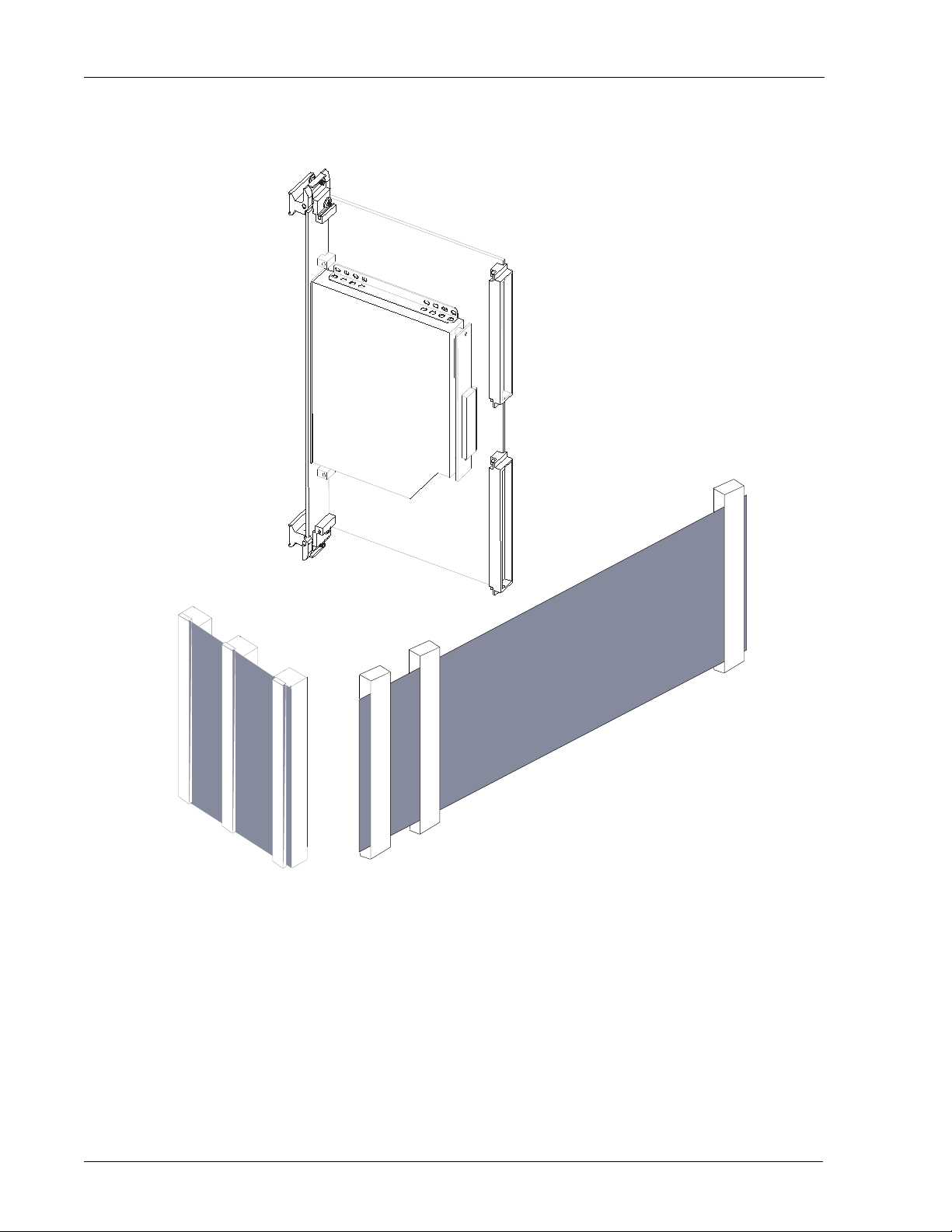
Figure 1 VMIVME-7455 and Cables
VMIVME-7455
64-Conductor
VMIC Cable Assembly
Model#VMIVME-VMXC-3
64-Conductor
VMIC Cable Assembly
Model#VMIVME-VMXC-7
Artisan Technology Group - Quality Instrumentation ... Guaranteed | (888) 88-SOURCE | www.artisantg.com

7
Figure 2 VMIVME-7455 Board Layout
discisc
compact
VMIVME
7455
Artisan Technology Group - Quality Instrumentation ... Guaranteed | (888) 88-SOURCE | www.artisantg.com
8
VMIVME-7455 Single-Slot VMEbus CD-ROM Drive Module
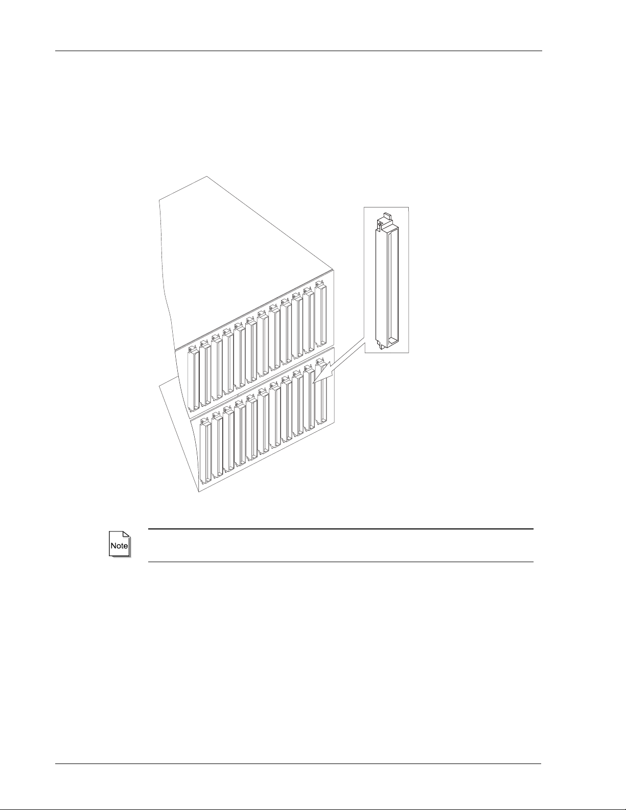
The VMIVME-7455 utilizes the P2 connectors on the VMEbus Backplane rear I/O for
the routing of all signals. All IDE signals are routed from the CPU to the
VMIVME-7455 by way of 64-conductor cable assemblies, using flat ribbon cables (see
figure below for a typical VMEbus backplane and shrouded connectors). See “Board
P2 Connector Pinout” on page 15 for the P2 connector.
VMIC recommends the use of backplanes with the shrouded type backplane
connectors. The shrouded connectors provide stability and the proper pin alignment.
Figure 3 VMEbus Chassis with Shrouded Connectors
Artisan Technology Group - Quality Instrumentation ... Guaranteed | (888) 88-SOURCE | www.artisantg.com

9
Installation of the VMIVME-7455 with the VMIVME-7589, or the VMIVME-7589A
Installation of the VMIVME-7455 with the VMIVME-7589, or the
VMIVME-7589A
The VMIVME-7455 receives and passes IDE signals by way of the P2 connector,
routed through the backplane from the following CPUs: VMIVME-7589 and
VMIVME-7589A. To utilize the P2 configuration, a backplane which supports I/ O
cabling from the rear must be used, along with a 64-conductor cable assembly (VMIC
Model Number VMIVME-VMXC-3), see Figure 4 below. Figure 5 on page 10 is an
illustration of the installation. The cable is supplied with the VMIVME-7455. Figure 4
shows the cable used with the VMIVME-7589, or the VMIVME-7589A.
When installing the VMIVME-7589, or the -7589A with the VMIVME-7455, and the
optional VMIVME-7452, the boards must be installed in consecutive slots. Under
certain conditions the system may require a longer cable, this cable is available as
(VMIC Model Number VMIVME-VMXC-7), see Figure 7 on page 12.
The P2 connection to the VMIVME-7589, or the VMIVME-7589A involves the
following board configuration:
1. Ensure that jumper J12 on the VMIVME-7589, or the VMIVME-7589A is
configured to route the signals to the P2 connector. A jumper shunt should be
installed on pins 2 and 3, to utilize the P2 connector. Refer to the Product
Manuals for the jumper configuration.
2. Insert the CPU into the desired slot.
3. Insert the VMIVME-7455 into the desired slot.
4. Install the 64-conductor cable assembly onto the rear of the backplane. The cable
must be connected to the rear I/O shrouded P2 connectors of both slots. One
occupied by the VMIVME-7589, or the VMIVME-7589A and the other connected
to the VMIVME-7455 P2 connector.
Figure 4 64-Conductor Cable Assembly (Model No. VMIVME-VMXC-3)
Connector Side
Cable Side
Artisan Technology Group - Quality Instrumentation ... Guaranteed | (888) 88-SOURCE | www.artisantg.com
10
VMIVME-7455 Single-Slot VMEbus CD-ROM Drive Module
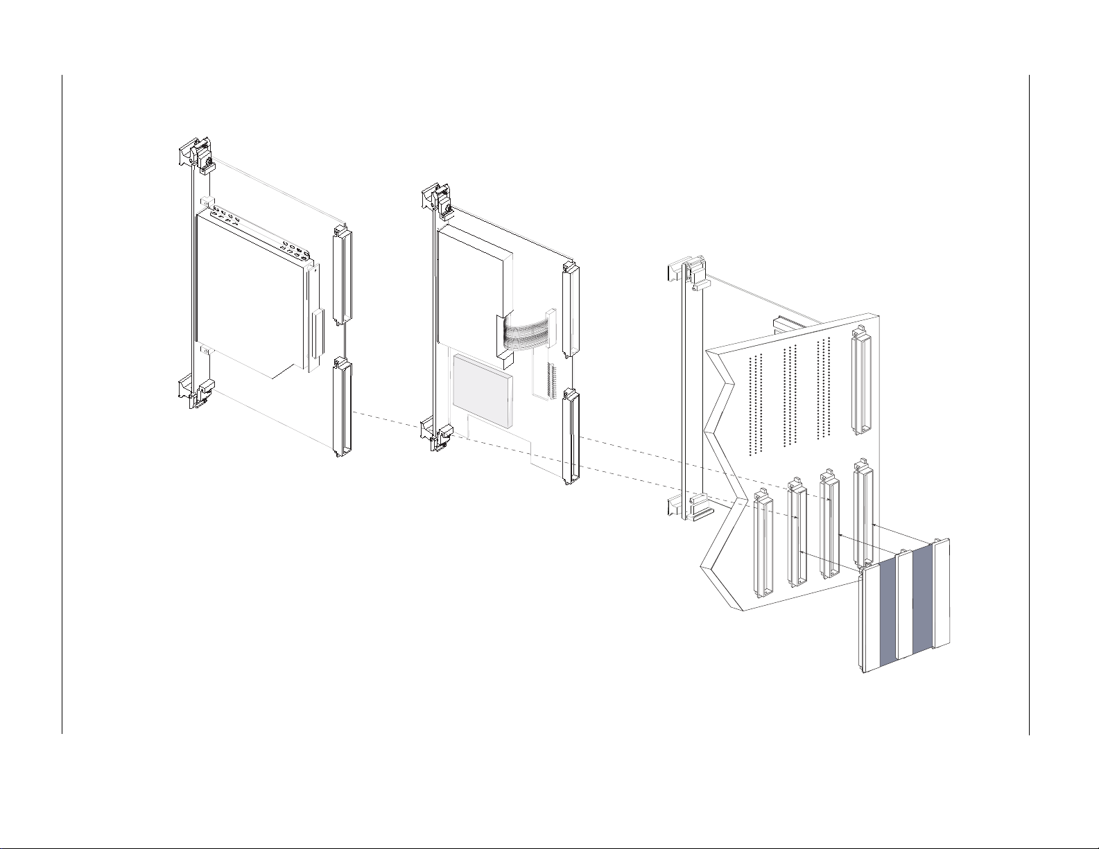
Figure 5 Installation of the VMIVME-7455 with VMIC’s VMIVME-7589, -7589A CPU Products, and the Optional
VMIVME-7452
64-Conductor Cable Assembly
(Model No.VMIVME-VMXC-3)
VMEbus
Backplane
VMIVME-7455
CD ROM
Module (Optional)
VMIVME-7452
Floppy/Hard Disk
Module
VMIVME-7589
Single-Slot Pentium
Processor-Based CPU
P1
P2
Artisan Technology Group - Quality Instrumentation ... Guaranteed | (888) 88-SOURCE | www.artisantg.com
11
Installation of the VMIVME-7455 with the VMIVME-7591, VMIVME-7592, or the VMIVME-7695
Installation of the VMIVME-7455 with the VMIVME-7591, VMIVME-7592,
or the VMIVME-7695
The installation of the VMIVME-7455 with the VMIVME-7591, -7592, or the -7695 is
similar to the installation on the previous pages. The only exception is that the
VMIVME-7695 is a VME64 compatible product. It is recommended that the
VMIVME-7455 and the VMIVME-7695 be used in a standard VMEbus chassis.
However, if it is a requirement to use a VME64 chassis, the VME64 backplane uses
160-pin 5 row connectors, of which only the center three rows of the backplane pins
are utilized for signals, power, and ground. Therefore, when installing the
VMIVME-7455 in a VME64 chassis, care must be taken to ensure the correct
alignment. Use the 64-conductor cable assembly as identified in Figure 4 on page 9 to
connect the CPU board to the CD ROM and the optional VMIVME-7452 through the
backplane. The same 64-conductor cable assembly should be used for both the
VMEbus and VME64 backplanes. The interface cable part number is VMIC Model
Number VMIVME-VMXC-3.
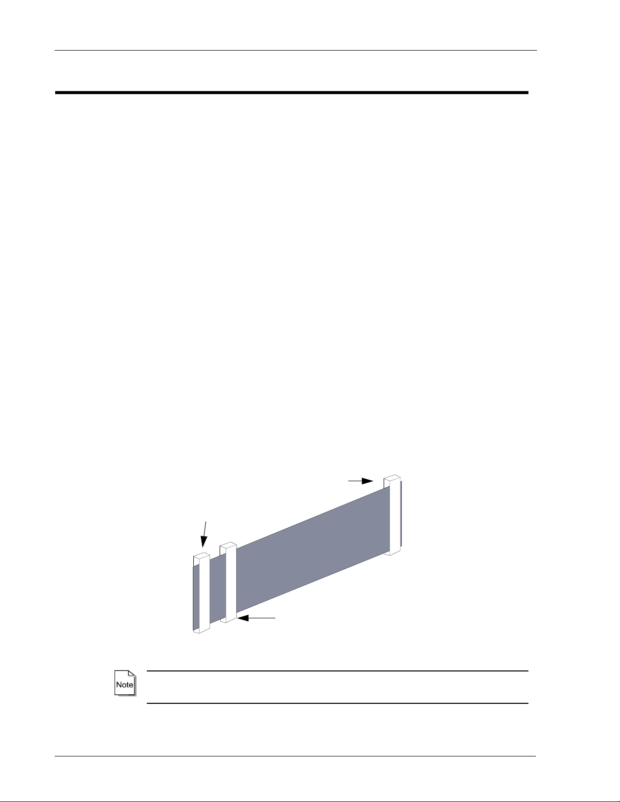
Figure 6 VME64 Backplane with 64-Conductor Cable Assembly
When placing the cable on the backplane ensure that only the center three rows of the
VME64 shrouded connector are used.
VME64 Backplane
64-Conductor Cable Assembly
(Model No. VMIVME-VMXC-3)
P2
Connector
(VME64 5 Rows)
Artisan Technology Group - Quality Instrumentation ... Guaranteed | (888) 88-SOURCE | www.artisantg.com
12
VMIVME-7455 Single-Slot VMEbus CD-ROM Drive Module
Installation of the VMIVME-7455 with the VMIVME-7696
The VMIVME-7696 is a two board set that offers P2 I/O connections for the SCSI, IDE
and Floppy interfaces. The VMIVME-7696 SCSI signals are located on the Daughter
card ‘P2 connector’, with the IDE and Floppy interface on the Motherboard ‘P2
connector’. The VMIVME-7696 is compatible with VMIC’s VMIACC-0561 (VMEbus
P2 transition board), for routing the SCSI signals to a standard 68-pin Ultra-SCSI-2
connector. The VMIVME-7696 utilizes VMIC Model Number VMIVME-VMXC-7
which is a different cable from the one used by other CPU products. The added length
between the connector intended for the CPU’s motherboard and the middle connector
allows routing of the cable when the VMIACC-0561 is installed. The following is the
procedure used to install the VMIVME-7696 and the VMIVME-7455:
1. Insert the VMIVME-7696 CPU board into the desired slot of the VMEbus chassis.
2. Insert the VMIVME-7455 and the optional VMIVME-7452 into the desired slots
of the VMEbus chassis.
3. Connect the 64-conductor cable assembly to the extended pins of the P2
connectors located on the rear of the backplane.
3a. The cable must be installed into the slot occupied by the CPU’s
motherboard.
3b. The other end of the cable must be installed into the slot occupied by the
VMIVME-7455.
3c. If a VMIVME-7452 is to be used, install the connector located in the
middle of the 64-conductor cable assembly into the corresponding slot.
Figure 8 on page 13 illustrates the installation of the VMIVME-7696 with the
VMIVME-7455, and the optional VMIVME-7452.
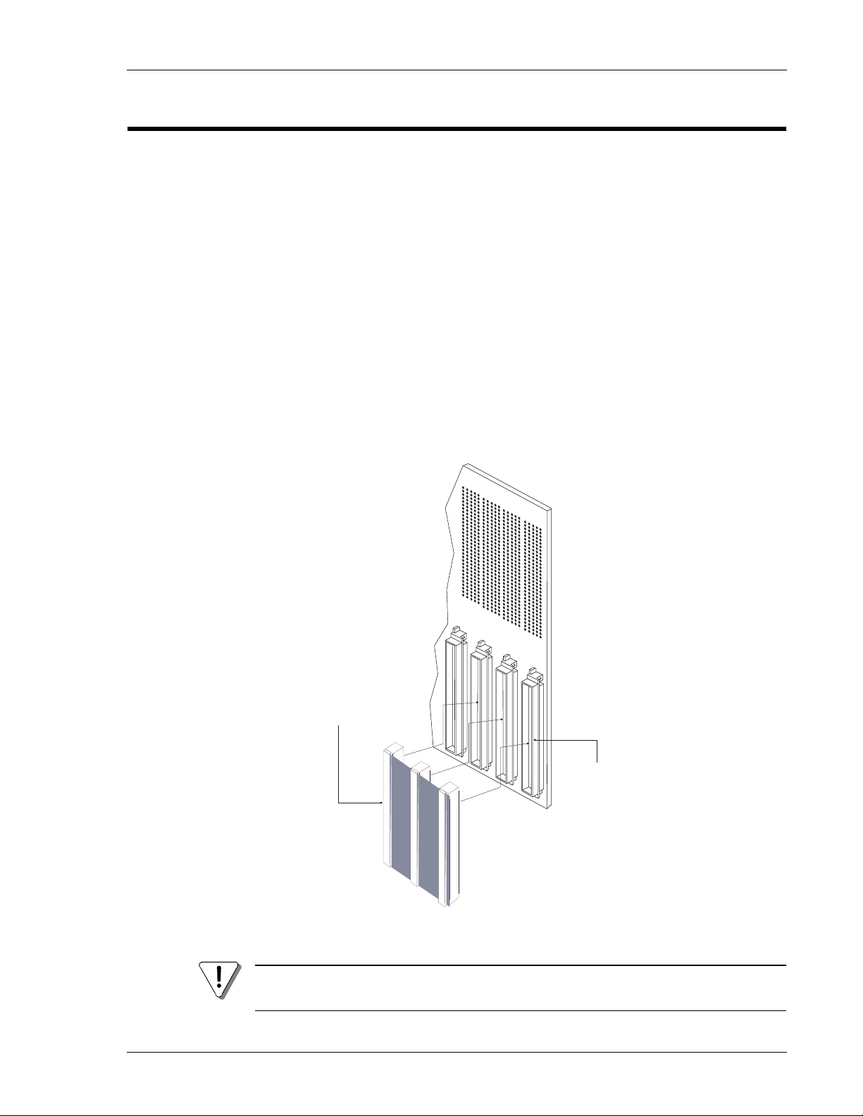
Figure 7 64-Conductor Cable Assembly (Model No. VMIVME-VMXC-7)
The VMIVME-7696, -7455, and the -7452 do not have to be in consecutive slots in the
VMEbus chassis.
To CPU P2
Motherboard
To Optional
To VMIVME-7455
Board (Step 3b)
(Step 3a)
VMIVME-7452 (Step 3c)
Connector
Artisan Technology Group - Quality Instrumentation ... Guaranteed | (888) 88-SOURCE | www.artisantg.com
13
Installation of the VMIVME-7455 with the VMIVME-7696
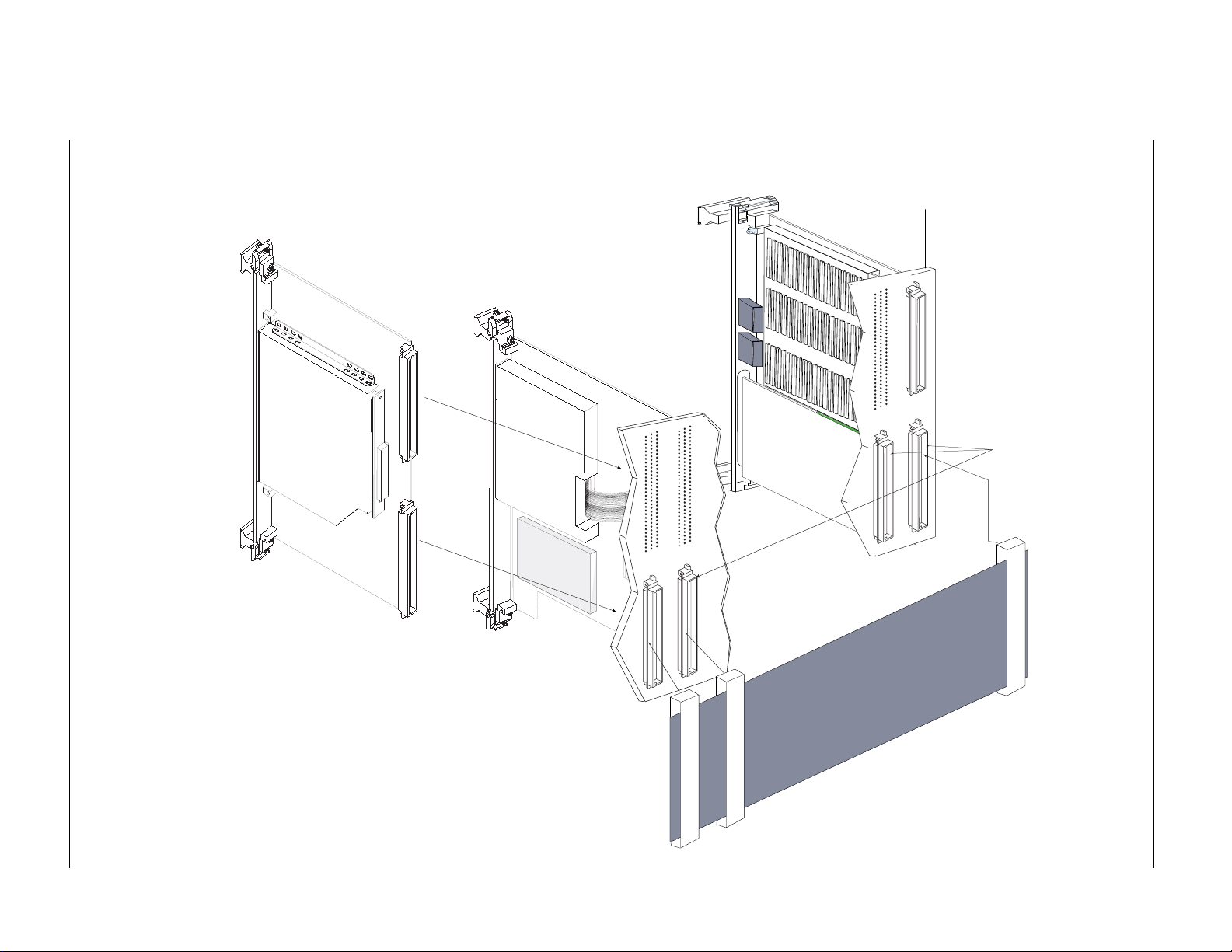
Figure 8 Connecting a VMIVME-7455 to a VMIVME-7696 with the Optional VMIVME-7452
P2
Connectors
VMIVME-7455
CD ROM
Module
VMIVME-7452
Floppy/Hard Disk
Module w/Flash Memory (Optional)
VMIVME-7696
CPU Module
64-Conductor Cable
Assembly
VMEbus
Backplane
Artisan Technology Group - Quality Instrumentation ... Guaranteed | (888) 88-SOURCE | www.artisantg.com
14
VMIVME-7455 Single-Slot VMEbus CD-ROM Drive Module
Board P1 Connector Pinout
Figure 9 P1 Connector and Pinout
Pin No. Row C Row B Row A
1N/C N/C N/C
2N/C N/C N/C
3N/C N/C N/C
4N/C BG0OUT* N/C
5N/C BG0IN* N/C
6N/C BG1OUT* N/C
7N/C BG1IN* N/C
8N/C BG2OUT* N/C
9 GND BG2IN* GND
10 N/C BG3OUT* N/C
11 N/C BG3IN* GND
12 N/C N/C N/C
13 N/C N/C N/C
14 N/C N/C N/C
15 N/C N/C GND
16 N/C N/C N/C
17 N/C N/C GND
18 N/C N/C N/C
19 N/C N/C GND
20 N/C GND N/C
21 N/C N/C IACKOUT*
22 N/C N/C IACKIN*
23 N/C GND N/C
24 N/C N/C N/C
25 N/C N/C N/C
26 N/C N/C N/C
27 N/C N/C N/C
28 N/C N/C N/C
29 N/C N/C N/C
30 N/C N/C N/C
31 N/C N/C N/C
32 +5 V +5 V +5 V
Pin# 32
C B A
Pin# 1
Artisan Technology Group - Quality Instrumentation ... Guaranteed | (888) 88-SOURCE | www.artisantg.com

15
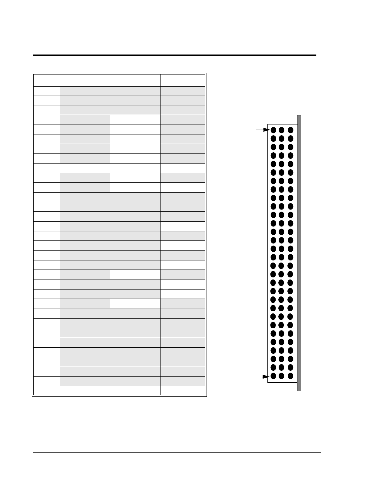
Board P2 Connector Pinout
Board P2 Connector Pinout
Figure 10 P2 Connector and Pinout
Use only the 96 position, 64-conductor ribbon cables
Pin No. Row C Row B Row A
1RESET* +5V GND
2 DD7 GND DD8
3 DD6 N/C DD9
4 DD5 N/C DD10
5 DD4 N/C DD11
6 DD3 N/C DD12
7 DD2 N/C DD13
8 DD1 N/C DD14
9 DD0 N/C DD15
10 IOCS16* N/C DMARQ*
11 GND N/C DIOW*
12 GND GND DIOR*
13 GND +5 V IORDY
14 CSEL N/C GND
15 DMACK* N/C GND
16 INTRQ N/C GND
17 DA2 N/C DA1
18 DA0 N/C CS0*
19 CS1* N/C DASP*
20 N/C N/C N/C
21 N/C N/C GND
22 N/C GND N/C
23 N/C N/C GND
24 N/C N/C GND
25 N/C N/C GND
26 N/C N/C GND
27 N/C N/C GND
28 N/C N/C GND
29 N/C N/C N/C
30 N/C N/C GND
31 N/C GND +5 V
32 N/C +5 V +5 V
Pin# 32
C B A
Pin# 1
Artisan Technology Group - Quality Instrumentation ... Guaranteed | (888) 88-SOURCE | www.artisantg.com

16
VMIVME-7455 Single-Slot VMEbus CD-ROM Drive Module
Artisan Technology Group - Quality Instrumentation ... Guaranteed | (888) 88-SOURCE | www.artisantg.com

17
Maintenance
Maintenance
This section provides information relative to the care and maintenance of VMIC’s
products. If the products malfunction, verify the following:
•Software
• System configuration
• Electrical connections
• Jumper or configuration options
• Boards are fully inserted into their proper connector location
• Connector pins are clean and free from contamination
• No components of adjacent boards are disturbed when inserting or removing
the board from the chassis
• Quality of cables and I/O connections
If products must be returned, contact VMIC for a Return Material Authorization
(RMA) Number. This RMA Number must be obtained prior to any return.
Artisan Technology Group - Quality Instrumentation ... Guaranteed | (888) 88-SOURCE | www.artisantg.com

VMIVME-7455 Single Slot VMEbus CD-ROM Drive Module
18
Maintenance Prints
User level repairs are not recommended. The appendix to this manual contains
drawings and diagrams for reference purposes only.
Artisan Technology Group - Quality Instrumentation ... Guaranteed | (888) 88-SOURCE | www.artisantg.com

Artisan Technology Group is your source for quality
new and certied-used/pre-owned equipment
• FAST SHIPPING AND
DELIVERY
• TENS OF THOUSANDS OF
IN-STOCK ITEMS
• EQUIPMENT DEMOS
• HUNDREDS OF
MANUFACTURERS
SUPPORTED
• LEASING/MONTHLY
RENTALS
• ITAR CERTIFIED
SECURE ASSET SOLUTIONS
SERVICE CENTER REPAIRS
Experienced engineers and technicians on staff
at our full-service, in-house repair center
WE BUY USED EQUIPMENT
Sell your excess, underutilized, and idle used equipment
We also offer credit for buy-backs and trade-ins
www.artisantg.com/WeBuyEquipment
REMOTE INSPECTION
Remotely inspect equipment before purchasing with
our interactive website at www.instraview.com
LOOKING FOR MORE INFORMATION?
Visit us on the web at www.artisantg.com for more
information on price quotations, drivers, technical
specications, manuals, and documentation
Contact us: (888) 88-SOURCE | sales@artisantg.com | www.artisantg.com
SM
View
Instra
Other VMIC Control Unit manuals


