Voith BTG MEK-3000 User manual

User Manual
MEK-3000
Rotating Consistency Transmitter

Copyright© 2021 BTG Instruments AB
The contents of this document are subject to revision without notice due to continued progress
in methodology, design, and manufacturing. BTG shall have no liability for any error or
damages of any kind resulting from the use of this document.
All rights reserved. No part of this document may be copied, photocopied, published,
reproduced, translated or converted into electronic or machine-readable form
without written permission of BTG Instruments AB.
Original Instructions
BTG Instruments AB, 2021

© BTG 2021 User Manual MEK-3000 M2071/8en I
Table of contents
Important Information . . . . . . . . . . . . . . . . . . . . . . . . . . . . . 1
1 Safety Instructions . . . . . . . . . . . . . . . . . . . . . . . . . . . . . . . 3
2 Product Introduction . . . . . . . . . . . . . . . . . . . . . . . . . . . . . . 5
2.1 General . . . . . . . . . . . . . . . . . . . . . . . . . . . . . . . . . . . . . . . . . . . . . . . . . . . 5
2.2 Technical Data . . . . . . . . . . . . . . . . . . . . . . . . . . . . . . . . . . . . . . . . . . . . .6
2.3 Type Plate Explanation . . . . . . . . . . . . . . . . . . . . . . . . . . . . . . . . . . . . . . .8
2.4 CE Declaration . . . . . . . . . . . . . . . . . . . . . . . . . . . . . . . . . . . . . . . . . . . . 10
2.5 Communication Platform CPM . . . . . . . . . . . . . . . . . . . . . . . . . . . . . . . . 11
2.5.1 Technical Data . . . . . . . . . . . . . . . . . . . . . . . . . . . . . . . . . . . . . . . . . . . . 12
2.5.2 Dimensions . . . . . . . . . . . . . . . . . . . . . . . . . . . . . . . . . . . . . . . . . . . . . . 15
2.5.3 Type Plate Explanations . . . . . . . . . . . . . . . . . . . . . . . . . . . . . . . . . . . . 16
2.5.4 CE-Declaration. . . . . . . . . . . . . . . . . . . . . . . . . . . . . . . . . . . . . . . . . . . . 19
2.5.5 Supplier's Declaration of Conformity . . . . . . . . . . . . . . . . . . . . . . . . . . . 20
3 Installation Planning . . . . . . . . . . . . . . . . . . . . . . . . . . . . . 21
3.1 Process Site Selection for Transmitters . . . . . . . . . . . . . . . . . . . . . . . . . 21
3.2 Dilution Water Supply . . . . . . . . . . . . . . . . . . . . . . . . . . . . . . . . . . . . . . . 22
3.3 Process Site Selection . . . . . . . . . . . . . . . . . . . . . . . . . . . . . . . . . . . . . . 24
3.3.1 MEK-3000 Dimensions and Mounting . . . . . . . . . . . . . . . . . . . . . . . . . . 26
3.3.2 Weld-in Saddle. . . . . . . . . . . . . . . . . . . . . . . . . . . . . . . . . . . . . . . . . . . . 27
3.3.3 Measuring Chamber with Weld-in Stud . . . . . . . . . . . . . . . . . . . . . . . . . 28
3.3.4 Measuring Vessel. . . . . . . . . . . . . . . . . . . . . . . . . . . . . . . . . . . . . . . . . . 28
3.3.5 Sensing Elements . . . . . . . . . . . . . . . . . . . . . . . . . . . . . . . . . . . . . . . . . 29
3.3.6 Propeller and Hub recommendations . . . . . . . . . . . . . . . . . . . . . . . . 29

II User Manual MEK-3000 M2071/8en © BTG 2021
4 Installation Instructions . . . . . . . . . . . . . . . . . . . . . . . . . . 31
4.1 Unpacking . . . . . . . . . . . . . . . . . . . . . . . . . . . . . . . . . . . . . . . . . . . . . . . . 31
4.2 Saddle / Weld-in Stud / Measuring Vessel Installation . . . . . . . . . . . . . . 32
4.2.1 Saddle . . . . . . . . . . . . . . . . . . . . . . . . . . . . . . . . . . . . . . . . . . . . . . . . . . 32
4.2.2 Weld-in Stud for Ø180 mm Flange. . . . . . . . . . . . . . . . . . . . . . . . . . . . . 34
4.2.3 Measuring Vessel with Saddle . . . . . . . . . . . . . . . . . . . . . . . . . . . . . . . . 37
4.2.4 Weld-in Stud for Ø270 mm Flange. . . . . . . . . . . . . . . . . . . . . . . . . . . . . 39
4.2.5 Measuring Vessel for Ø270 mm Flange. . . . . . . . . . . . . . . . . . . . . . . . . 41
4.3 Mounting Instructions . . . . . . . . . . . . . . . . . . . . . . . . . . . . . . . . . . . . . . .43
4.3.1 Check Mechanical Sealing Movability . . . . . . . . . . . . . . . . . . . . . . . . . . 43
4.3.2 Mount the Transmitter . . . . . . . . . . . . . . . . . . . . . . . . . . . . . . . . . . . . . . 45
4.3.3 Mount / Dismount the Dirt Cap. . . . . . . . . . . . . . . . . . . . . . . . . . . . . . . . 46
4.4 Mounting of Optional Accessories . . . . . . . . . . . . . . . . . . . . . . . . . . . . . . 47
4.4.1 Inspection Cover . . . . . . . . . . . . . . . . . . . . . . . . . . . . . . . . . . . . . . . . . . 47
4.5 Connection Instructions . . . . . . . . . . . . . . . . . . . . . . . . . . . . . . . . . . . . . . 48
4.5.1 Flushing Water Connection . . . . . . . . . . . . . . . . . . . . . . . . . . . . . . . . . . 48
4.5.2 Electrical Connections . . . . . . . . . . . . . . . . . . . . . . . . . . . . . . . . . . . . . . 51
4.6 Communication Platform CPM . . . . . . . . . . . . . . . . . . . . . . . . . . . . . . . . 53
4.6.1 Mounting Instructions . . . . . . . . . . . . . . . . . . . . . . . . . . . . . . . . . . . . . . . 53
4.6.2 Cabling Instructions . . . . . . . . . . . . . . . . . . . . . . . . . . . . . . . . . . . . . . . . 54
4.6.3 Connection Instructions . . . . . . . . . . . . . . . . . . . . . . . . . . . . . . . . . . . . . 54
4.6.4 Backup Card . . . . . . . . . . . . . . . . . . . . . . . . . . . . . . . . . . . . . . . . . . . . . 61
4.6.5 RS-485 Connection . . . . . . . . . . . . . . . . . . . . . . . . . . . . . . . . . . . . . . . . 62
5 Operation Instructions . . . . . . . . . . . . . . . . . . . . . . . . . . . 63
5.1 Commissioning . . . . . . . . . . . . . . . . . . . . . . . . . . . . . . . . . . . . . . . . . . . . 63
6 Service Instructions . . . . . . . . . . . . . . . . . . . . . . . . . . . . . 67
6.1 Maintenance Recommendations . . . . . . . . . . . . . . . . . . . . . . . . . . . . . . . 67
6.1.1 Regular Maintenance of the Transmitter . . . . . . . . . . . . . . . . . . . . . . . . 67
6.1.2 General Maintenance Advice . . . . . . . . . . . . . . . . . . . . . . . . . . . . . . . . . 67
6.2 Service Actions . . . . . . . . . . . . . . . . . . . . . . . . . . . . . . . . . . . . . . . . . . . . 68
6.2.1 Removing the Transmitter from the Pipe . . . . . . . . . . . . . . . . . . . . . . . 68
6.2.2 Changing O-rings and Sealings . . . . . . . . . . . . . . . . . . . . . . . . . . . . . . 69
6.2.3 Changing the Electronics Card . . . . . . . . . . . . . . . . . . . . . . . . . . . . . . . 70
6.2.4 Changing Sensing Element and Propeller/Hub . . . . . . . . . . . . . . . . . . . 71
6.2.5 Changing the Flange . . . . . . . . . . . . . . . . . . . . . . . . . . . . . . . . . . . . . . . 72

© BTG 2021 User Manual MEK-3000 M2071/8en III
6.3 Trouble Shooting . . . . . . . . . . . . . . . . . . . . . . . . . . . . . . . . . . . . . . . . . . .85
6.3.1 Calibration Trouble Shooting . . . . . . . . . . . . . . . . . . . . . . . . . . . . . . . . . 88
7 Appendix . . . . . . . . . . . . . . . . . . . . . . . . . . . . . . . . . . . . . . 89
7.1 HCM-8000 Connections . . . . . . . . . . . . . . . . . . . . . . . . . . . . . . . . . . . . . 89
7.2 FCM-8000 Connections . . . . . . . . . . . . . . . . . . . . . . . . . . . . . . . . . . . . . 90
7.3 Alarms and Warnings . . . . . . . . . . . . . . . . . . . . . . . . . . . . . . . . . . . . . . .91
7.4 Raw Values . . . . . . . . . . . . . . . . . . . . . . . . . . . . . . . . . . . . . . . . . . . . . . . 92
7.5 Life Cycle Diagnostics . . . . . . . . . . . . . . . . . . . . . . . . . . . . . . . . . . . . . . . 93
7.6 Pulp Types . . . . . . . . . . . . . . . . . . . . . . . . . . . . . . . . . . . . . . . . . . . . . . . 94
7.7 MEK-3000 Documentation Form . . . . . . . . . . . . . . . . . . . . . . . . . . . . . . . 95
8 CPM Operation Guide . . . . . . . . . . . . . . . . . . . . . . . . . . . . 97
8.1 Introduction . . . . . . . . . . . . . . . . . . . . . . . . . . . . . . . . . . . . . . . . . . . . . . . 97
8.1.1 Software Versions . . . . . . . . . . . . . . . . . . . . . . . . . . . . . . . . . . . . . . . . . 97
8.1.2 User Interface. . . . . . . . . . . . . . . . . . . . . . . . . . . . . . . . . . . . . . . . . . . . . 97
8.1.3 How to Read This Guide . . . . . . . . . . . . . . . . . . . . . . . . . . . . . . . . . . . . 98
8.1.4 Parameter Input . . . . . . . . . . . . . . . . . . . . . . . . . . . . . . . . . . . . . . . . . . . 98
8.2 Menu Structure Overview . . . . . . . . . . . . . . . . . . . . . . . . . . . . . . . . . . . . 99
8.2.1 Measurement/Sample Menu . . . . . . . . . . . . . . . . . . . . . . . . . . . . . . . . 100
8.2.2 Calibrate Menu. . . . . . . . . . . . . . . . . . . . . . . . . . . . . . . . . . . . . . . . . . . 101
8.2.3 Configure Menu . . . . . . . . . . . . . . . . . . . . . . . . . . . . . . . . . . . . . . . . . . 102
8.2.4 Diagnostics Menu. . . . . . . . . . . . . . . . . . . . . . . . . . . . . . . . . . . . . . . . . 103
8.2.5 Backup Menu . . . . . . . . . . . . . . . . . . . . . . . . . . . . . . . . . . . . . . . . . . . . 104
8.3 General Operation . . . . . . . . . . . . . . . . . . . . . . . . . . . . . . . . . . . . . . . . . 105
8.3.1 Indicators . . . . . . . . . . . . . . . . . . . . . . . . . . . . . . . . . . . . . . . . . . . . . . . 105
8.3.2 Calibration Set . . . . . . . . . . . . . . . . . . . . . . . . . . . . . . . . . . . . . . . . . . . 106
8.3.3 Channels . . . . . . . . . . . . . . . . . . . . . . . . . . . . . . . . . . . . . . . . . . . . . . . 107
8.3.4 Check Date and Time . . . . . . . . . . . . . . . . . . . . . . . . . . . . . . . . . . . . . 107
8.4 Measurement/Sample Menu . . . . . . . . . . . . . . . . . . . . . . . . . . . . . . . . .108
8.4.1 View Device Status . . . . . . . . . . . . . . . . . . . . . . . . . . . . . . . . . . . . . . . 108
8.4.2 View Instrument Information . . . . . . . . . . . . . . . . . . . . . . . . . . . . . . . . 108
8.4.3 View/Edit Basic Settings . . . . . . . . . . . . . . . . . . . . . . . . . . . . . . . . . . . 109
8.4.4 Take Sample . . . . . . . . . . . . . . . . . . . . . . . . . . . . . . . . . . . . . . . . . . . . 111

IV User Manual MEK-3000 M2071/8en © BTG 2021
8.5 Calibrate Menu . . . . . . . . . . . . . . . . . . . . . . . . . . . . . . . . . . . . . . . . . . . 113
8.5.1 View Calibration Information . . . . . . . . . . . . . . . . . . . . . . . . . . . . . . . . 113
8.5.2 View Correlation Graph . . . . . . . . . . . . . . . . . . . . . . . . . . . . . . . . . . . . 114
8.5.3 Basic Calibration . . . . . . . . . . . . . . . . . . . . . . . . . . . . . . . . . . . . . . . . . 115
8.5.4 Lab Calibration . . . . . . . . . . . . . . . . . . . . . . . . . . . . . . . . . . . . . . . . . . . 116
8.6 Configure Menu . . . . . . . . . . . . . . . . . . . . . . . . . . . . . . . . . . . . . . . . . . . 119
8.6.1 General Configuration . . . . . . . . . . . . . . . . . . . . . . . . . . . . . . . . . . . . . 119
8.6.2 Output Configuration . . . . . . . . . . . . . . . . . . . . . . . . . . . . . . . . . . . . . . 121
8.6.3 Sensor Configuration . . . . . . . . . . . . . . . . . . . . . . . . . . . . . . . . . . . . . . 124
8.7 Diagnostics Menu . . . . . . . . . . . . . . . . . . . . . . . . . . . . . . . . . . . . . . . . .129
8.7.1 Life Cycle Diagnostics . . . . . . . . . . . . . . . . . . . . . . . . . . . . . . . . . . . . . 129
8.7.2 Configure Alarm Settings . . . . . . . . . . . . . . . . . . . . . . . . . . . . . . . . . . . 130
8.7.3 Configure Warning Settings . . . . . . . . . . . . . . . . . . . . . . . . . . . . . . . . . 131
8.7.4 View Event Log . . . . . . . . . . . . . . . . . . . . . . . . . . . . . . . . . . . . . . . . . . 132
8.8 Backup Menu . . . . . . . . . . . . . . . . . . . . . . . . . . . . . . . . . . . . . . . . . . . . 133
8.8.1 Store Data on a Memory Card . . . . . . . . . . . . . . . . . . . . . . . . . . . . . . . 133
8.8.2 Restore Data from a Memory Card . . . . . . . . . . . . . . . . . . . . . . . . . . . 134
8.8.3 Format Memory Card . . . . . . . . . . . . . . . . . . . . . . . . . . . . . . . . . . . . . . 135
8.8.4 Store Data and Log Tables on Memory Card . . . . . . . . . . . . . . . . . . . 136
8.8.5 Configure Logging Update Rate. . . . . . . . . . . . . . . . . . . . . . . . . . . . . . 137
9 Parts List . . . . . . . . . . . . . . . . . . . . . . . . . . . . . . . . . . . . . 139
9.1 Spare Parts . . . . . . . . . . . . . . . . . . . . . . . . . . . . . . . . . . . . . . . . . . . . . .139
9.2 Accessories . . . . . . . . . . . . . . . . . . . . . . . . . . . . . . . . . . . . . . . . . . . . . . 140
9.3 Sensing Elements . . . . . . . . . . . . . . . . . . . . . . . . . . . . . . . . . . . . . . . . . 141
9.4 Propellers . . . . . . . . . . . . . . . . . . . . . . . . . . . . . . . . . . . . . . . . . . . . . . . 142
9.5 Flanges . . . . . . . . . . . . . . . . . . . . . . . . . . . . . . . . . . . . . . . . . . . . . . . . . 142
9.6 CPM . . . . . . . . . . . . . . . . . . . . . . . . . . . . . . . . . . . . . . . . . . . . . . . . . . . 143
9.6.1 CPM-1400 with HCM/FCM-8000 . . . . . . . . . . . . . . . . . . . . . . . . . . . . . 143
9.6.2 CPM Accessories . . . . . . . . . . . . . . . . . . . . . . . . . . . . . . . . . . . . . . . . 145

Important Information
© BTG 2021 Important Information, MEK-3000 - Rev. A 1
Important Information
This user manual contains all necessary instructions for installation, operation,
maintenance, and basic service of the MEK-3000
NOTE!
Always read the safety instructions before installation and service of the
Analyzer!
The instrument is operated using the CPM communication platform.
For guidelines on how to navigate and configure the CPM, see the CPM
Operation Guide enclosed as appendix with this manual.
Recycling
Recycle the instrument and all replaced parts according to local, first and
foremost national, laws and regulations. Contact BTG to get detailed
information on how to disassemble and recycle the instrument safely.
BTG should have no liability for any error or damage of any kind due to
disassembly or recycle work done.

Important Information
2 Important Information, MEK-3000 - Rev. A © BTG 2021

Safety Instructions
© BTG 2021 Safety Instructions - Rev. A 3
1 Safety Instructions
General
All BTG products(1) are designed according to Sound
Engineering Practice and for the Pulp and Paper
Industry.
These Safety Regulations are based on a risk analysis
carried out in accordance with the requirements of
relevant CE directives in order to comply with European
standards for CE marking.
This document provides general safety instructions that
apply when operating with BTG products to reduce the
risk of accidents. A BTG product is not hazardous in
operational mode if these Safety Regulations are
adhered to.
These Safety Regulations MUST be read before
installing any BTG product. Be careful to follow the
safety routines when installing the product, when
removing the product for service, and when carrying out
service on the product.
Use warning signs for safety information!
Mounting parts, such as measuring vessels and weld-in
studs, are dealt with in accordance with the pressure
vessel standards of specific countries.
Always take precautions when handling equipment in
pressurized pipes.
All installation, operation, service, and other handling
must be carried out by trained and authorized personnel
and according to valid standards.
Personnel must familiarize themselves with the
potential hazards indicated on the product they are
working on to understand which instructions apply. If
questions arise regarding safety instructions, contact
BTG for clarification.
For personal and functional safety: Use only parts that
have been manufactured or approved by BTG.
Local Regulations
First and foremost National Regulations must be
adhered to followed by any Local Regulations.
The National and Local Regulations supersede this
document. Should neither the National nor Local
Regulations cover a particular point within this
document, then the Regulations set out in this
document should be adhered to.
Target Group
The target group for this document is all personnel who
work with products delivered by BTG. These personnel
must familiarize themselves with the instructions in this
document.
Competence Requirements
It is presumed that all personnel who work on products
delivered by BTG have the necessary education,
training, experience and competence required to adapt
actively the personal safety requirements and the
protective measures to their work situation.
English language is typically used for all product
information provided by BTG Instruments AB, thus it is
required that the target group should have sufficient
knowledge in English language in order to understand
all product information, including in particular safety
related information.
How to read the Safety Instructions
The following conventions are used in a BTG manual:
DANGER!
A DANGER! admonition is used when there is a hazard
with a risk for injury or possible death to a person.
WARNING!
A WARNING! admonition is used when there is a risk
for damage to program, device, machine, sampler and
so on.
CAUTION!
A CAUTION! admonition is used when there is a risk of
system failure, service interruption, disturbances to
plant operation, a measuring application and so on.
The admonitions above are hierarchic. A DANGER!
admonition includes the possibility of both a WARNING!
and a CAUTION! admonition.
(1) Theterm "product"isused inthisdocument asa general
reference to Instruments, machine parts, or equipment.

Safety Instructions
4 Safety Instructions - Rev. A © BTG 2021
Safety Regulations
The symbols below are examples of danger signs found
in instructions, manuals, and on products delivered by
BTG.
Safety Regulations for Installation and
Service
Always turn off all power and other supplies before
performing any service or maintenance on the
product.
All welding or bolting must take place in accordance
with current standards and regulations.
All handling of electrical units must take place in
accordance with current standards and regulations.
Use approved lifting gear during installation to prevent
injury. Ensure that the equipment is anchored solidly
during installation.
If a motor with rotated parts are switched on, there is
risk of injury by crushing or cutting if the cover has been
removed. Take care when working close to a propeller
and a sensor if these are exposed.
Take every professional precaution before servicing. Do
not wear gloves or rings which may get caught in the
machinery! Use approved protective clothing during
installation and service to prevent injury.
Before removing a product from a measuring chamber
or opening an inspection cover, check carefully that the
line is empty.
Hot or corrosive liquid flowing out under pressure
may cause serious chemical burn injuries!
Take care when opening the cover of a electronic box
with built-in power supply unit.
This contains live parts which may cause electric
shocks.
Live parts are protected against normal contact
provided that the connections are made correctly.
When a product is exposed to dangerous basic or acidic
corrosive media, it should be removed from the pipeline
regularly for inspection. Replace any damaged seals. If
pressurized parts on a product or a weld-in stud have
corroded, check that the material is correct for the
application.
Leakages may cause personal injury or damage to
equipment due to corrosion or burning!
Beware of high temperatures during installation and
service to prevent injury.
DANGER
Hazardous voltage
in the equipment
DANGER
Crushing
DANGER
Cutting
DANGER
CHECK PIPES!
Risk for corrosive,
toxic, or aggressive
liquids or gases
with high pressure or
high temperature.
DANGER
Use protective
clothing
DANGER
High
emperatureT
DANGER
Risk for personal
injury and
possible death

Product Introduction
© BTG 2021 Product Introduction, MEK-3000 - Rev. B 5
2 Product Introduction
2.1 General
The MEK-3000 TwinTorque takes in-line, rotating, consistency measurement
state-of-the-art to a new level. Combining the most robust measuring method
with the unique TwinTorque technology results in unrivalled performance in a
format providing significantly reduced installation and maintenance costs. The
transmitter is supplied by single-phase power via the Communication Platform
(CPM).
Aside from the MEK-3000 standard model, two special versions are available:
MEK-3015, equipped with a protector for protection against unscreened pulp,
and MEK-3050, equipped with a larger flange. In new installations the small
flange version yields minimized pipe connections, while the large flange
version fits to the conventional studs and measuring vessels.
The versatility of the MEK series is retained with the new MEK-3000. Hence, it
can be optimized for every application in the entire process; from the blow line
after the digester, in screening and washing stages, and in the bleach plant
through to the machine chest. Its total flexibility is accompanied with ultra-high
measurement precision with a construction providing extreme compactness,
minimized maintenance requirements, and longer life time.
The MEK-3000 is operated using the CPM, which ensures compatibility with
present and future communication interface requirements, from analogue
output with HART® to field buses.
The MEK-3000 is the fifth generation of rotating transmitters from BTG, and is
based on the successful and widely proven MEK rotating transmitters, sold in
more than 30,000 units. Bringing BTG’s unsurpassed experience and success
with rotating consistency measurement together with the TwinTorque
technology thus creates new opportunities in consistency measurement and
control.
Fig 1 MEK-3000

Product Introduction
6 Product Introduction, MEK-3000 - Rev. B © BTG 2021
2.2 Technical Data
General
Type
MEK-3000 in-line rotating consistency transmitter for pulp suspensions
Manufacturer
BTG, Säffle, Sweden
Measuring Principle
Rotating shear force measurement
Quality Assurance
Quality-assured in accordance with ISO 9001. Designed in accordance with relevant CE
standards.
Function Specifications
General
Pressure Rating
PN16 (16 bar at 20°C, 230 psi at 68°F) with Ø270 mm flange
PN25 (25 bar at 20°C, 360 psi at 68°F) with Ø180 mm flange
User Interface
Illuminated display and keypad on the CPM
Alarm and Diagnostics
Motor and electronics supervision, high/low temperature and load levels, etc.
Calibration sets
Four separate calibration sets, individually programmable, and externally controllable using a
binary-coded switch
Communication Platform
For information about the communication platform, including input and output signals, see
section 2.5: Communication Platform CPM
Process Specifications
Consistency Limits
1 - 16% fiber consistency, depending on type of pulp and sensing element.
Flow Limits
0.5 - 5 m/s [1.6 - 16.4 fps] depending on application
Process Temperature Limits
Min. 15 °C [60 °F]
Max. 120 °C [248 °F]
Ambient Temperature Limits
Max. 50 °C [122 °F] without water cooler
Max. 60 °C [140 °F] with water cooler
Damping
Set between 0 and 99 s.

Product Introduction
© BTG 2021 Product Introduction, MEK-3000 - Rev. B 7
Support System Specifications
Flushing Water
Standard quality water, with no impurities larger than 200 m [8 thou].
Recommended flow: 0.5-1.5 l/min [0.13-0.4 gal/min.]
Min. 0.5 bar [7 psi]
Power Consumption
Max. 320 VA
Supply Voltage
100-240 ±10% V AC, 50/60 Hz, Single phase to CPM
Supplied with 24 V DC from the CPM
Cooling
Optional water cooler available for operation in hot environment
(ambient temperature up to 60 °C [140 °F])
Max. cooling water temperature: 20 °C [68 °F]
Performance Specifications
Repeatability
= 0.002% Cs
Physical Specifications
Mounting
Mounted to the pipe through a measuring vessel or a weld-in stud depending on pipe size and
transmitter flange type
Transmitter Flange
Ø180 mm: Min 200 mm [8"] pipe using weld-in stud
80-150 mm [3-6”] pipe using measuring vessel or saddle
Ø270 mm: 100-250 mm [4-10"] pipe using measuring vessel
Min 300 mm [12"] pipe using weld-in stud
The transmitter can be mounted in a horizontal, vertical or inclined pipe.
Materials
Housing: Aluminum, painted with epoxy/polyurethane.
Cover: ABS/PC with EMC-shield inside
Wetted parts: Stainless steel equiv. to EN 1.4404/ASTM 316L or Avesta 254 SMO depending
on application
Degree of Protection
Equivalent to IP65, NEMA 4x
Weight
15kg [33 lb.] with Ø180 mm flange
19 kg [42 lb.] with Ø270 mm flange

Product Introduction
8 Product Introduction, MEK-3000 - Rev. B © BTG 2021
2.3 Type Plate Explanation
1. Transmitter model
2. Mechanical sealing code
BSW, RSW
First letter; Mechanical sealing type:
• B = Metal bellows type
• R = Roplan type
Second Letter; Material
• S = Silicon carbide
Third letter; Water flushing option:
• W = Model with water flushing
3. Manufacturing number
BTG internal product identification number.
4. Sensing element type
Available types: A, B, C, G, H, I, J
5. Warning sign
The device is designed for industrial use. Installation, handling and
service must only be carried out by trained and authorized personnel and
according to relevant standards. Read the manual for detailed information
and pay special attention to the warning signs!
6. CE-marking
The MEK-3000 is approved according to CE directives.
7. EAC-marking
The MEK-3000 conform to all technical regulations of the Eurasian
Customs Union.
8. Pressure rating
PN 16 or PN 25
9. Wetted parts made of
EN 1.4404/ASTM 316L or 254 SMO
RubberPropellerPressure rating
Sensing element
No
Wet parts made of
Type
BTG Instruments AB, Industrigatan 1-3, 661 32 Säffle, SWEDEN
MEK-3000 SWR 12345678
EN 1.4404/ASTM 316L C
PN 16 Hub EPDM
5
12
3
108 9
1 2 4
11
6 7
Fig 2 Type sign

Product Introduction
© BTG 2021 Product Introduction, MEK-3000 - Rev. B 9
10. Propeller type
Large, Small, or Hub (no propeller)
11. Rubber quality in wetted parts
FPM (Standard) = Fluorocarbon rubber for pH 1-12.
EPDM = Ethylene Propylene rubber for pH 8-14.
12. QR code
QR code to scan for more information about the MEK-3000 on the site:
www.btg.com/mybtg/en/instruments/mek-3000.

Product Introduction
10 Product Introduction, MEK-3000 - Rev. B © BTG 2021
2.4 CE Declaration
When using the units in combinations other than those tested for, BTG can not
guarantee CE directive conformity.
The units in combination with customer-installed external devices may conform
with EMC and safety requirements when properly installed and CE-marked
equipment is used.
The system operator is responsible for CE directive conformity.
Conformity must be verified by inspection.
Declaration of Conformity
CE mark
CONSISTENCY TRANSMITTER
TYPE: MEK-3000
BTG INSTRUMENTS AB
P.O. Box 602
661 29 Säffle
Sweden
This declaration of conformity is issued under the sole responsibility of the manufacturer.
We declare that the above Consistency Transmitter conforms to:
2014/35/EU Low Voltage Directive, LVD
2014/30/EU Electromagnetic Directive, EMC
2014/68/EU Pressure Equipment Directive, PED
The following harmonized standards have been practiced:
IEC/EN 61010-1:2010 Safety requirements for electrical equipment for measurement, control, and laboratory
use - Part 1: General requirements
EN 61326-1:2013 Electrical equipment for measurement, control and laboratory use - EMC requirements
Part 1: General requirements
EN 13480-5:2013 Metallic industrial piping - Part 5: Inspection and testing
EN 13480-3:2017 Metallic industrial piping – Part 3: Design and calculation
Authorized Signature: ………………………………… Date: 2021-03-30……………………
Name: Björn Fahlin…………………………………… Position: Director of Operations
Product Introduction
© BTG 2021 Product Introduction, CPM - Rev. C 11
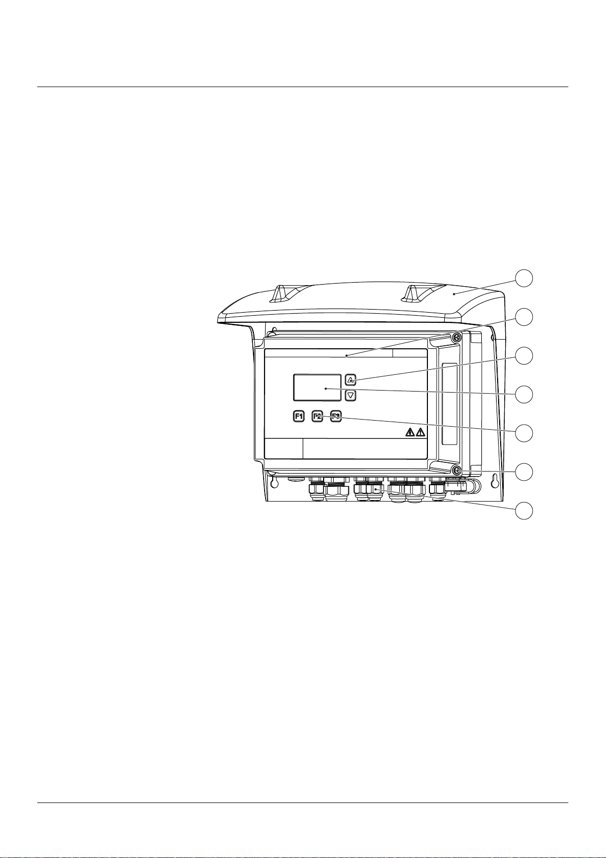
2.5 Communication Platform CPM
The CPM is delivered as a complete unit from BTG, normally in conjunction
with an instrument.
The CPM has the following functions:
• Local display and console for full configuration and operation of the
instrument
• Large illuminated display for easy reading
• Protected from splash and sun
1
3
2
6
4
5
7
Fig 3 CPM overview
1. Protective cover
2. Front cover
3. Scroll keys
4. LCD display with
backlight
5. Function keys
6. Closing screw
7. Cable glands

Product Introduction
12 Product Introduction, CPM - Rev. C © BTG 2021
2.5.1 Technical Data
General
Type
CPM Communication Platform.
Manufacturer
BTG, Säffle, Sweden.
Quality Assurance
Quality-assured in accordance with ISO 9001.
Product Safety
Fulfills all relevant CE-directive requirements, RCM listed, and ETL listed.
Radio Approvals
US, Canada, EU, Japan, Australia, and New Zealand.
Emission / Immunity / Safety
FCC Part 15 Class B
EN 61010-1:2010
EN 61326-1:2013
EN 301489-1 V2.1.1
EN 301489-17 V3.1.1
EN 300328 V2.1.1
EN 300893 V1.8.1
UL 61010-1:2012 Ed.3 +R:29Apr2016
CSA C22.2#61010-1-12:2012 Ed.3+U1;U2
Function Specifications
HCM-8000
Hart communication module using HART® protocol.
Equipped with slot for SD memory card.
Analog output (AO1)
4 - 20 mA. Galvanic isolated. Current limited to min. 3.9 and max. 20.5 mA.
Loop load signal: Voltage supply/load 24 V DC
Active or passive output
Superimposed signal over 4 - 20 mA current loop according to standard HART® protocol.
Analog input (AI1)
4 - 20 mA 250 Ω input resistance
Digital input (DI1 - DI3)
Galvanic isolated
High-ohmic = logical 0
+24 V ≥ 12 mA = logical 1
Digital output (DO)
Galvanic isolated
Maximum 120 mA
Maximum 30 V DC

Product Introduction
© BTG 2021 Product Introduction, CPM - Rev. C 13
FCM-80x0
Fieldbus communication module programmed for PROFIBUS.
Equipped with slot for SD memory card.
Output / Input signal
PROFIBUS (PA)
CCM-8200
Network Interfaces:
Wired Network Connectivity
Ethernet, 10/100 Mbit - RJ45.
Ethernet interface supporting up to 100baseTx.
IEC 11801:2002 CatV compliant M12 type D socket.
The interface supports Auto MDI-X (crossover).
Wireless Network Connectivity
Wi-Fi, Dual-band 802.11 a/b/g/n/ac 1x1
CPM User Interface
Illuminated display. Key pad for adjustment of instrument settings.

Product Introduction
14 Product Introduction, CPM - Rev. C © BTG 2021
Support System Specifications
Supply Voltage
Power supply unit 100 - 240 V AC, 50-60 Hz.
AC input range: 90 - 264 V continuous operation.
Disconnecting Device
An external 2-pole switch close to the CPM is required. The switch must be approved in
accordance with the IEC 60947-2 and IEC 60947-3 requirements.
Power Consumption
100 - 300 VA
Altitude
0 to 2000 m (0-6560ft) without any restrictions.
2000 to 6000 m (6560 to 20000ft) reduce output power or ambient temperature.
Altitude de-rating = 5 W / 1000 m or 5 °C / 1000 m.
Humidity
5 to 95% r.h (IEC 60068-2-30)
Over-voltage Category
Category III: IEC 62103, EN 50178, altitudes up to 2000 m
Category II: altitudes from 2000 m to 6000 m
Degree of Pollution
2: IEC 62103, EN 50178, not conductive
Physical Specifications
Materials
Casing: Polycarbonate thermo plastic
Cable fittings: Polyamide thermo plastic
Storage Temperature
Max. 80 °C (176 °F)
Min. -25 °C (-13 °F)
Operation Temperature
Max. 50 °C (122 °F)
Min. 0 °C (32 °F)
Degree of Protection
IP 65, comparable to NEMA 4x and better, the CPM is intended for use indoors.
Weight
CPM: 2 - 2.5 kg (4.4 - 5.5 lbs) depending on configuration
Cables
Power supply flexible cable: 0.3 - 2.5 mm2 (AWG = 28-12)
Signalling cable: 0.2 - 2.5 mm2 (AWG = 24-12)
Transmitter Cable
Standard length: 10 m [33 ft]
Cable Inlets
There are cable glands for signal cables (diameter 4-8 mm) and for power supply cable
(diameter 4-12 mm) in the bottom of the CPM.
Table of contents
Popular Transmitter manuals by other brands


BWI Eagle
BWI Eagle AIR-EAGLE SR PLUS 36-HH-9 quick start guide

IFM
IFM TA3 Series installation instructions

St. Jude Medical
St. Jude Medical Merlin home EX1100 user manual

SOR
SOR echosonix U71 General instructions

Nice
Nice FLOX1R Installation instructions manual

Creative
Creative BLASTER TRANSMITTER user guide