Volac Ecosyl ECOSYLER 08 User manual

Ecosyler
Applicator
Page
1. Supplied 2
2. Installation
2.1 Tank/Pump 2
2.2 Control box 2
2.3 Nozzle 2
3. Electrical Connections 2
4. Operation 3
4.1 Standby 3
4.2 On 3
4.2.1 Cleaning mode 3
4.2.2 Harvesting mode 4
5. Counter 4
6. Alerts 4
6.1 Low Level 4
6.2 Pump 4
7. Control Box Menu 4
7.1 View the counter reading (Counter? / tonnes or litres) 4
7.2 Reset the counter (ctr clr/CTR=0?) 6
7.3 Application rate (Dos ml/t) 6
7.4 Calibration value (Cal flow) 6
7.5 Configuration of the device (Cfg Dev) 6
8. Maintenance 7
9. Troubleshooting 8
10. Warranty 8
11. Technical data 8
12. Repairs & Spares 8
13. Applicator Parts 9
-1-

1. SUPPLIED
1. 22 litre tank with 3-way valve
2. electronic control box with 8 character LCD display
3. positive displacement peristaltic pump (150 - 7500 ml/h)
4. electronic low level indicator
5. stainless steel nozzle with quick connector
6. 10 metres braided PVC tubing (int. Ø ¼ inch)
7. 7 metre electrical control box/pump connector cable
8. 1.5 metre power connector cable
2. INSTALLATION
2.1 Tank/Pump
Position where it will be easily accessible for filling, draining off excess inoculant and cleaning. For instance it could be
attached to the platform railings or to the side of the harvester behind the driver’s cab. It should not be mounted inside
any of the harvester compartments where elevated temperatures would be detrimental to the survival of the
inoculant bacteria.
2.2 Control Box
Attach to a convenient point inside the harvester cab using the fixing bracket supplied.
2.3 Nozzle
The nozzle should be placed in the lower side of the chute, approximately midway along its length,
eg fit into the centre of a convenient cleaning flap. Drill a 14mm diameter hole in the centre of the
flap and screw the nozzle in place, pointing up the chute once the flap is re-attached.
3. ELECTRICAL CONNECTIONS
1. All connections are via quick connectors (to couple the electrical quick connector, line up the notch inside one end
with the gap in the other end then screw the two parts together tightly using the two dimpled nuts, screwing them in
opposite directions).
2. Connect the pump to the control box using the long connecting cable
3. Connect the control box to the power source
For a harvester with a table sensor - connect the control box directly to the power source according to the wiring
colours shown below.
For a harvester without a table sensor - either cut off the grey wire or attach it to the positive or negative (GND)
terminal.
-2-
Power Source
Positive (+ve) BROWN
Negative (-ve or GND) BLACK
Table Sensor (+ve) GREY
Control
Box Pump

4. OPERATION
4.1 Standby
With the power supply connected the control box is initially in standby mode and the green ‘Power’ LED on the control
box flashes slowly but there is no display and the pump is not functioning.
4.2 On
Switch on by pressing the Power key ( ). The green ‘Power’ LED on the control box illuminates continuously, all
keys are active and the following information appears on the display in sequence: ECOSYLER; version number; estimated
crop harvest rate (t/h).
Note: If you have not wired the control box to a table sensor you must reconfigure your control box to show this
as the control box is supplied assuming a table sensor is attached (see sections 7 and 7.5).
Harvesters with a table sensor: The pump will start automatically when the table is lowered and the harvester begins
harvesting the crop. It will stop when the table is lifted.
Harvesters without a table sensor: The pump is turned on and off manually using the and keys
respectively.
When the pump is operating the green ‘Pumping’ LED on the control box flashes.
All harvesters:
Pressing the key switches the system back to STANDBY.
Pressing the key once (hold down 1 sec) switches to Cleaning mode ‘forward ‘or twice (2 rapid clicks) to Cleaning
mode ‘reverse’.
Pressing the key takes you into the menu where you can reset the counter and change various applicator
parameters (see section 7).
4.2.1 Cleaning mode
Cleaning mode ‘forward’ is selected by holding the key down for 1 second. The display shows ‘Pump >>>’ and the
pump operates at full speed, allowing the tubing to be rapidly filled with inoculant, or water if it is being washed out.
Cleaning mode ‘reverse’ is selected by a rapid double click of the key. The display shows ‘Pump <<<’ and the
pump operates at full speed in reverse, to run any inoculant in the tubes back into the tank.
The cleaning mode can only be selected when the control box is switched on and the pump is not already operating.
If a table sensor is connected, the table should be raised; if there is no sensor, switch off the pump using the key.
The cleaning mode finishes after one minute automatically but can be interrupted by pressing the key once. It
will also stop when the pump is switched on.
TANK FITTINGS CONTROL BOX PUMP
P
-3-
Low Level
Indicator Tube
Holder
Input
To Control
Box To Low
Level
Indicator
Output
Pump
tubing
Centre
hub
Electrical
connection
to pump
3 way valve
Tank
Drain
Tubing
connector
Power On/Off
and LED Not in use
Pumping
Cleaning On/Off
Alert LED
Menu keys
Manual Pump
On/Off keys

4.2.2 Harvesting mode
When the harvester is operating the display usually shows the harvest rate in tonnes/hour (ie the rate at which forage is
being picked up at that point in time) as set by the operator. This can be adjusted during harvest using the dial on the
side of the control box. The pump flow rate adjusts automatically to maintain the additive application rate set on the
control box (see 7.3).
Alternatively, the display can be set to show the rate of additive usage in litres/hour (see 7.5).
At any time during harvest the counter can be viewed (total tonnes harvested or total litres used depending on the
parameter set in the control box configuration – see 7.5) by pressing the key twice. Pressing the key
twice returns you to harvesting mode.
Note: The maximum harvest rate that can be set is limited by the maximum pump flow rate which is 7.6 litres/h. At
20ml/t the maximum harvest rate that can be selected with the dial is 380t/h.
5. COUNTER
The maximum total tonnes that can be recorded is about 32,500 when applying 20ml/t. It calculates litres to the
nearest 10ml up to a maximum of about 650 litres before resetting to zero. The counter is about 90% accurate but this
can be improved by calibrating the pump. At any time in harvesting mode, pressing the key twice allows you to
view total tonnes harvested or total litres used since the counter was last set to zero. Pressing the key twice
returns you to harvesting mode.
Note: The counter cannot be used to monitor total tonnes or total litres continuously on the display.
6. ALERTS
There are two alerts, both of which cause the Alert LED on the control box to flash and an audible warning which can be
cancelled by pressing the key. The display will return to normal but the red LED continues to flash until the fault
is rectified. The control box display identifies the fault.
6.1 Low Level
The low level alert is triggered when the tank is empty - the control box displays ‘No fluid’. There will still be some
inoculant in the system. The 3-way valve assembly retains about 50ml and each metre of tubing 28ml. The alert will
cancel once more inoculant is placed in the tank.
6.2. Pump
The pump alert is triggered if there is no power to the pump or it stops turning - the control box displays ‘Pump err‘. The
pump should be examined to see if there is a blockage, faulty connection, etc. The alert is cancelled either by turning
the pump off manually using the key or by lifting the table, depending on how your control box is configured
(with or without table sensor).
7. CONTROL BOX MENU
The control box menu is used to reset the counters to zero and to set the initial parameters. The menu is on several
levels with more than one parameter per level. The diagram on the next page shows you how to navigate around the
menu.
Note: If the value of any parameter is changed (grey boxes in menu) it must always be confirmed using the
key otherwise the new value will not be registered. You can cancel a setting change with the key as
long as it has not already been confirmed.
7.1 View the Counter Reading (Counter? / tonnes or litres)
While harvesting you can view the counter reading in tonnes/hour or litres/hour (depending on which parameter you
have set in the menu for Configuration of the Device, section 7.5) by pressing the key twice. Press twice to
return to harvesting mode.
P
P
P
P
-4-

-5-
Ecosyler Control Box - Menu Navigation Chart
The and keys move between levels. The and keys move within a level and also increase or decrease the
value of a parameter. To return rapidly to harvesting mode (t/h or l/h) press the once or more.
When values in the red boxes have been changed the must be pressed to confirm the new value, otherwise it will not be
registered. This will also take you to the next parameter in the menu.
t/h or l/h
Counter? Exit ctr clr
CTR=0? DOS ml/t
20 ml/t
cal 1.00 Cfg: 0.00
Cfg: 0.00
Cfg: 0.00
cal flow Cfg Dev Exit Set
Settings Exit
tonnes or
litres
NB. Before returning to
harvest mode you must
confirm all 3 digits, even
if only one changed
t/h or l/h – rate of harvest or additive use
Counter? – accesses the counter
t or l – total tonnes harvested or litres used since counter last reset
ctr clr – accesses the counter
CTR=0? – to reset the counter press
Settings – accesses the parameters that can be changed
Dos ml/t – the rate the additive should be applied to the crop
cal flow – flow rate calibration – default 1.00 for Ecosyl ULV
Cfg Dev – allows a number of parameters to be set. Use the
and keys to switch between 0 and 1 then press
to confirm the new setting
Cfg: 0 0 0 – set at 0 for harvester with table sensor or 1 if none
Cfg: 0 0 0 – display: 0 for t/h; 1 for l/h
Cfg: 0 0 0 – display: 0 for total tonnes harvested; 1 for total litres used

P
P
P
P
P
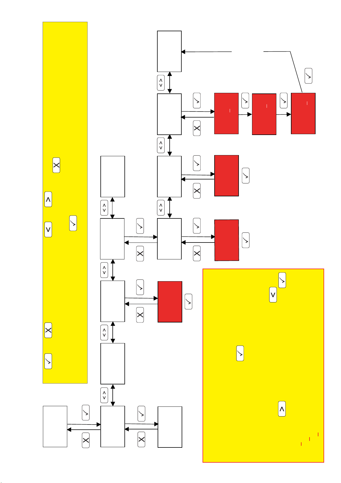
7.2 Reset the Counter (ctr clr/CTR=0?)
To reset the counter to zero, navigate through the menu to ‘ctr clr’ then press the key. The display will indicate
‘CTR = 0?’. Clear the counter by pressing the key again. Return to the harvesting mode by pressing the key
twice.
7.3 Application Rate (Dos ml/t)
This value defines the inoculant application rate on the crop in ml/t. It can be set from 10 ml/t up to 50 ml/t in steps of 1
ml/t. The value is factory preset to 20 ml/t (Ecosyl ULV). The flow rate of the pump in ml/min is determined by this and
the harvest rate set by the dial on the control box.
7.4 Calibration Value (Cal flow)
The pump flow rate is affected by the physical properties of the inoculant, eg viscosity. The Ecosyler is delivered with
the Calibration value set at 1.00 which corresponds to Ecosyl ULV application at 20ml/t. If a different inoculant or flow
rate is used the pump should be recalibrated to retain accuracy. The Calibration value is a multiplication factor of the
flow rate shown on the display (0.85 to 1.15 in steps of 0.01) and aligns the flow rate displayed with the actual flow rate.
Calibrating of the Flow Rate
1. Fill the applicator system with the inoculant to be used
2. Place a measuring jug at the tank outlet to collect the inoculant
3. Configure the pump for use without a table sensor and the display to indicate the flow rate in litres/hour and the
counter in litres, ie in ‘Cfg Dev’ set all three digits to ‘1’. (Note your original settings for reconfiguration later)
4. Reset the counter to zero in ‘ctr clr’
5. Set the calibration value ‘flow rate’ to 1.00, ie ‘cal flow’ = 1.00 (default value for Ecosyl ULV)
6. Set the flow rate to max 7.6 litres/h using the dial on the side of the control box
7. Start the pump by pressing the key on the control box
8. Collect at least 500ml (~4 minutes) then stop the pump by pressing the key
9. View the counter reading in litres
10. Divide the amount of inoculant collected by the counter reading (the counter measures to the nearest 10ml), eg
0.75 in jug ÷ 0.8 on counter = 0.94 (calibration value of inoculant)
11. Enter this new value in ‘cal flow’. Values of 0.85 to 1.15 are allowed. Less viscous inoculants will have values closer to
0.85.
12. Reconfigure the control box to your preferred settings (see point 3 above)
7.5 Configuration of the Device (Cfg Dev)
There are 3 configuration parameters that require setting on the control box before you start harvesting.
The settings are all independent and you can change the display at any point during harvest:
1. Whether the harvester has a table sensor or not
2. Whether the display shows the harvest rate in t/h or the additive usage rate in l/h.
3. Whether the counter shows total tonnes of crop harvested or number of litres of inoculant applied
Note: The control box as supplied is set for a harvester with a table sensor, the display showing harvest rate in
tonnes/hour and the counter total tonnes.
To change the control box settings:
1. Navigate to ‘Cfg Dev’ in the menu then press the key
2. The display indicates ‘Cfg: 0 0 0’ - the cursor underlines the position to change. Use the and keys
to toggle between 0 and 1. To confirm the new setting and move to the next position, press
3. For harvesters with a table sensor, set the first digit to 0; for those without, set it to 1
4. For the display to show the harvest rate in tonnes/h, set the second digit to 0; for it to show the Flow rate in litres/h,
set it to 1
5. For the counter to show total tonnes, set the third digit to 0; for it to show total litres, set the third digit to 1
6. Confirm your final choice using the key
Note: You must confirm all 3 digits before returning to harvest setting, even if you only change one digit. If you
do not, the new value will not be registered
-6-

8. MAINTENANCE
As with any silage inoculant applicator, the tank and tubing should be cleaned at frequent intervals to prevent
microorganisms (inoculant or contaminants) growing inside the tank or tubing. Ideally the whole system
should be washed with clean water between jobs, taking care to clean under the tank rim and flushing the
tubing well. If microbial growth does occur the tank should be scrubbed with hot, soapy water then the whole
system flushed thoroughly with clean water so there is no residual soap.
Draining inoculant from the tank for refrigeration: Use ‘reverse cleaning mode’ to flush any inoculant in the system back
into the tank then drain the tank contents into suitable clean containers, eg original bottles.
Flushing the system: Rinse the inside of the tank thoroughly with clean water and drain off, taking care to clean under
the rim. Close the drain tap and put some more clean water into tank, turn the 3-way valve to the tubing outlet and run
the pump in ‘forward cleaning mode’ to flush the system. You may need more than one cycle. Open the tank drain to
release any water remaining in the tank.
Pump: Regularly check the pump and inside of the pump box are clean and dry.
Out of use: If the pump is not to be used for a prolonged period, remove the rubber tube and holder from inside the pump
to prevent the tube becoming constricted due to prolonged compression at the contact points (see below). Alternatively,
once a week remove the clear pump cover and red disc and manually turn the central hub to a new position.
Removing the tube holder from the pump: Remove the clear cover and the red disc then slide out the orange tube holder.
Turn the centre hub clockwise until it resembles the letter ‘D’. Gently ease the tube out at the left-hand side then rotate
the central hub clockwise to gradually release the rest.
Re-inserting the tube holder into the pump: Turn the centre hub so it resembles the letter ‘D’ then slide in the orange
plastic holder. Press the tube down into place on the left-hand side then gently press the rest of the tube in place while
rotating the hub clockwise. Replace the red disc, taking note of the alignment underneath, and the plastic cover.
Replacing the pump tube: Make sure the tube is not twisted – the two red marks on the tube should both be facing the
same way when attached.
End of season: 1) Wash the whole system thoroughly with clean water; 2) Leave tank drain open during storage;
3) Check the pump and inside of the pump box are clean and dry and remove the pump tube; 4) Check the condition of
the nozzle.
Start of season: 1) Check all tubing for damage; 2) We recommend you fit a new pump tube – a spare is supplied with
the kit; 3) Check the condition of the nozzle and make sure it is correctly positioned in the chute; 4) Run some water
through the system and test the control box and pump are both functioning correctly.
-7-

10. WARRANTY
Provided installation, operation and maintenance is carried out according to the instructions provided with the
applicator, a warranty of 1 year from the date of delivery applies. This covers faulty manufacture only; it does not
cover wear and tear through normal use and is invalidated if any mechanical or chemical damage has occurred to the
parts through misuse or if attempts to repair the unit have resulted in damage. In the case of faulty manufacture,
claims are limited to the repair of the unit and its return to the customer.
11. TECHNICAL DATA
Supply voltage: 12V DC (10.6V DC to 16.4V DC)
Output signal for Ecosyler pump: PWM approx. 80 Hz
Working ambient air temperature: 5 - 50°C
Dimensions tank assembly (WxDxH): 410 x 290 x 590 mm
12. REPAIRS & SPARES
Selmech Supplies
19 Norton Enterprise Park, Whittle Road, Churchfield Industrial Estate, Salisbury, Wilts, SP2 7YS.
9. TROUBLESHOOTING
-8-
Problem Solution
Check connections and for blockages.
Check control box configuration (Cfg Dev) correctly set for +/- table
sensor (1st digit). If table sensor present, table must be down for pump
to work.
Check the tap under the tank is open.
Check for constrictions or breaks in the tubing and blockages (including
in the pump).
Control box power light on but nothing showing on LCD
screen
Try switching the power source off and on again, ie switch harvester
ignition off then on.
Control box not working Is there power to the control box (green LED)? If not, check connections
and fuse (fuse holder on end of control box).
It must be switched ‘ON’ (green LED on continuously).
Try switching it off completely and back on again.
If table sensor present, table must be up.
If no sensor make sure pump is off.
When fill tank and turn on control box, the tank empty alert
comes on
The low level sensor has become stuck as a result of the system not
being flushed with clean water after use. Drain the inoculant from the
tank and wash through with a strong jet of water. If that does not work,
unscrew the LLI and flush through from the other side. This should free
the cylinder that rides up and down the spindle inside the low level
Counter not working properly
Was the reset confirmed before returning to harvesting mode? Reset the
counter to zero again and make sure the tick button is pressed to
confirm.
Pump error alert on control box
Pump working but no inoculant flowing
Power to the control box but buttons not responding
Cleaning mode not working
For more information on ‘Eco’ Applicators contact:

1
2
3 45
6
8
10
9
12
11
16 15 14
24
25
7
13
19
21
22
1718
20
23
ECOSYLER 08 APPLICATOR PARTS
26
Item No.
Description
1
Tank Lid
2
Neck Ring
3
Filter Basket
4
Mounting Bracket
5
Control Box Bracket
6
Control Box
7
Tank
8
Pump Housing Cover
9
Pump Housing
10
Pump
11
6mm Hose Tail
12
Quick Connector A
13
Quick Connector B
14
Nozzle
Item No.
Description
15
Quick Connector A
16
Quick Connector B
17
10mm Hose Tail
18
Reducing Bush
19
3 Way Valve
20
Tank Drain
21
Retaining Clip
22
Low Level Indicator
23
Braided Hose
24
Power Connecting Cable
25
Pump-Control Box Cable
26
Pump Tubing
-9-
00024_Ecosyler Guide_v2 0915
Table of contents
Other Volac Farm Equipment manuals