Vollrath Stoelting Flavor Burst STL-80SS-DLX User manual

A VOLLRATH® DIVISION
Flavor Burst® Soft Serve System
Striped Deluxe
Operator’s Manual
Manual No. 513843


©2022 Flavor Burst Company Printed in February Printed in
All Rights Reserved The United States of America
Flavor Burst ® Stoelting® Ready
8-Flavor Deluxe Soft Serve
“Stripe” System
Model STL-80SS-DLX
Equipment, Maintenance and
Operations Manual
For questions, support, and ordering
parts, contact Stoelting Company’s
White Glove Service.
Phone: 1-800-319-9549
Warranty & Installation Form
An installation form is provided with every STL-80SS-DLX system, located inside the unit with this
manual. It is important that the operator / installer completely fill out the installation documents
accompanying the unit before using this system. Any questions or concerns regarding the warranty
should be clarified upon delivery or installation. For warranty details please refer to Stoelting’s website
www.stoeltingfoodservice.com.

1
TABLE OF CONTENTS
FCC Conformity Statement..…...………………………………………….………………...3
Introduction……………………………...………………………………………….………….4
Safety Precautions……………………………..…………….………..……..….…………....4
Environmental Notices………………...………………………………………….………….6
Parts Identification/Function……...……………………….……..…..……….……..….…..7
Daily Opening Procedures……..………………………….…….…..…….………..……...24
Sanitizing the Injector System……………………………….………………..…...…24
Assembling the Injector Assembly………………...……………………………...…25
Installing the Injector System………………………………….………………...…...26
Other items to check during opening procedures……………………………….…27
Daily Closing Procedures………………………………………….……………….…….…28
Removing the Injector System…………………………………...……………...…...28
Disassembling the Injector Assembly………………………………………….…….29
Sanitizing the Injector System…………………………………....……………...…...30
Replacing the Syrup Flavors…………...…………………………..…….………...……...32
Scheduled Maintenance…………...……………………………….…….………...…...….36
Clean-In-Place (CIP) Procedure…………………………………....……….…..…...36
CIP – Phase 1: Prep………………………...……………………………...…36
CIP – Phase 2: Flush……………………………….....……………….......…38
CIP – Phase 3: Clean………………………………………….……….......…39
CIP – Phase 4: Reassemble………………………………….……….......…40
Filling the Sanitizer Tank……………………………………..........……………....…41
Priming the Syrup System………………………………….....…………...….......…42
Replacing Injector Head O-Rings………………………………….....…………...…43
Miscellaneous Cleaning Procedures………………………………………….......…44
Cleaning the Injector Assembly Suspension Bracket….....……………...…44
Area Under the Cabinet………………………………….....……………....…45
Inside the Cabinet………………………………….....………………….....…46
Tube / Cable Casing Assemblies………………………….…….…….…..…46
9-Tube Assembly Syrup Lines……………………....……………….…....…46
Touch Panel and Mounting Bracket……………....……………….……...…47
Winterizing the Unit ………………………………..…………...……………..…...…47

2
TABLE OF CONTENTS (continued)
Equipment Setup……………………………………………………...…..……….……..….50
Installing the Touch Panel and Mounting Bracket………………………...….....…50
Draw Switch Options……………………………………….………...……..……...…53
Installing the Draw Switch Extension…………….………………..……...…53
Installing the Draw Handle Switch…………………….……...…………...…53
Sanitizing the Injector System………………………………………...…………...…54
Assembling the Injector Assembly…………………………………....……...…...…54
Installing the Spout Adapter…………………………………..…………………...…55
Installing the Injector System and Suspension Bracket………………………...…55
Mounting the Tube / Cable Casing Assemblies……………………...……….....…58
Connecting the Unit Syrup Line and Pump Harness Cable..…………….......…60
Installing the Electronics Box and Power Connections..…………….......…...........61
Filling the Sanitizer Tank………………………….……………............................…64
Installing Flavors and Priming Syrup Lines………………………...………..…...…64
Color Touch Panel Overview.…….………………..…………………………....……....…68
Quick Reference Guide for Color Touch Panel Setup..…..……...…………….….68
Testing the STL-80SS-DLX System………..…….……......……………...…......…69
Directory of Cleaning Procedures……………………………...………………..…….….72
Parts Replacement Schedule………...………………….………………..….…………….73
Recommended Maintenance Items Replacement Schedule………………....…....…74
Alternate Parts and Kits by Freezer Model……………………………...……...…....….74
Ordering/Service Information…………….…….…...…………………..……….........…..75

3
FCC Conformity Statement:
This device complies with Part 15 of the FCC Rules. Operation is subject to the following two
conditions: (1) this device may not cause harmful interference, and (2) this device must accept any
interference received, including interference that may cause undesired operation.
Changes or modifications not expressly approved by the party responsible for compliance could void
the user's authority to operate the equipment.
NOTE: This equipment has been tested and found to comply with the limits for a Class B digital device,
pursuant to Part 15 of the FCC Rules. These limits are designed to provide reasonable protection
against harmful interference in a residential installation. This equipment generates, uses and can
radiate radio frequency energy and, if not installed and used in accordance with the instructions, may
cause harmful interference to radio communications. However, there is no guarantee that interference
will not occur in a particular installation. If this equipment does cause harmful interference to radio or
television reception, which can be determined by turning the equipment off and on, the user is
encouraged to try to correct the interference by one or more of the following measures:
-- Reorient or relocate the receiving antenna.
-- Increase the separation between the equipment and receiver.
-- Connect the equipment into an outlet on a circuit different from that to which the receiver is
connected.
-- Consult the dealer or an experienced radio/TV technician for help.
FCC RF Radiation Exposure and SAR Statements SAR Statement.
The Flavor 10* has been tested for body-worn Specific Absorption Rate (SAR) compliance. The FCC
has established detailed SAR requirements and has established that these requirements. RF Exposure
Information. The radio module has been evaluated under FCC Bulletin OET 65C (01-01) and found to
be compliant to the requirements as set forth in CFR 47 Sections, 2.1093, and 15.247 (b) (4)
addressing RF Exposure from radio frequency devices. This model meets the applicable government
requirements for exposure to radio frequency waves. The highest SAR level measured for this device
was 0.293W/kg.
*The Flavor 10 is also referred to as the Touch Panel throughout this manual.

4
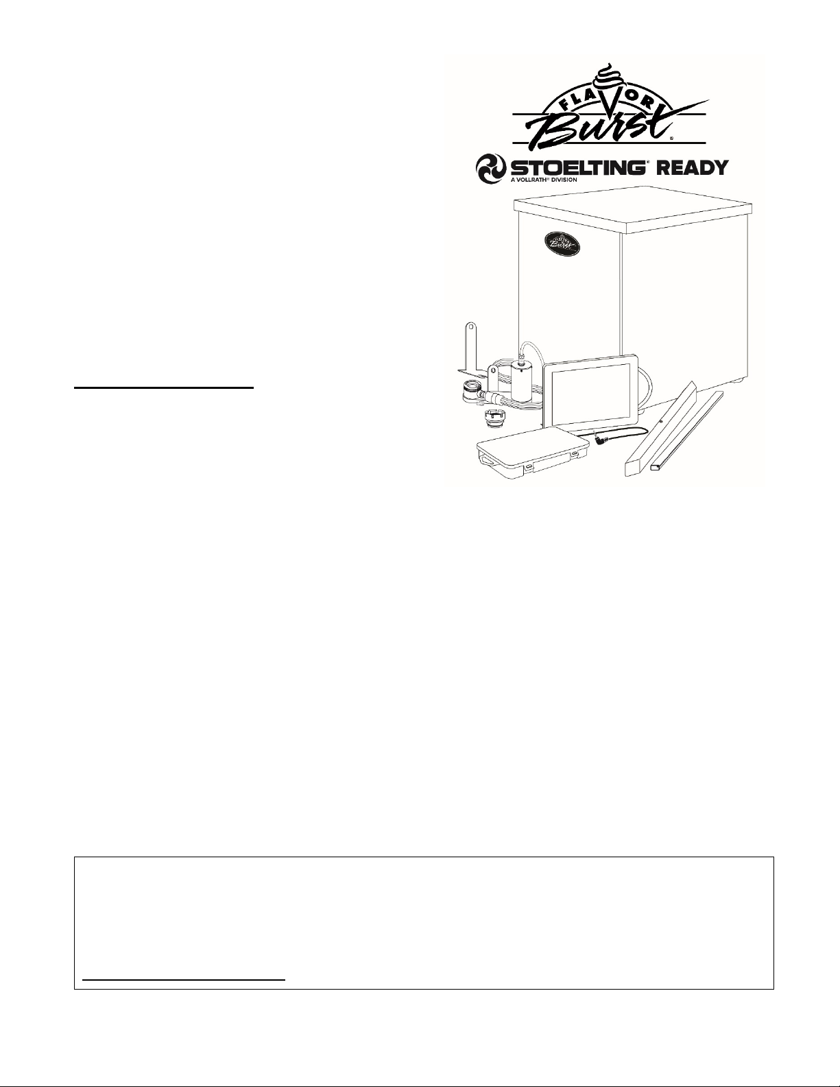
Congratulations on your purchase of the Flavor
Burst Stoelting-Ready flavoring system. As a
food and beverage provider, your customers
are your greatest asset. Your primary concern
must be the health and welfare of your
customers. This manual provides everyday
operating guidelines and procedures. Special
functions have been incorporated into the
equipment to provide simple and effective
cleaning and sanitizing of your unit. We urge
you to follow these instructions carefully and
maintain strict sanitary practices in your daily
operating routine.
The Flavor Burst system is added to a soft
serve freezer to inject concentrated flavorings
throughout soft serve product as it is dispensed.
Dispensing Flavor Burst product is very simple.
Select a flavor from the Touch Panel and draw
the product. The Flavor Burst system will
automatically flavor the product at the spout.
You can also have multiple flavors per serving.
Simply select the flavors from the Touch Panel
and draw the product. The system will switch
from one flavor to the next in a smooth,
continuous motion, layering the serving with
different, delicious flavors. The STL-80SS-
DLX model has a deluxe cabinet, which
includes and internal sanitizer tank and
integrated door.
Flavor Burst®syrup is stored within the
equipment cabinet in 1-gallon disposable bags.
Proper syrup injection rate is maintained by
adjusting the flavor level on the system Touch
Panel.
Components of the STL-80SS-DLX system
should be cleaned daily to ensure the highest
standard of sanitation. When your equipment is
delivered or if it has been unused for more than
24 hours, follow the DAILY OPENING
PROCEDURES.
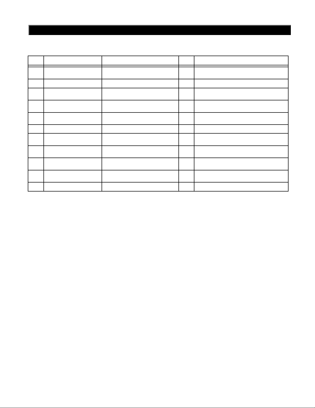
NOTE: PARTS AND PART NUMBERS MAY
VARY FROM WHAT IS SHOWN AND LISTED.
CONTACT STOELTING COMPANY’S WHITE
GLOVE SERVICE IF YOU HAVE ANY
QUESTIONS. Phone 800-319-9549
Always follow these safety precautions when
operating the Flavor Burst®system:
DO NOT operate the system without
reading this operator’s manual. Failure to follow
this instruction may result in equipment
damage, poor system performance, health
hazards, or personal injury.
DO NOT operate the system unless it is
properly grounded. Failure to follow this
instruction may result in electrocution.
DO NOT operate the system with larger
fuses than specified on the system data label.
Failure to follow this instruction may result in
electrocution or damage to the machine.
Consult your electrician.
DO NOT put objects or fingers in the
door spout. Failure to follow this instruction may
result in contaminated product or personal
injury from blade contact.
The STL-80SS-DLX cabinet system must
be placed on a level surface capable of
supporting at least 220 lbs of weight. Failure to
comply may result in personal injury or
equipment damage.
DO NOT place more than 25 lbs of
weight on top of the cabinet. Failure to comply
may result in personal injury or equipment
damage.
DO NOT install the unit in an area where
a water jet could be used, and do not use a
water jet to clean or rinse the system. Failure to
follow these instructions may result in serious
electrical shock.
INTRODUCTION SAFETY PRECAUTIONS

5
HAZARD COMMUNICATION STANDARD
(HCS) – The procedure(s) in this manual
include the use of chemical products. These
chemical products will be highlighted in
bold-faced letters followed by the
abbreviation (HCS) in the text portion of the
procedure. See the Hazard Communication
Standard (HCS) manual for the appropriate
Material Safety Data Sheet(s) (MSDS).
NOISE LEVEL: Airborne noise emission
does not exceed 70 dB(A) when measured at a
distance of 1.0 meter from the surface of the
machine and at a height of 1.6 meters from the
floor.
NOTE: Operations Manual subject to
change. Contact White Glove Service for most
recent updates concerning the STL-80SS-DLX
unit.
NOTE: Access to the service area is
restricted to persons having safety / hygiene
knowledge and practical experience of the
appliance.
NOTE: This appliance can be used by
children aged from 8 years and above and
persons with reduced physical, sensory, or
mental capabilities or lack of experience and
knowledge if they have been given supervision
or instruction concerning use of the appliance in
a safe way and understand the hazards
involved.
NOTE: Children shall not play with the
appliance.
NOTE: Cleaning and user maintenance
shall not be made by children without
supervision.
ENVIRONMENTAL NOTICES
If the crossed out wheeled bin symbol is affixed to this product, it signifies that this product
is compliant with the EU Directive for Waste Electric/Electronic Goods (WEEE) as well as
other similar legislation in affect after August 13, 2005. Therefore, it must be collected
separately after is use is completed, and cannot be disposed of as unsorted municipal
waste.
The user is responsible for returning the product to the appropriate collection facility, as specified by your
local codes. For additional information regarding applicable local laws, please contact the municipal
facility and/or local distributor.

6
PAGE INTENTIONALLY LEFT BLANK

7
General System Overview (See Figure 1)
ITEM PART NO. DESCRIPTION QTY. FUNCTION
1 STOEELE906A TOUCH PANEL ASSEMBLY WITH
BRACKET 1 Flavor Burst unit command center.
2 STOEINJ424STL-SS FLAVOR BURST ASSEMBLY 1 Injects syrups into the product.
3 STOEMIS3026S TOUCH PANEL CABLE CASING 1 Conceals and protects the Touch Panel
cable, as well as attaches it to the freezer.
4 STOEMIS3196 STAINLESS TUBE / CABLE
CASING ASSEMBLY 1 Attaches the flavor lines and/or cables to the
side of the freezer.
5 STOEELE525M MALE TO MALE 48” SWITCH
EXTENSION 1 Connects Touch Panel to the freezer switch.
6 STOECAB113 FLAVOR TRAY 8 Houses syrup bags.
7 N/A FLAVOR BURST SOFT SERVE
DELUXE CABINET 8-FLAVOR 1 Houses 8 syrup trays and bags.
8 STOESYR944 SYRUP BAG CONNECTOR
ASSEMBLY 8 Transports syrup from the bag to the pumps.
9 N/A DELUXE ELECTRONICS BOX 1 Houses the electronics board and
connections.
10 STOESPR5800STL-SS SPARE PARTS KIT – SOFT
SERVE 1 Houses extra spare parts and wear items.
11 STOEELE434 POWER CABLE 1 Supplies the electronics board with power.
PARTS IDENTIFICATION/FUNCTIONS

8
General System Overview
Figure 1

9
Outer Cabinet (See Figure 2)
ITEM PART NO. DESCRIPTION QTY. FUNCTION
1 STOECAB237 CABINET TOP PANEL 1 Covers the top of the inner cabinet.
2 STOECAB235L
CABINET LEFT SIDE PANEL 1 Covers the left side of inner cabinet.
3 N/A INNER CABINET ASSEMBLY 1 Houses syrup trays and bags.
4 STOECAB239 CABINET FRONT DOOR PANEL 1 Front door, allows access to flavor bags.
5 STOECAB256 FRONT DOOR HANDLE 1 Allows grip for opening front panel.
6 STOEFAS2014
8-32 X 1/2 PAN HEAD SCREW 2 Fastens the handle to front door panel.
7 STOERUB618 RUBBER BUMPER W/ WASHER 4 Provides spacing between cabinet base and
table.
8 STOEFAS2064
10-32 X 1/2" PAN HEAD SCREW 4 Fastens rubber bumpers to cabinet base.
9 STOEMIS3074
DUST CAP 4 Covers screw hole in rubber bumper.
10 STOECAB236TS
CABINET REAR PANEL 1 Allows access to pumps.
11 STOECAB235R
CABINET RIGHT SIDE PANEL 1 Covers right side of inner cabinet.
12 STOEMIS3150 FLAVOR BURST LOGO DECAL 1 Displays Flavor Burst trademark logo.
13 STOEFAS2024 8-32 X 1/4 PAN HEAD SCREW 2 Secures back panel to base.

10
Outer Cabinet (Continued)
Figure 2

11
Inner Cabinet (See Figure 3)
ITEM PART NO. DESCRIPTION QTY. FUNCTION
1 STOECAB201 SYRUP RACK COVER PANEL 1 Keeps side and inner panels stable.
2 STOECAB204L SYRUP RACK LEFT PANEL 2 Holds outer syrup rails.
3 STOESYR945 SYRUP BAG CONNECTOR
ASSEMBLY – SOFT SERVE 8 Transports syrup from the bag to pumps.
4 STOECAB245 SYRUP TRAY RAIL 16 Holds flavor trays in place.
5 STOECAB145 TRAY SUPPORT BRACKET 8 Houses flavor line leading to syrup bag.
6 STOECAB203 SYRUP RACK DIVIDER PANEL 2 Holds inner syrup rails.
7 STOECAB202 SYRUP RACK BACK PANEL 1 Attaches the inner and side panels.
8 STOEMIS3028-80M
SANITIZER FLUSH TUBE
ASSEMBLY – SOFT SERVE INT 1 Flushes flavor lines with sanitizer when
attached.
9 STOECAB233 SYRUP RACK BASE PANEL 1 Attaches the bottom of the inner and side
panels.
10 STOECAB204R SYRUP RACK RIGHT PANEL 1 Holds outer syrup rails.
11 STOEFAS2024 8-32 X 1/4" PAN HEAD SCREWS 48 Fastens pump brackets and pumps and
other cabinet parts.
12 STOECAB205A ACCESSORY MOUNTING
BRACKET-A 1 Secures Accessory Mounting Bracket to
cabinet base.
13 STOECAB205CTP ACCESSORY MOUNTING
BRACKET
–
CTP DLX 1 Secures pump cable to cabinet base.
14 STOEMIS3192 LOCKING HOLE PULUG 1 Closes up the extra opening in the mounting
plate.
15 STOEMIS3217 OPEN-CLOSE BUSHING 5/8” 1 Protects the pump harness cable.
16 STOEELE932DLX PUMP & SANITIZER CABLE
HARNESS
–
CTP DLX 1 Provides power to the syrup and sanitizer
pumps.
17 STOESAN748 PERISTALTIC SANITIZER PUMP 1 Pumps sanitizer solution to flush tube and
sanitizer line.
18 STOESYR307 PERISTALTIC SYRUP PUMP –
SOFT SERVE 8 Pumps syrup from flavor bags into flavor
lines.
19 STOECAB255 PUMP BRACKET 3 Holds pumps.
20 STOESYR927 INTERNAL 9-TUBE ASSEMBLY 1 Transports syrup from bags to the 9-Tube
Assembly.

12
Inner Cabinet (Continued)
Figure 3

13
Injector Assembly and Related Parts (See Figure 4)
ITEM PART NO. DESCRIPTION QTY. FUNCTION
1 STOEINJ424STL-SS
INJECTOR ASSEMBLY WITH
SYRUP LINES, ADAPTER, &
BRACKET
1 Transports and injects syrup into product.
2 STOEINJ422 INJECTOR HEAD ASSEMBLY 1 Connects flavor line to inject syrups into product.
2A STOERUB652-RSS SMALLER SYRUP PORT O-
RING 1 ea. Provides sealed cavity inside syrup port.
2B STOERUB651 INJECTOR HEAD O-RING 2-020 1 ea. Provides a sealed cavity.
2C STOERUB660 LARGER SYRUP PORT O-RING 1 ea. Provides sealed cavity inside syrup port.
3 STOEINJ321 GEAR CARTRIDGE ASSEMBLY 1 Rotates product for even syrup distribution.
4 STOESYR932 6' 9-TUBE ASSEMBLY 1 Supplies syrup to Injector Head from pumps.
4A STOEFAS2051 ROLLED FLANGE EYELET 18 ea Provides tension in syrup line to affix to line
coupler.
4B STOEROT510 LINE COUPLER 2 ea. Holds flavor lines in place.
4C STOEROT515C 9-TUBE ASSEMBLY WAVE
SPRING 1 ea. Provides tension between tube connectors.
4D STOEINJ116 LINE COUPLER NUT - BLACK 1 ea. Attaches flavor tubes to flavor manifold.
4E STOESYR901 6' 9-TUBE ASSEMBLY TUBES 9 ea. Brings syrup from pump to Injector Head.
4F STOEROT511 LINE COUPLER NUT 1 ea. Connects flavor lines to the internal 9-Tube
Assembly.
4G STOERUB602 9-POS TUBE CONN. GASKET 1 ea. Provides sealed cavity.
5 STOEINJ117 TUBE CONNECTOR BODY –
BLACK 1 Secures flavor line manifold to flavor lines.
6 STOEMIS3142 FLAVOR LINE DUST CAP – FB
80 1 Covers syrup manifold when not connected.
7 STOEINJ201A SYRUP MANIFOLD - BLACK 1 Connects flavor line to Injector Head.
8 STOERUB601 9-POS DUCKBILL CHECK
VALVE 1 Provides sealed cavity and prevents syrup
leakage.
9 STOEMIS3226
INJECTOR ASSEMBLY
SUSPENSION BRACKET – 4
POST DOOR
1 Supports the Injector Assembly against the
freezer door and keeps it level.
10 STOEINJ330TS INJECTOR MOTOR ASSEMBLY 1 Supplies power to Motor which turns gears.
11 STOEINJ331 INJECTOR GEAR BOX
ASSEMBLY 1 Gears turn Gear Cartridge for even syrup
distribution.
11A STOEFAS2023 ACCESSORY MOUNTING
BRACKET KNOB 1 ea. Secures base mounting bracket to Gear Box.
12 STOEADPT500FBA
SPOUT ADAPTER W/ O-RINGS 1 Attaches Injector Assembly to freezer door.
12A STOERUB653 SPOUT ADAPTER O-RING 1 ea. Creates tension to secure adapter to freezer door.
12B STOEADPT500FB SPOUT ADAPTER BODY 1 ea. Attaches Injector Assembly to freezer.
12C STOERUB632 SPOUT ADAPTER O-RING 1 ea. Creates tension to secure adapter to Injector
Head.
13 STOEMIS3225
INJECTOR ASSEMBLY
SUSPENSION BRACKET – 2
POST DOOR
1 Supports the Injector Assembly against the
freezer door and keeps it level.

14
Injector Assembly and Related Parts (Continued)
ITEM PART NO. DESCRIPTION QTY. FUNCTION
14 STOEMIS3196
STAINLESS 9-TUBE CASING
ASSEMBLY 1 Protects and holds the cables and 9-Tube
Assembly in place on the freezer side panel.
14A STOEMIS3190 STAINLESS 9-TUBE CASING
HINGED CHANNEL 1 ea. Covers and protects the cables and tubes of the
Casing Assembly.
14B STOEMIS3051 CH-6 CHANNEL MAGNET
ASSEMBLY 2 ea. Holds the Casing Channel to freezer panel.
14C STOEFAS2040 6-32 x 1/4 PAN HEAD SCREW 1 ea. Secures Casing cover to mounting brackets.
14D STOEFAS2024 8-32 x 1/4 PAN HEAD SCREW 4 ea. Secures the magnet assembly to the mounting
brackets.
14E STOEFAS2035 8-32 NUT – EXT. LOCK WASHER 4 ea. Secures the magnet assembly to the mounting
brackets.
Figure 4

15
Syrup Pump and Related Parts (See Figure 5)
ITEM PART NO. DESCRIPTION QTY. FUNCTION
1 N/A SOFT SERVE SYRUP PUMP
ASSEMBLY 8 Pumps syrup from flavor bags to flavor lines.
1A STOESYR307 PERISTALTIC SYRUP PUMP 1 ea. Pumps syrup from flavor bags to flavor lines.
1B STOETUB806 1/8” SYRUP PUMP REPL TUBE 1 ea. Transports syrup through pump.
1C STOEFAS2067 SYRUP PUMP TUBE WASHER-1/4 1 ea. Secures pump tube.
1D STOEFAS2066 SYRUP PUMP CLAMP-HOSE-1/4" 1 ea. Prevents pump tube from slipping.
1E STOEFAS2051
ROLLED FLANGE EYELET 1 ea. Creates tension for tighter fit.
1F STOEFIX1036 1/4" TO 1/4" OD UNION ELBOW 1 ea. Connects syrup in tube to pump.
1G STOEFIX1035 1/4 TO 3/16 OD REDUCING UNION 1 ea. Connects syrup pump to flavor line out.
2 STOESYR944 SYRUP TUBE ASSEMBLY –
SOFT SERVE 8 Transports flavor from bag to pump.
2A STOEFIX1054 1/4” ID HOSE BARB SHUTOFF 1 ea. Connects flavor line to flavor bag.
2B STOESYR902 FLAVOR-IN TUBE 1 ea. Carries syrup from syrup bag to pump.
2C STOETUB811 TUBE-SILICONE .188X.375 PE
FB80 1 ea. Connects barb fitment to tube port.
2D STOEFIX1048 FITTING-1/4X1/4 BARB FB80 1 ea. Connects syrup tube to silicone tube.
3 STOESYR927 INTERNAL 9-TUBE ASSEMBLY 1 Transports syrup from bags to flavor 9-Tube
Assembly.
3A STOESYR900 4' 9-TUBE ASSEMBLY TUBE 9 ea. Brings syrup from pump to Injector Head.
3B STOEROT511 LINE COUPLER NUT 1 ea. Connects flavor lines to the internal
9-Tube Assembly.
3C STOEROT512 TUBE CONNECTOR BODY 1 ea. Connects internal 9-Tube Assembly to
flavor lines.
3D STOEROT510 LINE COUPLER 1 ea. Holds flavor lines in place.
3E STOEFAS2051
ROLLED FLANGE EYELET 9 ea. Secures flavor lines to line coupler.
3F STOEMIS3023 FLAVOR LINE DUST CAP 1 ea. Cover to protect end of flavor lines.
4 STOECAB113 FLAVORING TRAY 8 Houses syrup bags.
5 STOEELE932 PUMP & SANITIZER CABLE
HARNESS 1 Provides power to the syrup and sanitizer
pumps.

16
Syrup Pump and Related Parts
Figure 5

17
Sanitizer Pump and Related Parts (See Figure 6)
ITEM PART NO. DESCRIPTION QTY. FUNCTION
1 STOEMIS3028-80M
FLUSH TUBE ASSEMBLY 1 Connects with flavor line to flush with
sanitizer solution.
1A STOEFIX1051 1/4” ID HOSE BARB ELBOW 2 ea. Connects to the syrup line and sanitizer tank to
transport sanitizer solution.
1B STOESYR931 CLEAR TUBING 3 ea. Transports sanitizer to Pump Flush Adapter
fitments and to the sanitizer tank.
1C STOEFIX1046 FLUSH TUBE “Y” CONNECTOR 1 ea. Splits sanitizer flush tube into two tubes.
2 STOETUB807 SANITIZER TUBE REPLACEMENT 1 Transports sanitizer through pump.
3 STOESAN748 SANITIZER PUMP ASSEMBLY 1 Supplies sanitizer to flush tube.
4 STOEELE932DLX PUMP & SANITIZER CABLE
HARNESS - DELUXE 1 Provides power to the syrup and sanitizer
pumps.
5 STOEFIX1035 1/4 TO 3/16 OD REDUCING UNION 1 Connects elbow to sanitizer line.
6 STOEFIX1045 1/4" TUBE TO 1/4" HOSE STEM 3 Creates tension for tighter fit.
7 STOEFIX1036 1/4" TO 1/4" OD UNION ELBOW 1 Connects syrup in tube to pump.
8 STOESAN756 SANITIZER TANK ASSEMBLY 1 Houses sanitizer cleaning solution.
8A STOESAN749 THREADED CHECK VALVE 1 ea. Allows air to fill Sanitizer Tank.
8B STOESAN750 SANITIZER TANK DOME NUT 1 ea. Mounts check valve to Sanitizer Tank.
8C STOEFIX1052 SANITIZER TANK QUICK
CONNECT 1 ea. Connects sanitizer lines to Sanitizer Tank.
8D STOESAN755 SANITIZER TANK CAP 1 ea. Allows Sanitizer Tank to be refilled.
8E STOESAN754 SANITIZER CAP O-RING 1 ea. Seals the Sanitizer Tank opening to
prevent leakage.
8F STOESYR931 CLEAR TUBING 1 ea. Transports sanitizer to flush tubes.
8G STOESAN752 SANITIZER TANK 1 ea. Houses sanitizer cleaning solution.
8H STOERUB604 SANITIZER TAINK O-RING 4 ea. Seals sanitizer tank’s quick connect & check
valve openings.
9 STOESYR927 INTERNAL 9-TUBE ASSEMBLY 1 Transports syrup from bags to flavor 9-Tube
Assembly.
9A STOESYR900 4' 9-TUBE ASSEMBLY TUBE 5 Brings syrup from pump to Injector Head.
9B STOEROT511 LINE COUPLER NUT 1 Connects flavor lines to the internal
9-Tube Assembly.
9C STOEROT512 TUBE CONNECTOR BODY 1 Connects internal 9-Tube Assembly to
flavor lines.
9D STOEROT510 LINE COUPLER 1 Holds flavor lines in place.
9E STOEFAS2051 ROLLED FLANGE EYELET 9 Secures flavor lines to line coupler.
9F STOEMIS3023 FLAVOR LINE DUST CAP 1 Cover to protect end of flavor lines.
Table of contents
Other Vollrath Ice Cream Maker manuals

Vollrath
Vollrath Stoelting F212 User manual

Vollrath
Vollrath Stoelting CBB Series User manual

Vollrath
Vollrath STOELTING SF144 User manual

Vollrath
Vollrath STOELTING CC101W User manual

Vollrath
Vollrath Stoelting U411 User manual

Vollrath
Vollrath Stoelting E131-OT2 User manual

Vollrath
Vollrath Stoelting U421 I2 User manual

Vollrath
Vollrath Stoelting CC303W User manual

Vollrath
Vollrath STOELTING Flavor Burst STL-40SS-JR User manual

Vollrath
Vollrath STOELTING O431 I2 User manual