manuals.online logo
Brands
  1. Home
  2. •
  3. Brands
  4. •
  5. Voltronic Power
  6. •
  7. Inverter
  8. •
  9. Voltronic Power 1KVA User manual

Voltronic Power 1KVA User manual

Inverter
1KVA/2KVA
V. 1.6
1. Introduction
Thank you for purchasing the inverter. This simple solar inverter is designed to power your
home appliances or precious 3C electronics. It also can handle motor-type loads with high
surge power such as vacuums, small freezers, or drills. If the inverter is equipped with solar
charger, it becomes solar inverter which can convert solar power to battery power and provide
continuous power to connected equipment during night time.
2. Product Overview
Front View
Back View
Quick Guide
LCD display (Please see the Operation section for
the details of LCD display.
Power switch
1. Output receptacles (4xschuko,
4xuniversal, 6xNEMA, 4xIndia or 4x
South Africa)
2. AC input
3. Circuit breaker
4. External battery connectors
5. Charge current selector: 10 A or 20
A
6. Operation mode selector: UPS or
Inverter
7. Solar panel terminal (option)
8. Solar charging indicator (option)
9. Charger fault indicator (option)
3. Important Safety Warning (SAVE THESE INSTRUCTIONS)
Before using the inverter, please read all instructions and cautionary markings
on the unit, this manual and the batteries.
General Precaution-
Install the UPS in a protected area that is free of excessive dust and has adequate air flow.
Please place the UPS away from other units at least 20 cm to avoid interference. Do NOT
operate the UPS where the temperature and humidity is outside the specific limits. (Please
check the specs for the limitations.)
CAUTION! The unit is designed for indoor use. Do not expose this unit to rain, snow or
liquids of any type.
CAUTION! To reduce risk of injury, only use qualified batteries from qualified distributors or
manufacturers. Any unqualified batteries may cause damage and injury. Do NOT use old or
overdue batteries. Please check the battery type and date code before installation to avoid
damage and injury.
WARNING! It's very important for system safety and efficient operation to use appropriate
external battery cable. To reduce risk of injury, external battery cables should be UL certified
and rated for 75°C or higher. And do not use copper cables less than 10AWG. Below is the
external battery cable reference according to system requirements.
Table 1 Minimum Recommended Battery Cable Size versus Length
Model
Typical Amp.
1 meter (one-way)
Dia-mm
1K/2K
59 A
AWG 8
5.9
CAUTION! Do not disassemble the inverter. Contact with the qualified service center when
service or repair is required.
WARNING! Provide ventilation to outdoors from the battery compartment. The battery
enclosure should be designed to prevent accumulation and concentration of hydrogen gas at
the top of the compartment.
CAUTION! Use insulated tools to reduce the chance of short-circuit when installing or working
with the inverter, the batteries, or other equipments attached to this unit.
CAUTION! For battery installation and maintenance, read the battery manufacturer's
installation and maintenance instructions prior to operating.
Personnel Precaution -
CAUTION! Careful to reduce the risk or dropping a metal tool on the batteries. It could spark
or short circuit the batteries and could cause an explosion.
CAUTION! Remove personal metal items such as rings, bracelets, necklaces, and watches
when working with batteries. Batteries can produce a short circuit current high enough to
make metal melt, and could cause severe burns.
CAUTION! Avoid touching eyes while working near batteries.
CAUTION! Have plenty of fresh water and soap nearby in case battery acid contacts skin,
clothing, or eyes.
CAUTION! NEVER smoke or allow a spark or flame in vicinity of a battery.
CAUTION! If a remote or automatic generator start system is used, disable the automatic
starting circuit or disconnect the generator to prevent accident during servicing.
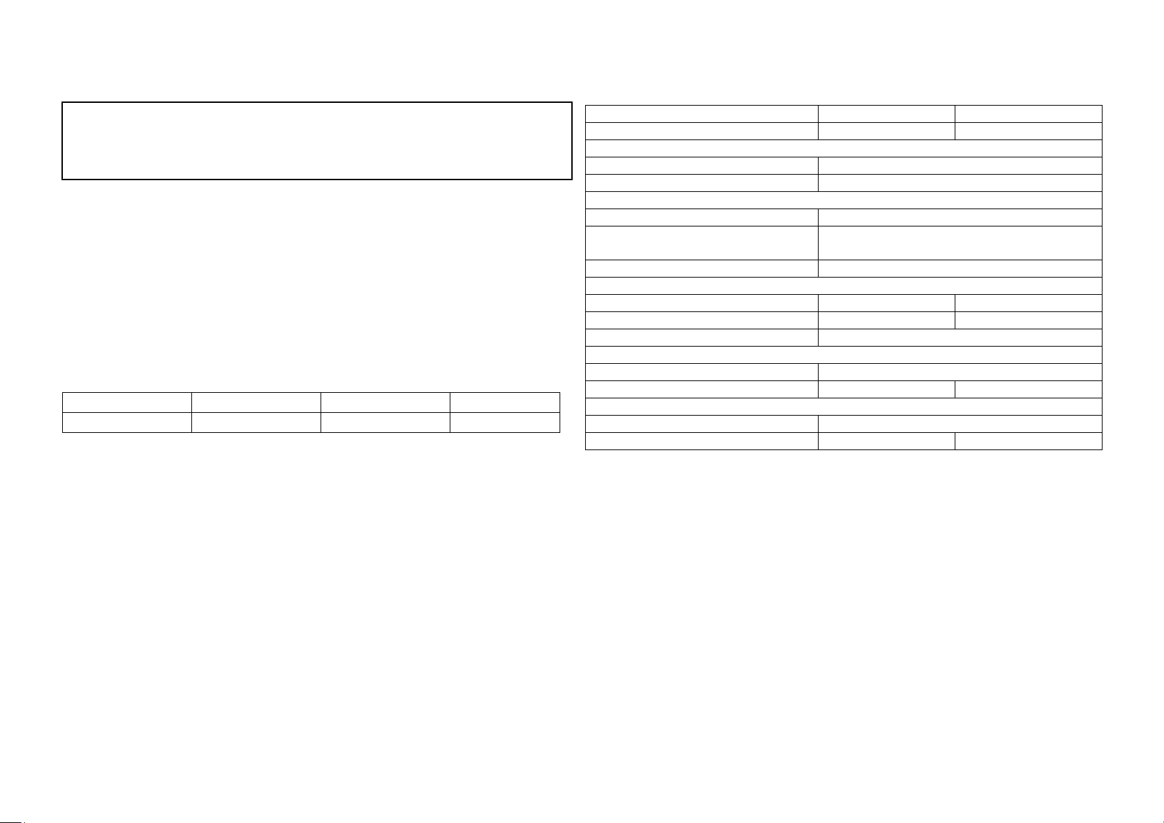
4. Specifications
MODEL
1K
2K
CAPACITY
1000VA/600 W
2000VA/1200 W
INPUT
Voltage
110/120 VAC or 220/230 VAC
Voltage Range
75-150 VAC or 140-300 VAC
OUTPUT
Voltage Regulation (Batt. Mode)
+/-10%
Transfer Time
Typical 4-8 ms, 13ms max. (For PC)
40 ms max. (For Home Appliances)
Waveform
Pure Sine Wave
BATTERY
Battery Voltage
12 VDC
24 VDC
Floating Charge Voltage
13.5 VDC ± 0.5 VDC
27 VDC ± 1 VDC
Maximum AC Charge Current
10 A or 20 A (selectable)
SOLAR CHARGER (option)
Charging Current
50 A max.
Maximum PV Array Open Circuit Voltage
40 VDC
60 VDC
PHYSICAL
Dimension (DxWxH) mm
395 x 145 x 220
Net Weight (kgs)
10.1
14.8
5. Installation
NOTE: Before installation, please inspect the unit. Be sure that nothing inside the package is
damaged.
Connect to Utility and Charge
Plug in the AC input cord to the wall outlet. The unit will automatically charge the connected
external battery even though the unit is off.
Connect External Battery
Step 1 - Install a DC Breaker in a positive battery line. The rating of the DC Breaker must be
according to the inverter's battery current (50 Amp). Keep the DC breaker off. (see Fig. 1)
Step 2- Connect battery cables to the terminals of battery.
WARNING! Please use the appropriate battery cable. Please refer to Important Safety
Warnings Section for the details.
1) Single battery connection (Refer to Fig. 1): When using a single battery, its voltage
must be equal to the Nominal DC Voltage of the unit (see below Table 1).
Conventions used:
WARNING! Warnings identify conditions or practices that could result in personal injury;
CAUTION! Caution identify conditions or practices that could result in damaged to the
unit or other equipment connected.
Fig. 1
2) Multiple batteries in series connection (Refer to Fig. 2): All batteries must be equal
in voltage and amp hour capacity. The sum of their voltages must be equal to the nominal
DC Voltage of the unit.
Fig 2
3) Multiple batteries in parallel connection (Refer to Fig. 3): Each battery's voltage
must be equal to the Nominal DC Voltage of the unit.
Fig 3
Step 3- Make sure to connect the polarity of battery side and the unit correctly.
Positive pole (Red) of battery to the positive terminal (+)of the unit.
Negative pole (Black) of battery to the negative terminal (-) of the unit.
Step 4- Put the covers back to the external battery terminals.
Step 5- Take the DC breaker on.
Connect to Utility and Charge
Plug in the AC input cord to the wall outlet. The unit will automatically charge the connected
external battery even though the unit is off.
Connect to Device
Simply plug devices to battery supplied sockets. During power failure, it will provide continuous
power to connected devices.
Connect to Solar Panel (only for the model is equipped with solar charger)
To prevent any damage to the solar charger, please DO select the solar panel and battery
capacity according to recommended specifications below.
Solar Panel
Recommended Spec
Maximum Output Voltage
(Vm)
40 VDC for 1K, 60 VDC for 2K
*1K: Maximum open-circuit voltage (Voc) < 40V
2K: Maximum open-circuit voltage (Voc) < 60V
Maximum output current (Im)
50Amp
40Amp
30Amp
20Amp
10Amp
Suggested battery capacity
250Ah
200Ah
165Ah
135Ah
100Ah
Step 1- Connect one cable to the positive(+) pole of solar panel and solar charger positive
(+) terminal.
Step 2- Connect the other cable to the negative (-) pole of solar panel and solar charger
negative (-) terminal.
Step 3- Check the solar charging indicator. If the green LED flashes, it means that batteries
are charged by solar power. When the batteries are fully charged, the green LED will be
lighting. If there is no solar power available, the green LED will be off. If any fault occurs on
charger, the red LED will light up. (See following chart)
6. Operation
Power On/Off
Once the inverter has been properly installed, press the power switch to turn on the unit. The
unit will work automatically in line mode or inverter mode according to input utility power's
status. When press the power switch again, the unit will be turned off.
Operation Mode Selector
a). UPS: Setting for precious electronic devices
If you select this mode, the transfer time will become 10ms for precious electronic devices
during battery mode. You can connect the computer systems or other precision home
equipment when you select this operation mode.
b). Inverter: setting for home appliances
If you select this mode, the transfer time will become 20ms during battery mode. You can
connect the home equipments, such as light bulb, fluorescent tube, fan, or TV on this
mode.
Charging Current Selector
a) 20A: setting battery charging current at 20A
b) 10A: setting battery charging current at 10A
Model
Nominal Battery DC Voltage
1K
12 VDC
2K
24 VDC
Table 1
LCD Display & Audible Alarms
(PV icon is shown only in the model with solar charger)
Status
LCD
Alarm
Power on: when the unit is
powered on, it will enter this
mode for 3 seconds.
Off
Standby Mode: charger is turned
on.
Charged by AC
Off
Standby Mode: PV charger is
turned on.
Charged by PV
Off
Line Mode
Charged by AC
Off
Charged by PV
icon flashes when AVR is working.
Battery Mode
Output power from battery
Off
Output power from PV
Low battery warning
Sounding
every second
and icons will flash.
Overload:
when
connected
load is
over 110%
Line Mode
Sounding
every 0.5
second
Battery Mode
and icons will flash.
Fault Mode
Continuously
sounding
7. Trouble Shooting
Use the table below to solve minor problems.
Problem
Possible Cause
Solutions
Utility power is
normal but the unit
is in battery mode.
AC input power cord is not
connected well.
Check AC input power connection.
Input breaker is activated.
Reset the input breaker.
When power fails,
the backup time is
shorten.
The unit is overload.
Remove some non-critical loads.
Battery voltage is too low.
Charge the unit at least 8 hours.
Battery capacity is not full
even after charge the unit for
at least 8 hours.
Check the date code of the battery. If
the batteries are too old, replace the
batteries.
No LED display on
the front panel when
the utility power is
normal.
The unit is not turned on.
Press power switch to turn on the
unit.
Battery is not connected well.
Check the external battery cable and
terminal. Make sure all the battery
connections to the unit are all correct.
Battery defect.
Replace the batteries.
Battery voltage is too low.
Charge the unit at least 8 hours.
The unit is in fault
and restart circularly.
The unit is overload.
Verify that the load matches the
capability specified in the
specification.
Output is short circuited.
Check the loads and remove loads
which cause short circuit.
If there is any abnormal situations occur, which doesn't list above, please call the service
people immediately for professional examine.

Other manuals for 1KVA

1

This manual suits for next models

1

Other Voltronic Power Inverter manuals

Voltronic Power Atom Series User manual

Voltronic Power

Voltronic Power Atom Series User manual

Voltronic Power Axpert VM III-5000 User manual

Voltronic Power

Voltronic Power Axpert VM III-5000 User manual

Voltronic Power EPS 5KW User manual

Voltronic Power

Voltronic Power EPS 5KW User manual

Voltronic Power EnerSolar 3K PV User manual

Voltronic Power

Voltronic Power EnerSolar 3K PV User manual

Voltronic Power AXPERT MAX II 8KW User manual

Voltronic Power

Voltronic Power AXPERT MAX II 8KW User manual

Voltronic Power 3KVA User manual

Voltronic Power

Voltronic Power 3KVA User manual

Voltronic Power 10KW User manual

Voltronic Power

Voltronic Power 10KW User manual

Voltronic Power Axpert MKS-4000 User manual

Voltronic Power

Voltronic Power Axpert MKS-4000 User manual

Voltronic Power Axpert Plus Duo User manual

Voltronic Power

Voltronic Power Axpert Plus Duo User manual

Voltronic Power Axpert MEX-1500 User manual

Voltronic Power

Voltronic Power Axpert MEX-1500 User manual

Voltronic Power 1.5 KVA 12V User manual

Voltronic Power

Voltronic Power 1.5 KVA 12V User manual

Voltronic Power Atom 600 User manual

Voltronic Power

Voltronic Power Atom 600 User manual

Voltronic Power VIVA 30 User manual

Voltronic Power

Voltronic Power VIVA 30 User manual

Popular Inverter manuals by other brands

TBB Kinergier Pro Series user manual

TBB

TBB Kinergier Pro Series user manual

Peak Scientific NG2000A user manual

Peak Scientific

Peak Scientific NG2000A user manual

Thermasol AF Series Installation & operation manual

Thermasol

Thermasol AF Series Installation & operation manual

Black & Decker PI102PP instruction manual

Black & Decker

Black & Decker PI102PP instruction manual

Medora SolarBee SB10000PW owner's manual

Medora

Medora SolarBee SB10000PW owner's manual

ABB TRIO-20.0-TL-OUTD-US Quick installation guide

ABB

ABB TRIO-20.0-TL-OUTD-US Quick installation guide

909 HT8711-AUOXY instruction manual

909

909 HT8711-AUOXY instruction manual

Steren INV-400 quick start guide

Steren

Steren INV-400 quick start guide

Bohmer-AG i2500W manual

Bohmer-AG

Bohmer-AG i2500W manual

ALDI Workzone Titanium+ 62007 user manual

ALDI

ALDI Workzone Titanium+ 62007 user manual

innovair VOM42H2RE104 Service manual

innovair

innovair VOM42H2RE104 Service manual

SOLIS 4G series user manual

SOLIS

SOLIS 4G series user manual

SMA SUNNY TRIPOWER CORE1 operating manual

SMA

SMA SUNNY TRIPOWER CORE1 operating manual

VARTA Storage GmbH VARTA pulse 3 instruction manual

VARTA Storage GmbH

VARTA Storage GmbH VARTA pulse 3 instruction manual

Omron SYSDRIVE RV Series user manual

Omron

Omron SYSDRIVE RV Series user manual

THOR TH225 Instruction manual and  warranty information

THOR

THOR TH225 Instruction manual and warranty information

SolaX Power X3-ULTRA user manual

SolaX Power

SolaX Power X3-ULTRA user manual

Sako SKI650 Series user manual

Sako

Sako SKI650 Series user manual

manuals.online logo
manuals.online logoBrands
  • About & Mission
  • Contact us
  • Privacy Policy
  • Terms and Conditions

Copyright 2025 Manuals.Online. All Rights Reserved.