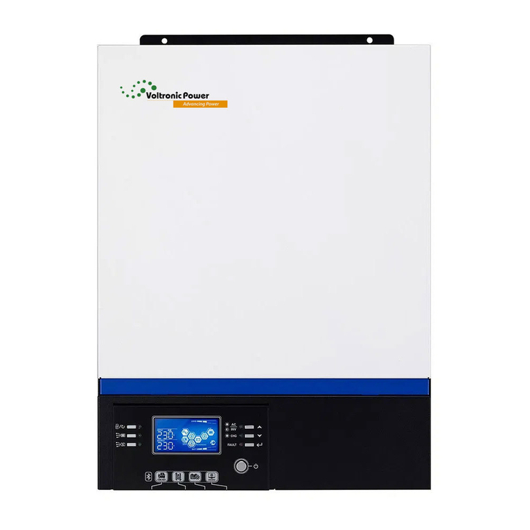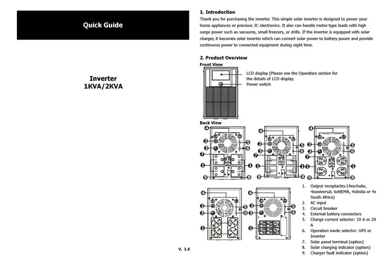
Axpert MKS-4000/KS-5000 Service manual
3
Table of contents
1. General information.......................................................................................................................................... 4
1.1 Getting start............................................................................................................................................ 4
1.2 Important safety instructions ............................................................................................................... 4
2. Functional block................................................................................................................................................ 6
3. Working principle of the major functional block............................................................................................ 7
3.1 Switch Power Supply............................................................................................................................ 7
3.2 DC TO DC dual converter (Full bridge converter)............................................................................ 8
3.3 Inverter (Full bridge)............................................................................................................................. 8
3.4 Buck converter....................................................................................................................................... 9
3.5 MPPT solar chager............................................................................................................................... 9
4. Functional explanations for each PCB......................................................................................................... 11
4.1 Main board........................................................................................................................................... 11
4.2 Cntl board............................................................................................................................................. 11
4.3 SCC board ........................................................................................................................................... 11
4.4 COMM board....................................................................................................................................... 12
4.5 LED board............................................................................................................................................ 12
4.6 MPPT board......................................................................................................................................... 12
5. Interface............................................................................................................................................................ 12
5.1 LED Indicator....................................................................................................................................... 12
5.2 LCD Display Icons .............................................................................................................................. 14
6. Troubleshooting............................................................................................................................................... 17
6.1 Fault Reference Code........................................................................................................................ 17
6.2 Warning Indicator................................................................................................................................ 18
6.3 Trouble shooting according to fault indication................................................................................ 18
6.4 Quick start............................................................................................................................................ 20
7. Test Step........................................................................................................................................................... 23
8. Electrical specification.................................................................................................................................... 24
Table 1 Line Mode Specifications .................................................................................................................. 24
Table 2 Invert Mode Specifications............................................................................................................... 25
Table 3 Charge Mode Specifications............................................................................................................. 26
Table 4 General Specifications....................................................................................................................... 26
Charging Controls............................................................................................................................................ 26
